Checking of models built using a graphically based formal
modelling language
Robert John Walters
*Declarative Systems and Software Engineering Group, School of Electronics and Computer Science, Room 3229, Level 3, Zepler Building, Highfield, University of Southampton, Southampton SO17 1BJ, UK
Received 15 December 2003; received in revised form 15 April 2004; accepted 15 June 2004 Available online 26 August 2004
Abstract
RDT is a graphical formal modelling language in which the modeller works by constructing diagrams of the processes in their model which they then join together to form complete systems. Aside from the benefits which accrue as a side effect of building a formal model of a proposed system, these diagrammatic models can be useful as a means of communication between the develop-ment team and the users. However one of the greatest benefits of a formal model is that it can be subjected to rigorous examination to ensure that it satisfies properties required of the system.
This paper describes the RDT language and a transformation from RDT into Promela code (the input language of the SPIN model-checker) which can be performed automatically and illustrates the use of the technique with an example.
2004 Elsevier Inc. All rights reserved.
Keywords:Formal modelling; Model checking; Graphical models
1. Introduction
As computer and other systems become larger and more complex we need to find methods which enable us to manage this complexity. A winning technique in other areas has been to break the problem into pieces and combine these into systems. In electronic hard-ware this approach has been spectacularly successful (Barjaktarovic et al., 1995; Beizer et al., 1997; Clarke et al., 1994; Gravell and Henderson, 1996; Grumberg and Long, 1994; Henderson and Walters, 1999; Holz-mann, 1997;Sullivan et al., 1997). The size of the pieces is a balance. Smaller pieces are easier to handle, but more difficult to assemble into a useful whole.
There are two issues which need to be addressed when a system is constructed from components: we need to connect the components, and then we have to get the
completed assembly to display the behaviour we require. The question of how to make pieces of software fit to-gether has been the subject of considerable effort in recent years. Systems and schemes such as COM, EJB, RMI and Message Queuing Middlewares exist which address these issues (IBM, 2001; Microsoft, 2001; Platt, 1999; Sun Microsystems;1Szyperski, 1998;Thomas, 1998). Typi-cally, these arrangements work by requiring components to conform to rules about how they interact with the oth-ers set by defining interfaces which they are required to respect and through which they interact with each other. Components are prevented from damaging each other (Henderson, 1998) and constrained to perform interac-tions which should be understood. We see this technique applied in the physical world with things like the standar-dised physical plugs and sockets we use for various appli-cations. The problem of behaviour is more subtle and
0164-1212/$ - see front matter 2004 Elsevier Inc. All rights reserved. doi:10.1016/j.jss.2004.06.023
* Tel.: +44 238059 3055; fax: +44 238059 3045. E-mail address:[email protected]
1Sun Microsystems, Enterprise Java Beans. Available from:http:// www.sun.com>
difficult. We need to ensure that the assembled system be-haves as required. Outside of software, this can be quite simple because the behaviour at the interface is simple.
Unfortunately, just being able to connect software components does not ensure that the resultant system will do what we want or expect. Software systems can be highly complex and have complex interactions with each other. They also live in a virtual world which is not subject to the sort of constraints with which we are familiar in the physical world. As a result, when we connect software components into a system, we not only have to master the familiar problems of all compo-nent systems of compocompo-nents, but we also have to ensure that the system does not have any emergent properties which are at variance with the behaviour we desire. These emergent properties are particularly troublesome as they are typically very hard to predict from examina-tion of the components of a system in isolaexamina-tion. This is where models can help. By executing a model of a pro-posed system, we can obtain answers to questions about the behaviour of systems before they have been built. However, to get these answers we need to build appro-priate models and then analyse them. This analysis could be as simple as reasoning based on a diagram but, to be really useful, it needs to be more thorough and for that we need models which have sufficient for-mality to permit analysis using techniques such as execu-tion or model checking.
The marked reluctance of potential users of these tech-niques to get to grips with traditional text based formal modelling languages inspired the creation of the RDT modelling language (Walters, 2002a,b). In RDT, the modeller works with a tool to draw diagrams of their pro-cesses and how they are combined into complete systems. Although the model is ultimately represented in code, the modeller/developer works with a model generation tool which draws diagrams of the model and the modeller is never required to read or write the code. To assist in the generation of their models, the RDT toolset includes an execution tool. With this tool, the modeller can per-form test executions of their model. However, if the mod-eller is to make confident assertions about the behaviour of a model, the analysis needs to be more rigorous. This analysis could have been provided by building model checking into the toolset, but RDT uses an alternative ap-proach. In addition to providing the model generation tool and the execution tool, the RDT toolset includes a translation tool which will perform an automatic transla-tion of an RDT model into the input language of the lead-ing model checker, SPIN (Holzmann, 1997).
2. The RDT language
RDT (Walters, 2002a,b) is a graphically based formal modelling language. It is a small language which does
not attempt to emulate the expressive power of more traditional modelling systems. Instead it provides a min-imal collection of features with communication between processes inspired by the pi-calculus (Milner, 1989, 1993). The communication between processes in RDT is channel based and point to point. When a process sends a communication, it writes a value into a channel. There may be any number of processes which know of the channel and are prepared to read a value from a channel but only one of them will actually be able to read the value from the channel. In contrast with com-munications in the pi-calculus, which is synchronous, RDT offers the modeller the option to specify the length of channels in their model. If the modeller elects to have zero length channels, then the communication is syn-chronous and follows the pi-calculus very closely. If the channel length is non-zero, the channels acquire the behaviour of buffers and the synchronization be-tween the sending of a message and its removal from the channel by the receiving process is broken. Argu-ably, this feature is unnecessary as the modeller can achieve the same behaviour by building buffers into their model. However, it was felt that it should be included for two pragmatic reasons: First, it permits the modeller to adapt the communication style in their model to match that which will be used in the implementation thus simplifying the mapping from the model to the implementation. Secondly, it was felt that requiring the modeller wishing to use asynchronous communica-tions to build and insert their own buffers is likely to be considered to be onerous by the target audience as well as potentially error prone. In common with the pi-calculus, there is just one data type which is passed between processes which, in RDT, is generally referred to as a channel although where the context permits, these values are also used to represent other data as re-quired. The ability of RDT processes to (create and) pass channel type values along channels gives RDT the power to build models of systems in which the inter-connections between processes can be reconfigured dur-ing execution.
The intention was to build a language which is small enough for a new user to assimilate its essential concepts in a few hours without imposing severe restrictions on the systems which could be modelled. A complete model in RDT comprises of a collection of processes which are connected and communicate using channels.
which is shown as a branch in the line of control. How-ever, unlike a RAD, an RDT process does not have the option of performing actions in parallel so there is no need for the use of any decoration to branches in the line of control since choice is the only reason for this to occur. Where more than one event have the same after-state, the lines are joined appropriately in the same manner as in a RAD. All processes start in a distin-guished state called ‘‘Initial’’.
In addition to the internal change of named state in the process, each is associated with a communication. There are three types, Read, Write and Create. A Write is shown as a clear square and causes a named value to be placed into a channel. A Create event is a special case of a Write event distinguished in the diagram by a cross in its box. When a Create event occurs, a new channel (value) is first created and associated with the local name used by the process for the value being sent. This new value is then sent on the channel. The final type of event is Read which is complementary with the Write and Cre-ate events. It is distinguished by being drawn as a black square. It takes a value from a channel which is then associated with the local name specified in the event.
Events may only occur if the process is in the required preceding state and the communication associated with them may occur. So, for a Read event, there must be a value available on the named channel for the process to read. In the case of a model in which the channels are buffered, this corresponds to there being a value in the channel waiting to be read. In the case of zero length channels, there must be another process which will simultaneously place a value into the channel. With a Create event, the channel into which the value is to be written must be capable of accepting the value, either because the channel is buffered and not full or, in the case of a zero length channel, there exists another pro-cess which is waiting to read a value from the channel. The same condition applies to a Write event with the additional constraint that the local name given to the value to be written must be associated with a suitable value. This final constraint is always satisfied for a Cre-ate event since a new value is generCre-ated and associCre-ated with the local name for the value sent as a side-effect of the event itself.
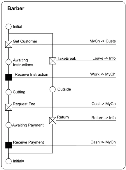
Fig. 1shows an example of a process description in RDT. To generate a process description, the modeller describes the events in which the process takes part to the RDT model generation tool by means of a series of dialogue boxes which guide the modeller through the activity. Wherever possible, the tool offers the mod-eller a choice of options from which to make a selection. This affords the benefit of making the models easier for the inexperienced modeller to construct whilst at the same time helping to eliminate the class of problems which occur when the modeller is inadvertently inconsis-tent in their use of identifiers in their work. The diagram
is generated and displayed entirely automatically from the information about the events supplied by the model-ler and the diagram is reconstructed each time an event is added or altered.
The process shown describes a behaviour for a Bar-ber in a traditional gentlemanÕs barbershop. The process starts in the distinguished state of Initial. From here, it has a choice of two actions. It may send a new value (which it refers to locally by the name, ‘‘MyCh’’) onto the channel it knows as ‘‘Custs’’. In doing so, the pro-cess moves to a state named, ‘‘Awaiting Instructions’’. From this state, the Barber receives instructions (from its customer) along the new channel ‘‘MyCh’’ and moves to the named state ‘‘Cutting’’. This is followed by a fur-ther pair of interactions concerned with obtaining pay-ment. The Barber is then returned to its initial state and is ready to start again. As in a RAD, an RDT pro-cess description permits states which are re-visited to be re-drawn lower in the diagram. The modeller can give the diagram drawing algorithm of the model generation tool a hint that a state should be redrawn lower in the diagram by adding a suffix of one of more ‘‘=’’ to the state name. These are stripped off automatically when the model is used outside of the generation tool. From the initial state, the process may alternatively fol-low the other path along which it places a notification onto the channel it knows as ‘‘Info’’ that the Barber is taking a break. This is followed by a further event which
Barber
Get Customer MyCh -> Custs Initial
Request Fee
Work <- MyCh
Cost -> MyCh Receive Instruction
Initial= Awaiting Payment
Receive Payment Cash <- MyCh Leave -> Info
Return -> Info TakeBreak
Return Outside Awaiting
Instructions
[image:3.595.316.532.68.360.2]Cutting
places a similar notification onto the ‘‘Info’’ channel when the BarberÕs break is complete and the Barber again returns to the initial state.
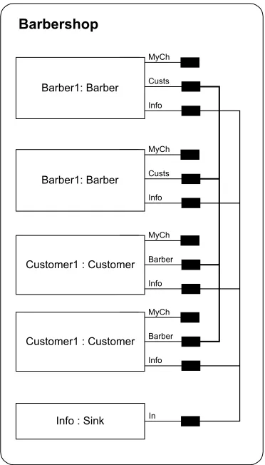
The second part of the description of an RDT system is the ‘‘model’’ diagram in which the modeller specifies a collection of processes and how the channel names they use are connected, if at all. As with the pi-calculus, the values passed along channels may be used as channels so that the initial connections between processes speci-fied in this diagram may be supplemented and changed during execution. Fig. 2shows an example of this type of diagram showing a model in which two instances of the Barber process (named Barber1 and Barber2), two instances of a Customer process (named Customer1 and Customer2) and one of a Sink process (named Info) are connected to form a complete model. Each process instance is drawn as a box in which the instanceÕs name and type is written. Along the right hand side of each process instanceÕs box, each of the channels along which any of its events sends or receives a value is shown by a small black rectangle joined to the box. Associations or connections between these are shown by lines connect-ing them. In this particular example, the channels known to Barber1 and Barber2 as ‘‘Info’’ are shown as being connected with the channel known to the Info
process as ‘‘In’’. The meaning of this connection is that, when the model is executed, these three names known locally within the process instances as ‘‘Info’’, ‘‘Info’’ and ‘‘In’’ in the two Barbers and the Sink all refer to the same channel, thus permitting the intended commu-nication to occur.Fig. 2shows a further connection be-tween the channels known with in the Barbers as ‘‘Custs’’ and the Customers as ‘‘Barber’’. Notice that, none of the channels known within the processes as ‘‘MyCh’’ is connected in the diagram. This is not an error. These channel names become associated with channels during execution of the model as consequences of the Create and Read events which occur.
To draw this diagram, the modeller uses the model generation tool to specify the names and types of the process instances they require. They then make the re-quired connections between them. As with the process diagram, this diagram is generated automatically by the tool and reconstructed each time a change is made. It should be noted that RDT makes a sharp distinc-tion between these two diagrams and the nature of the entities which they describe. The process diagram de-scribes the way a sort of process behaves in general––a type of behaviour. The ‘‘model’’ diagram deals with the assembly of a collection of instances of these pro-cesses and the interconnections between them.
In addition to the model generator, the RDT tools provide an animation tool in which a modeller may exe-cute their model by hand (and the translation tool which performs the automated conversion into Promela). Using the animation tool, the modeller can perform a step by step execution of their model. Execution in this way can help the modeller to build confidence in the cor-rectness of their model as well as identifying and under-standing problems. However, although there is no reason why it should not be possible, modellers rarely find all of the possible problems in a model using this technique alone. The reason is not altogether clear but it seems likely that there are several elements which in-clude the modeller failing to explore some possible branches of execution by repeating the same or similar choices even when they are trying to make random selec-tions and subconsciously applying their knowledge of how the model is intended to operate. If a model is to be thoroughly analysed, something more rigorous is re-quired and this is where model checking can help.
An obvious route to providing this kind of analysis of an RDT model would have been to build a model check-ing tool to complement the model generation and execu-tion tools. However, highly featured and respected model checkers already exist so it was felt appropriate to adopt the alternative approach of providing a tool which would perform an automated translation of an RDT model into a form suitable for input to an existing model checker. By following this route to checking their RDT model, the modeller is able to enjoy performance
Barber1: Barber
MyCh
Custs
Info
Customer1 : Customer MyCh
Barber
Info
In Info : Sink
Barber1: Barber
MyCh
Custs
Info
Customer1 : Customer MyCh
Barber
Info
[image:4.595.77.263.393.719.2]Barbershop
and features in their model checking which far exceed those which could be provided in a tool dedicated to RDT.
3. Selecting a target model checker
If we are to model check our models using an exist-ing tool, we first need to select a suitable target model checking tool. The models described by RDT in its dia-grams are finite state machines, so in principle, it would be possible to use any of the many model checking tools available to analyse its models. However, two tools stand out as potential candidates, FDR (FDR2 User Manual, 2000) and SPIN (Holzmann, 1997). Both are mature, well established and respected systems, with attractive window based user interfaces, though they differ significantly in their input language and the way that the property to be verified is specified to the system.
FDR uses a variant of CSP (Hoare, 1985) as its input language. The language is powerful and fully featured though for our target audience it has the disadvantage that it would not look familiar to a programmer. Its communication is synchronous along typed channels. By contrast, SPIN uses its own input language which has a syntax reminiscent of, but not the same as, the ‘‘C’’ programming language (Kernighan and Ritchie, 1988). Communication in SPIN is also by typed chan-nels, but permits the modeller to specify their length. After consideration, the SPIN model checker was se-lected for the following reasons:
• At some point the modeller may need to relate the code generated for the model checker to their model. It is felt that our target users are likely to be familiar with programming languages and so will feel more comfortable with the Promela code of SPIN with its superficial similarity to the ‘‘C’’ programming guage than the process algebra inspired input lan-guage of FDR.
• Although the actual code required is potentially diffi-cult to construct, it was felt that the notion of giving the property to be checked to SPIN directly is likely to feel more natural to our target audience then the ‘‘refinement’’ based notion used by FDR.
• Promela channels have a more natural correspon-dence with the channels of RDT. In particular, the modeller is able to specify the length of channels in Promela, including length zero which enforces syn-chronous communications. It is also possible in Pro-mela to define a channel along which values of type ‘‘channel’’ may be passed.
A final advantage of the SPIN model checker is that it is available free of charge for use on several platforms,
including Windows, the platform on which the RDT tools run. This permits the curious potential user to experiment with this the tool without first making a financial commitment.
4. Translating from RDT to Promela in outline
Promela is a rich, expressive language in which to specify models for analysis with SPIN. A model in Pro-mela may be constructed in a number of ways but the following outline is typical. The modeller starts by defin-ing the behaviour of the component processes which will be composed to form their complete model by defining a ‘‘proctype’’ for each of them. The notion of ‘‘proctype’’ in Promela is similar to that of a process in RDT. The modeller then constructs their completed model from these components and a ‘‘proctype’’ called ‘‘init’’. ‘‘Init’’ is a distinguished ‘‘proctype’’ name in Promela which has the property that, when SPIN loads a model in which such a process has been defined, SPIN creates a single instance of the process and sets it running. There are other mechanisms available to the modeller in Pro-mela to initialise their model. There will be many possi-ble representations of RDT models in the language. This paper describes the one which is performed automati-cally by the RDT tools.
The conversion of an RDT model is made in two parts: First, each of the processes is transformed into a Promela process (‘‘proctype’’) and then a collection of instances of these is assembled into the completed sys-tem as specified in the ‘‘model’’ diagram of the RDT model in an ‘‘init’’ process.
4.1. Processes
During execution of a model by RDX, the RDT exe-cution tool, as each event occurs each of the processes in the model reconstructs its list of available events. Whether an event is available depends on the present state of the process (instance) concerned and the willing-ness of the channel the event interacts with to accept the write or read associated with the event. This suggests a structure for a Promela description of one of our pro-cesses as a Promela process with a variable to record its state and a single ’’do’’ loop with each branch repre-senting one of its events. Each branch of the loop would be guarded by a conditional statement dependent on the current value of the ‘‘state variable’’ of the process and the availability of the required communication. How-ever, this scheme is unsatisfactory for two reasons in particular:
is exercised since if the process was able to perform even a single event, SPIN would report it as one which had been thoroughly exercised.
• Promela does not have a string type, so the state of the process would have to encoded into a numeric form which would make interpretation difficult for the human reader. (Promela does have ‘‘symbolic constants’’ which could be used, but just one declara-tion of this type is permitted in each file, so if it were used, all of the states of all of the processes would have to be declared in a single collection.)
The solution adopted is to use labels and explicit ‘‘goto’’ statements which are permitted in Promela. Each of the labels in the code for a process description corresponds to the named state of the RDT process it represents. Using the process state names for these labels eases the task of relating the automatically generated code to the diagram of the process in RDT.
Each of the labels in the process corresponds with one of the named states of the RDT process and is normally followed by an ‘‘if’’ statement. Within this statement, there is a branch for each of the possible events which can follow this named state in the RDT process dia-gram. Each branch starts with an expression which per-forms the communication associated with the appropriate event followed by a ‘‘goto’’ statement tak-ing execution to the labelled point in the description cor-responding to the ‘‘after’’ state of the chosen event, the new named state of the process. In the case of a state which is not the before-state of any event, the process is unable to proceed further and the ‘‘if’’ statement is re-placed with ‘‘skip’’ (which is a statement which does nothing but is required to satisfy the syntax of Promela which requires that a label must prefix a statement).
Figs. 3and 4show two elemental processes in RDT. The process in Fig. 3 Sends a value (the name of the channel it is writing to) on a channel it knows as ‘‘Out’’. In doing so, it moves from its first state (named Initial) to a new state named Done which it is unable to
leave. The first part of Fig. 5shows how this process is translated into Promela code. A proctype named ‘‘Source’’ is declared. The definition of this proctype starts with the label Initial. This is followed by a Pro-mela ‘‘if’’ statement. Each possible exit from the state-ment starts with a double colon (::). This is followed by a series of statements which are executed if that branch is taken. Only those branches where the first statement in the series can be executed are available so the statement acts as a guard on the selection of a branch. Here there is just one branch corresponding with the action named, ‘‘Send’’. The first statement in the branch actions the communication associated with the event and is followed by a goto statement which moves the point of execution to the label ‘‘Done’’ which corresponds to the change of state of the process.
Upon entering the state named, ‘‘Done’’, the RDT process is unable to perform any further actions so it would be natural for the code associated with this label to be empty. However, to satisfy the syntax of Promela a
Send
Out -> Out Initial
[image:6.595.360.505.71.226.2]Done Source
Fig. 3. A ‘‘Source’’ process in RDT.
Read
Val <- In Initial
Initial= Sink
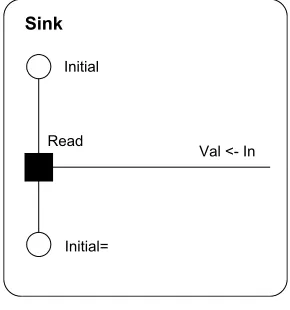
Fig. 4. A ‘‘Sink’’ process in RDT.
[image:6.595.98.240.570.720.2]‘‘skip’’ statement is used. As mentioned previously, this is a statement in Promela which has no effect when executed.
This completes the code defining the Promela proc-type for the Source process described in RDT.
Fig. 4shows a complementary process which reads a value on the channel it knows as ‘‘In’’ which it stores (and is later able to refer to) as ‘‘Val’’. This process then returns to the Initial state and is ready to repeat the event. This second process is translated into the code in the second part ofFig. 5.
All of the channels which these processes use are de-fined elsewhere and supplied to them as parameters. The reason for this will become clear in the next section.
4.2. Models
With the transformation of the process descriptions into Promela proctypes complete, code is required to assemble instances of these into the complete system specified in the RDT ‘‘model’’ diagram. The technique adopted is to construct the system required in an ‘‘init’’ process.
The objective of the code in the ‘‘init’’ process is to create the particular collection of process instances spec-ified in an RDT model, together with the interconnec-tions between them. Clearly, where the RDT model has a number of process instances, the ‘‘init’’ process can reproduce this by starting instances of the appropri-ate proctypes. The connections of the RDT model are created by giving the same channel name as a parameter to two (or more) processes. Thus enabling them to com-municate by writing values into and reading values from that channel.
In Promela channels need to be declared (like vari-ables in many programming languages). There are a number of issues which need to be decided about the channels, including their type, length and where they should be declared. Their declarations may be global, within a process or (declared elsewhere and) passed to the process as a parameter. The matter of the type of the channels is decided by the ability in RDT for pro-cesses to use values sent along channels as channels. The consequence of this is that the channels in the Pro-mela version of the model must be able to carry a value which the receiving process may use as a channel. This means that the only type these channels can be is chan-nels which carry values of type channel. The matter of how long the channels should be is also readily resolved. RDT permits channels to be any (fixed) length, includ-ing zero but this is not explicitly stated in the diagrams. The RDT execution tool permits the modeller to enter the length of channel they wish to use at runtime. A sim-ilar technique is employed in the translation of the model into Promela. The length of channels is elicited from the modeller before translation begins. In order
to permit the modeller to experiment with differing channel configurations without repeating the translation every time, the selected channel length is inserted into the Promela code in the header as a constant which is re-used each time a channel is declared. This constant is declared in the style familiar to ‘‘C’’ programmers. The example code inFig. 7shows this constant declared to be 4 in the first line.
The issue of where channels are declared is less clear cut. An obvious option would be for those channels which a process knows and which are associated with channels in other processes at the start of execution (those involved in the connections of the RDT model diagram), to be supplied to processes as parameters. The remainder could then be declared locally within the process which uses them. However, this brings with it one particular disadvantage. If, in a single RDT model, different instances of a particular type of process had a different subset of channels connected, this would imply that different instances would require different parameters. Hence a separate proctype would be needed for each different arrangement of connections. Aside from the complexity this would add to the trans-formation process, it would also disrupt the simple association between an RDT process and its proctype in the Promela code. The alternative adopted is to sup-ply all channels used within a proctype as parameters, whether or not they are the subjects of a connection at the start of execution. This permits the definition of any RDT process as a single proctype in Promela regardless of the arrangement of connections that might need to be made to it at the start of execution. A dum-my value is supplied for those parameters to a process which are not the subject of connections. Each of these values needs to be declared separately to ensure that there can be no possibility of any communications occurring between processes using these place-holding channels.
The process for transforming an RDT model into Promela code is summarised as follows:
1. Channels of the required length are declared for each of the required connections between the process instances.
2. Placeholder channels are declared to be supplied to process instances as placeholders for any channel names they know, but are unconnected initially. 3. An ‘‘init’’ process is created which uses a sequence of
‘‘run’’ statements to bring the required process instances into existence and set them running.
are in place before any part of the system starts to operate.
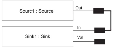
Fig. 7shows the code generated from the RDT model shown inFig. 6. Notice also that a channel (ch0) is cre-ated and passed to both processes to make the connec-tion shown in the diagram and that, since the channel known to the process ‘‘Sink1’’ as ‘‘Val’’ is initially unconnected, a placeholder channel (nch0) is declared and passed to the process. The length of place-holder channels is unimportant since they can never be used for communication.
4.3. Channels and values
Communication in RDT is inspired by the pi-calcu-lus (Milner, 1993) in which there is just one type of value, referred to as a ‘‘name’’. RDT takes the same view: values passed in communications are all of the same type. In some contexts, a value passed between processes may represent a value such as the result of a computation. In others the value passed may be a channel which may be used for later communications. It is this ability to pass channel typed values along channels which permits the dynamic re-configuration of RDT models.
In contrast with the pi-calculus and RDT, Promela channels are typed according to the kind of values they carry. One of the permitted types of value that a Pro-mela channel is permitted to carry is a channel and, since potentially an RDT process may use any value it knows as a channel, it is this type of channel which is
used throughout the Promela code generated from an RDT model.
5. Issues
Two issues remain which have not been addressed in the transformation described so far. The first concerns a difference between the acceptable use of the ‘‘Read’’ event in RDT and the action of reading from a channel in Promela. The second concerns the ‘‘Create’’ event in RDT. This event type is useful as it permits processes to create the new channels needed to create new connec-tions between processes at runtime, although they may also be used just as simple values.
5.1. A special case of a Read event in RDT
RDT permits a process to read a value on a channel and assign the name received to the name used as shown in Fig. 8.
According to our scheme, this would cause the fol-lowing code to be generated:
if ::X?X;
goto second; fi;
Unfortunately, ‘‘X?X’’ causes SPIN to generate an er-ror, so the following alternative code is used where necessary:
chan tmp;
if
::atomic{X?tmp; X = tmp;}
goto second; fi;
Fig. 7. The ‘‘init’’ process.
Out
In
Sourc1 : Source
[image:8.595.74.266.69.149.2]Sink1 : Sink Val
Fig. 6. A model showing a Source process with its ‘‘Out’’ channel connected to the ‘‘In’’ channel of a Sink process.
Proc 1
AnEvent
X <- X Initial
[image:8.595.366.498.559.708.2]Second
5.2. The RDT ‘‘Create’’ type event
The problem deriving code for the behaviour of the ‘‘RDT’’ Create event is not so easily addressed. An in-terim workaround has been implemented in the transla-tion tool. This provides any process which contains a create-type event with a supply of channels. The process then allocates a channel from this supply whenever it needs a fresh value for a Create event. When the supply is exhausted, the process will be unable to carry out an-other Create event. Unlike the an-other channels, this sup-ply of channels is declared as part of the description of each process. So long as the number of channels in this supply is sufficiently large in the context of the model, this solution does not impact on the behaviour of the model. The size of this cache of channels is elicited from the modeller at the same time as the channel length. It is then defined at the head of the file in the same manner as the channel length.
A complete solution to this problem which is not yet implemented would be based on the following observa-tion: In an RDT model, each process knows some num-ber of channels which it refers to using its own collection of local names. The assignment of these channels to names changes at runtime when a process reads a chan-nel or uses ‘‘Create’’ to generate a new chanchan-nel––and if the name to which the new value is assigned already re-fers to a channel, the existing value is overwritten. A consequence of overwriting channel names is that, un-less the process has taken explicit steps to prevent it, knowledge of the overwritten channel is lost at the same time. Processes in RDT are unable to locate channels by any method other than being told of them by other pro-cesses and creating new ones. Consequently, should a channel ever reach a condition where none of the execut-ing process instances has it associated with any of their names, the channel is irretrievably lost to the model and the system could safely destroy that channel together with any values stored in it.
Since, for a channel to be used by a process instance, it must ‘‘know’’ the channel by having it associated with one of its channel names, no running RDT model can possibly have more channels in use than there are local names for them in all of the process instances of the model. Consequently, the translation tool could gener-ate code which, by the reclaiming of channels which are no longer visible to any of the process instances could guarantee to always have a channel available to allocate to a process which sought to perform a ‘‘Cre-ate’’ event. A complete implementation of this scheme would need to note and remove any values found in recovered channels as their presence may be an indica-tion of a fault in the model and being able to see the val-ues which are left in lost channels may be of assistance to the modeller when analysing and correcting the model.
6. Conclusion
The RDT modelling language together with its model generation and execution tools demonstrates that it is possible to construct useful formal models using a graphical idiom in place of the usual text based input. However, to make the best use of these models, their behaviour needs to be much more rigorously examined than the modeller can hope to achieve by hand even with the assistance of an execution tool. This might have been achieved by the construction of a model checking tool to supplement the existing RDT tools. However, model checking software is already available which is known to be accurate, powerful and efficient so it was felt that it would be preferable to provide a translation which could transform an RDT model into a form suitable for input into an existing model checker.
The model checking software chosen was SPIN with its programming-like input language, Promela. The motivation in the development of RDT is to make for-mal modelling as easy as possible for the inexperienced user so, the translation of an RDT model into Promela code had to be performed automatically. We cannot ex-pect the user to apply the transformation manually. At the same time, the transformation has to be into Pro-mela code which is sufficiently readable for the modeller to be able to identify its relationship to the original fea-tures of the RDT model.
The transformation described above can be per-formed mechanically and has been implemented in a tool which is able to take a model built using the RDT model generation tool and transform it into cor-rect Promela code automatically. Using this code, the modeller is able use SPIN to perform ‘‘standard’’ analy-sis (e.g., unreachable code and deadlock detection) of their model without learning the syntax of Promela and with an absolute minimum of knowledge of SPIN itself.
References
Barjaktarovic, M., Chin, S.-K., Jabbour, K., 1995. Formal specifica-tion and verificaspecifica-tion of communicaspecifica-tion protocols using automated tools. In: First IEEE International Conference on Engineering of Complex Systems (ICECCSÕ95), Fort Lauderdale, FL, USA. IEEE Computer Society Press, Silver Spring, MD.
Beizer, B., Juristo, N., Pfleeger, S.L., 1997. Cleanroom process model: a critical examination. IEEE Software, 114–118.
Clarke, E.M., Grumberg, O., Long, D.E., 1994. Model checking and abstraction. ACM Transactions on Programming Languages and Systems 16 (5), 1512–1542.
FDR2 User Manual, 2000. Formal Systems (Europe) Limited. Available from: http://www.fsel.com/documentation/fdr2/html/ index.html>.
Grumberg, O., Long, D., 1994. Model checking and modular verification. ACM Transactions on Programming Languages and Systems 16 (May), 843–871.
Henderson, P., 1998. Laws for dynamic systems. In: International Conference on Software Re-Use (ICSR 98), Vic., Canada. IEEE Computer Society Press, Silver Spring, MD.
Henderson, P., Walters, R.J., 1999. System design validation using formal methods. In: Tenth IEEE International Workshop on Rapid System Prototyping (RSP99), Clearwater, FL. IEEE Com-puter Society Press, Silver Spring, MD.
Hoare, C.A.R., 1985. Communicating sequential processes. Prentice-Hall International, Englewood Cliffs.
Holzmann, G.J., 1997. The Model Checker SPIN. IEEE Transactions on Software Engineering 23(5), 279–295.
IBM, 2001. MQSeries Family. Available from:http://www-4.ibm.com/ software/ts/mqseries/>.
Kernighan, B.W., Ritchie, D.M., 1988. The C Programming Lan-guage. Prentice-Hall, Englewood Cliffs.
Microsoft, 2001. Microsoft Message Queuing Services, Microsoft. Availabe from: http://www.microsoft.com/ntserver/appservice/ techdetails/overview/msmqrevguide.asp>.
Milner, R., 1989. Communication and Concurrency. Prentice-Hall, Englewood Cliffs.
Milner, R., 1993. The polyadic pi-calculus: a tutorial. In: Milner, R. (Ed.), Logic and Algebra of Specification. Springer-Verlag, New York.
Ould, M.A., 1995. Business Processes—Modelling and Analysis for Re-engineering and Improvement. John Wiley, New York. Platt, D.S., 1999. Understanding COM+. Microsoft Press.
Sullivan, K., Socha, J., Marchukov, M., 1997. Using formal methods to reason about architectural standards. In: 19th International Conference on Software Engineering, Boston. IEEE Computer Press, Silver Spring, MD.
Szyperski, C., 1998. Component Software. Longman, New York. Thomas, A., 1998. Enterprise JavaBeans Technology, Patricia Seybold
Group.
Walters, R.J., 2002a. A graphically based language for constructing, executing and analysing models of software systems. In: 26th Annual International Computer Software and Applications Con-ference (COMPSAC 2002), Oxford. IEEE Computer Society Press, Silver Spring, MD.
Walters, R.J., 2002b. A graphically based language for constructing, executing and analysing models of software systems. Ph.D. Thesis, University of Southampton.