ePrints Soton
Copyright © and Moral Rights for this thesis are retained by the author and/or other
copyright owners. A copy can be downloaded for personal non-commercial
research or study, without prior permission or charge. This thesis cannot be
reproduced or quoted extensively from without first obtaining permission in writing
from the copyright holder/s. The content must not be changed in any way or sold
commercially in any format or medium without the formal permission of the
copyright holders.
When referring to this work, full bibliographic details including the author, title,
awarding institution and date of the thesis must be given e.g.
AUTHOR (year of submission) "Full thesis title", University of Southampton, name
of the University School or Department, PhD Thesis, pagination
UNIVERSITY OF SOUTHAMPTON
FACULTY OF ENGINEERING, SCIENCE & MATHEMATICS
School of Engineering Sciences
Three dimensional geometrical and material
nonlinear finite element analysis of
adhesively bonded joints for marine structures
by
Narasimhan Sampathkumar
Thesis for the degree of Doctor of Philosophy
I sincerely express my gratitude to Professor Ajit Shenoi who offered me this research
work and for his invaluable guidance as my supervisor. It was a great privilege to work
with him and his continued support throughout the work period and particularly at
crit-ical stages of my research are highly regarded.
I also express my thanks to Prof. W.G. Price, the head of Fluid Structure Interactions
Research Group and to Prof. P.A. Wilson for providing the computational facilities and
their kind support throughout the research programme. Special thanks to Dr. James
Blake, Dr. A.K.Nayak and my colleagues E. Jarry and S.W. Boyd for the useful
discus-sions I had at times. Also my thanks are to Dr. Ming-Yi Tan for his technical support
and to all other colleagues in Fluid Structure Interactions Research Group.
This work would not have been possible without the support from my Parents,
Broth-ers and from my sister Pavithra. Their care towards my wellbeing, their patience and
forbearance are acknowledged gratefully. I am extremely thankful to my friends Neeraj,
Vinu, Arindam, Darun, Krishnan and many other friends in the university campus for
their encouragement and for providing homely comfort.
The use of adhesive bonding as a structural joining method has been gaining recognition in
marine industry in recent years, though it has been widely adopted in other fields such as
aerospace, automobiles, trains and in civil constructions. The type of materials used and
design practices followed in marine structures are different from what is applied in other
disciplines. Therefore new research approaches are required and recent novel ideas are
ex-plored in the context of application of bonded joint configurations in marine environment.
The research is directed at developing analysis tools for predicting the displacement,
stress and strain fields in adhesively bonded joints between dissimilar adherends. In the
finite element formulation, the adherends may be isotropic or orthotropic layered
materi-als, which are assumed to behave linear elastically. The adhesive material is assumed to
behave as elasto-plastic continuum, where the nonlinear behaviour is modelled as either a
rigid or a semi-rigid adhesive solid that can be represented by the Ramberg-Osgood
ma-terial model. The yield behaviour of the polymeric adhesive is modelled using a modified
von Mises criterion, which accounts for the fact that plastic yielding of polymer materials
may occur under the action of hydrostatic as well as deviatoric stresses. The geometric
nonlinearity is based on the assumption of large displacement, large rotation but small
strain, and it is implemented in the code using the total Lagrangian approach.
The scheme is applied on three case studies viz.: a study of adherend imbalances in
a single lap joint, stress analysis of a butt-strap joint system and a hybrid joint are
un-dertaken. The influence of geometric and material nonlinearity on joint deformations and
adhesive stresses, are studied for a single lap joint with dissimilar adherends, aluminium
and a Fibre Reinforced plastic composite material, with varying adhrend thickness ratios.
The adhesive stress-strain data obtained from the model are compared with the
exper-imental stress-strain curve and the numerical results are validated with the analytical
solution. Three dimensional effects like ’anticlastic’ and bending-twisting’ are shown in
the joint with a dissimilar adherends. Key results are obtained that explains the state of
nonlinear adhesive stress state in the joint.
Analysis of butt-strap joint focussed on nonlinear modelling of a semi-rigid adhesive
ma-terial that is used to bond two dissimilar adherends, steel and aluminium. The analysis
demonstrate that the influence of geometric and material nonlinearity on the joint
de-formations as well as the adhesive stresses is significant. Nonlinear adhesive stresses are
compared with the actual strength of the highly flexible adhesive, highlighting the need for
the consideration of material nonlinearity in the bonded joints. Failure modes for the joint
are inferred from the observations made on the adhesive stress state in the butt-strap joint.
Last study, deals with three dimensional analysis of a GRP-Steel hybrid joint carried
out to model the initiation and propagation of crack under a set of static loading cases.
Earlier studies were restricted only to two dimensional analysis. This three dimensional
analysis showed that the adhesive normal stress is not constant across the width of the
joint. Critical locations of stress concentrations are identified and the failure mechanisms
are compared with the experimental specimens.
The observations made from this research study using a three dimensional finite element
List of Publications produced from this thesis
1. Narasimhan S., Shenoi R.A. and Jeong H.K. (2004) Three-dimensional stresses in
adhesively bonded lap joints with non-identical adherends, IMechE proceedings, Part-L:
Journal of Materials: Design and Applications, Vol.218, No.L4, pp. 283-298.
2. Narasimhan S. and Shenoi R.A. (2005) Analysis of bonded butt-strap joints for marine
structural applications,Marine Structures, Review in Progress.
3. Narasimhan S., Shenoi R.A., Blake J.I.R. and Boyd S.W. (2005) Stress
concentra-tions in three dimensional hybrid composite-steel joint model, Proceedings of Fifth Intl.
Conference on Composite Science and Technology (ICCST/5), American University of
Sharjah, Sharjah-UAE, pp. 143-148.
4. Narasimhan S. and Shenoi R.A. (2005) Numerical modelling of hybrid GRP-Steel
joint subjected to in-plane and out-of-plane loadings, Communicated toComposites-Part
Acknowledgements i
Abstract ii
List of Figures ix
List of Tables xiii
Nomenclature xiv
1 Introduction 1
1.1 Adhesively Bonded Joints . . . 2
1.1.1 Function and Failure of Adhesively Bonded Joints . . . 2
1.1.2 Advantages and disadvantages of adhesive connections . . . 3
1.2 Sources of Nonlinearity . . . 5
1.2.1 Geometric Nonlinearity . . . 5
1.2.2 Material nonlinearity . . . 6
1.3 Selection of structural adhesives . . . 7
1.4 Aim and Scope of the Research . . . 8
1.4.1 Motivation . . . 8
1.5 Areas of investigation . . . 10
1.6 Layout of thesis . . . 11
2 Critical Literature Review 18 2.1 Introduction . . . 18
2.2 Lap joint theories . . . 18
2.2.1 Review . . . 18
2.2.2 Discussion . . . 23
2.3 Modelling of Adhesives . . . 25
2.3.1 Review . . . 25
2.3.2 Discussion . . . 28
2.4 Experimental modelling of adhesive joints . . . 32
2.4.1 Review . . . 32
2.4.2 Discussion . . . 36
2.5 Numerical modelling of adhesive joints . . . 37
2.5.1 Review . . . 37
2.5.2 Discussion . . . 46
2.6 Summary . . . 50
3 Proposed Methodology 54 3.1 Introduction . . . 54
3.2 Study of lap joint with non-identical adherends . . . 54
3.2.1 Study of a butt-strap joint system . . . 56
3.2.2 Study of GRP-Steel hybrid joint . . . 58
3.3 Proposed Methodology . . . 60
4 Solution Procedures and FE formulation 63 4.1 Introduction . . . 63
4.2 Geometric nonlinear aspects . . . 63
4.2.1 Definitions of strains and stresses . . . 64
4.2.2 Explicit form of Lagrangian formulation . . . 67
4.2.3 Isoparametric finite element formulation . . . 75
4.3 Material nonlinear formulation for adhesive material . . . 78
4.4 Elasto-plastic analysis of solids . . . 79
4.5 Finite element formulation of Quasi-static elasto-plastic problems . . . 82
4.5.1 Vector form of the elasto-plastic constitutive relations . . . 82
4.5.2 Modified von Mises yield criterion . . . 84
4.5.3 Time discretization of elasto-plastic equations . . . 85
4.5.4 Stress-Strain Constitutive Relations . . . 87
4.6 Incremental equations of equilibrium . . . 88
4.7 Convergence criteria . . . 91
4.7.1 Force criteria . . . 92
4.7.2 Displacement criteria . . . 92
4.8 Computational Procedure . . . 93
4.9 Conclusions . . . 95
5 Study on adherend imbalances in single lap joint 98 5.1 Introduction . . . 98
5.2 Problem definition . . . 99
5.3 Material nonlinearity in the adhesive material . . . 100
5.3.1 Characterisation of the adhesive material . . . 101
5.3.2 Yield criterion for the rigid adhesive material . . . 101
5.4 Results and Discussions . . . 102
5.4.1 Generation of FE mesh . . . 102
5.4.2 Validation of FE results . . . 103
5.4.3 Nonlinear deformations . . . 104
5.4.4 Nonlinear stresses . . . 105
5.5 Critical assessment of results . . . 108
6 Analysis of Butt-strap joint structures 127
6.1 Introduction . . . 127
6.2 Problem definition . . . 127
6.3 Implementation of material nonlinearity . . . 129
6.3.1 Characterisation of the adhesive material . . . 129
6.3.2 Yield criterion for the semi-rigid adhesive material . . . 130
6.4 Results and Discussions . . . 130
6.4.1 Validation of FE results . . . 130
6.4.2 Load-Displacement relation . . . 131
6.4.3 Nonlinear deformations . . . 132
6.4.4 Nonlinear stresses . . . 134
6.4.5 Identification of failure modes . . . 135
6.5 Critical assessment of results . . . 137
6.6 Conclusions . . . 138
7 Stress analysis of GRP-Steel hybrid joints 155 7.1 Introduction . . . 155
7.2 Problem Definition . . . 155
7.3 Results and Discussions . . . 157
7.3.1 Analysis of hybrid joint under in-plane compressive loading . . . 157
7.3.2 Analysis of hybrid joint under 4-point bending . . . 159
7.3.3 Analysis of hybrid joint under flexural load . . . 161
7.4 Conclusions . . . 163
8 Discussion 177 8.1 Present work - An overview . . . 177
8.2 Discussion . . . 178
8.2.1 Development of FE program . . . 178
8.2.2 Validation of FE program . . . 179
8.2.3 Adherend imbalances in single lap joints . . . 182
8.2.4 Stress analysis of Butt-strap joints . . . 184
8.2.5 Stress concentrations in a GRP-Steel hybrid joint . . . 186
8.3 Further work . . . 186
9 Conclusion 188 A Evaluation of Hn matrix for the modified von Mises criterion 190 B Determination of the Ramberg-Osgood parameters 194 B.1 Ramberg-Osgood equation . . . 194
C Bench-mark tests 198 C.1 Single element test . . . 198
D Pre-processing 201
D.1 Development of Pre-processor using
NISA/ANSYS/NASTRAN : Interface module . . . 201 D.1.1 Generation of the input file . . . 202 D.1.2 Boundary conditions . . . 203
E Post-Processing 211
E.1 Introduction . . . 211 E.2 Stress-Smoothing for the 20-noded element . . . 211
1.1 Types of Lap Joints . . . 13
1.2 Uniaxial stress-strain model showing Elastic behaviour . . . 14
1.3 Uniaxial stress-strain model showing Plastic behaviour . . . 14
1.4 Uniaxial stress-strain model showing Perfectly-plastic and Elasto-plastic behaviour . . . 14
1.5 34m VT Customs & Excise Cutter and sketch of Deck to superstructure joint unit under a tensile load . . . 15
1.6 Helicopter hanger on the French La Fayette class frigate (Courtesy of DCN) 16 1.7 Boundary condition and loading combinations in hybrid joint . . . 16
1.8 Notation for the single lap joint . . . 17
2.1 Comprehensive review of adhesive modelling . . . 30
2.2 Comprehensive review of numerical modelling . . . 48
4.1 Motion of a body in Cartesian co-ordinate system . . . 96
4.2 Modified von Mises yield surface in principal stress space . . . 96
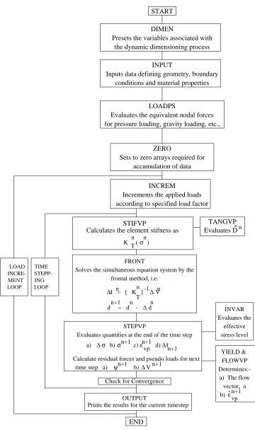
4.3 Flow Chart for three dimensional elasto-plastic program . . . 97
5.1 Comparison of experimental stress-strain behaviour of Ciba Araldite420 in tension with elastic-perfectly plastic modelling . . . 113
5.2 Single lap joint geometry and boundary conditions . . . 114
5.3 Finite element mesh of a single lap joint for H2/H1=1.0 and width b=1.0mm115 5.4 Normal and Shear stresses along the overlap length for Al/Al lap joint along the middle adhesive layer (applied load = 100N) . . . 116
5.5 Finite element mesh of a single lap joint for H2/H1=1.0 and width b=25.0mm117 5.6 Comparison of numerical and analytical solution for normal and shear stress distributions for various H2/H1 ratios at the centre of adhesive layer for an applied load of 10kN . . . 118
5.7 Comparison of numerical and analytical solution for normal and shear stress distributions for various H2/H1 ratios at the centre of adhesive layer for an applied load of 10kN . . . 119
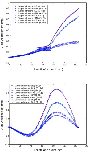
5.8 Comparison of deformation profiles for axial and vertical displacement in identical and non-identical adherends for linear and geometrical nonlinear solution (Applied load = 10kN) . . . 120
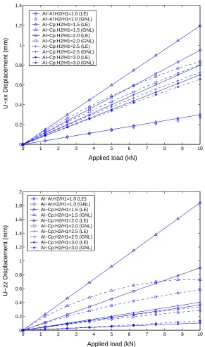
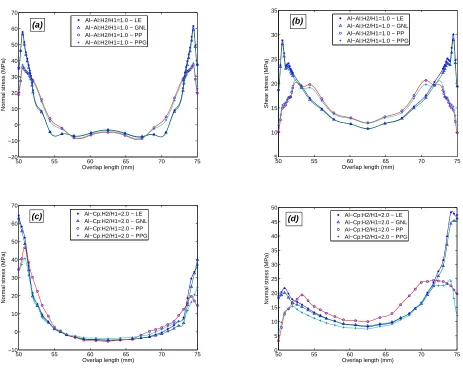
5.9 Linear and geometrical nonlinear axial and vertical displacement values for various H2/H1 ratios as a function of the applied load . . . 121 5.10 Comparison of Normal and shear stress distribution for different analyses
with identical and non-identical adherends along the middle adhesive layer: (a) Al −Al : H2/H1 = 1.0, (b) Al −Al : H2/H1 = 1.0, (c) Al −Cp :
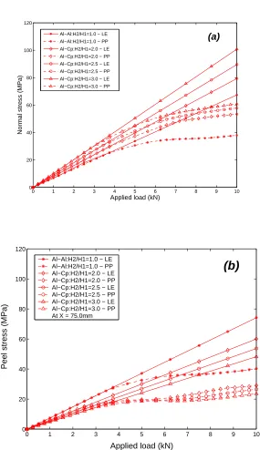
H2/H1 = 2.0 and (d) Al−Cp:H2/H1 = 2.0 (Applied load = 10.0kN) . 122 5.11 Variation of normal stresses at the overlap ends for the linear (LE) and
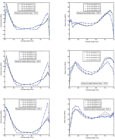
for the perfectly plastic (PP) analyses as a function of the applied load for different adherend thickness ratios: (a) atX = 50.0mmand (b) atX = 75.0mm . . . 123 5.12 Normal and Shear stress distributions at top, middle and bottom adhesive
layer for variousH2/H1 ratios for an applied load of 10.0kN (PPG Solution)124 5.13 Three dimensional normal and shear stress distributions at top, middle and
bottom adhesive layer for the joint with the thickness ration H2/H1 = 2.0 for an applied load of 10.0kN (PPG Solution) . . . 125 5.14 Anticlastic and Bending-Twisting effect on adherends and adhesive in single
lap joint . . . 126
6.1 (a) Dimensions of the butt-strap joint model butt-strap joint model with
adhesive thickness t = 1.0,3.0,5.0 and 10.0mm and (b) Superposition
pro-cedure . . . 141 6.2 (a) 2-D view of the FE model and (b) 3-D view of the FE model . . . 142 6.3 Comparison of experimental stress-strain behaviour of Plexus MA550 in
tension with Ramberg-Osgood modelling . . . 143 6.4 Validation of FE results with analytical solution for peel and shear stress
along the overlap of the butt-strap joint (a,b) t = 1mm, (c,d) t = 3mm
(Applied load = 10kN) . . . 144 6.5 Validation of FE results with analytical solution for peel and shear stress
along the overlap of the butt-strap joint (a,b)t= 5mmand (c,d)t= 10mm
(Applied load = 10kN) . . . 145 6.6 Comparison of experimental load-displacement curve with linear and
non-linear analysis for butt-strap joint with adhesive thickness: (a) t = 1mm,
(b) t= 3mm, (c) t= 5mmand (d) t= 10mm (Applied load = 10kN) . . . 146
6.7 Deformation profile along the length of the butt-strap joint at the bottom adhesive layer (a): Axial displacement for the adhesive thickness of 1mm, (b): Vertical displacement for the adhesive thickness of 1mm and (c): Ver-tical displacement in the central butt-joint gap for the different adhesive thicknesses (Applied load = 10kN; GMNL Solution) . . . 147 6.8 Detail of the deformed shape in the butt-strap joint and lateral contraction
6.9 Lateral displacement (Uyy) variation through the thickness of the butt-joint
for the adhesive thicknesses 5 & 10mm: (a) At front edge (y = 0.0mm), (b) At rear edge (y = 25.0mm) and (c) Three dimensional contour of Uyy
through the thickness of adhesive layer along the front edge of the joint (t= 10mm) (Applied load = 10kN) . . . 149 6.10 Peel and Shear stress distributions at top, middle and bottom adhesive
layer for butt-strap joint with adhesive thicknesses 1mm for different set of analyses (Applied load = 10kN) . . . 150 6.11 Maximum peel and shear stress Vs Applied load for butt-strap joint with
different adhesive thicknesses 1,3,5 and 10mm for the geometrical-material nonlinear (GMNL) analysis . . . 151 6.12 Three dimensional peel and shear stress distribution in the bottom interface
adhesive layer for butt-strap joint with adhesive thickness of 1mm (Applied load = 10kN) . . . 152 6.13 Peel and Shear stress distributions at top, middle and bottom adhesive
layer for butt-strap joint with adhesive thicknesses 1,3,5 and 10mm for the
geometrical-material nonlinear (GMNL) analysis (Applied load = 10kN) . 153
6.14 Failure modes seen in butt-strap joint with adhesive thickness 10mm [28] . 154
7.1 Finite element mesh of the hybrid joint structure . . . 165 7.2 Load Vs Deflection curve for the hybrid joint under static compression load 166 7.3 Notation for interface layers in hybrid joint where stress values are taken . 166 7.4 Normal stress (σzz) along the length of the hybrid joint at different planes
under in-plane compressive loading (Load = -120kN) . . . 167 7.5 Shear stress (τxz) along the length of the hybrid joint at different planes
under in-plane compressive loading (Load = -120kN) . . . 168 7.6 Through thickness variation of normal and shear stress along the plane
V43-V43 in the hybrid joint (Load = -120kN) . . . 169 7.7 Hybrid joint specimen under static compression test (Boyd et.al., 2004) . . 170 7.8 Normal stress (σzz) along the interface plane E-E and through the thickness
at the section V43-V43 in the hybrid joint under 4-point bending test (Load = 15kN) . . . 171 7.9 Axial stress (σxx) along the length of the joint at different planes subjected
to 4-point bending test (Load = 15 kN) . . . 172 7.10 Variation of axial stress (σxx) along the length of the joint at different
planes subjected to 4-point bending test (Load = 15 kN) . . . 172 7.11 Axial stress (σxx) along the different vertical planes subjected to 4-point
bending test (Load = 15 kN) . . . 173 7.12 Hybrid joint specimen under 4-pt bending test (Boyd et.al., 2004) . . . 174 7.13 Axial stress (σxx) along the length of the joint at different planes subjected
to flexural loading (Load = 1.5 kN) . . . 175 7.14 Axial stress (σxx) along the vertical planes subjected to flexural loading
C.1 Model of a Single element with boundary conditions . . . 199 C.2 Model of a cantilever beam for the linear Bench mark test . . . 200 C.3 Load/Displacement for bending and Stress/Strain for Axial load in
3.1 Material properties for different types of adhesives (Brede, 2001) . . . 62
5.1 Material Properties of adhesive and adherends . . . 112 5.2 Maximum normal stress values (MPa) obtained from various analyses along
the overlap length (mm) for different joint cases (X is as defined in figure 3a) . . . 112 5.3 Maximum shear stress values (MPa) obtained from various analyses along
the overlap length (mm) for different joint cases (X is as defined in figure 3a) . . . 112
6.1 Maximum values for axial displacement (Uxx) obtained from different set
of analyses (Applied load 10kN) . . . 140 6.2 Maximum values for vertical displacement (Uzz) obtained from different set
of analyses (Applied load 10kN) . . . 140 6.3 Maximum values for peel stress obtained from different set of analyses
(Applied load 10kN) . . . 140 6.4 Maximum values for shear stress obtained from different set of analyses
(Applied load 10kN) . . . 140
7.1 Material properties of adhesive and adherends considered in the hybrid joint164
u displacement vector with components u,v and w in x,y,z directions
J deformation gradient
J2′, J3′ second and third invariants of the deviatoric stress tensor Sij
J1 first stress invariant
ǫ Green’s strain
ǫo initial strain vector
εe, εvp elastic and viscoplastic strain components
σ vector of second Piola-Kirchoff stress
σm mean stress
σy effective yield stress
σ1, σ2, σ3 principal stresses
Sij deviatoric stress tensor
τoct octahedral stress
ρ density in the deformed state
N shape function
D elasticity matrix
E Young’s modulus
ν Poisson’s ratio
µ shear modulus
B strain-displacement matrix
Bo small strain displacement matrix
BL large strain displacement matrix
f vector of equivalent nodal forces
fp vector of applied nodal forces
fb force vector due to body forces
ft force vector due to surface tractions
fǫo force vector due to initial strain
fσo force vector due to initial stress
b body force
p surface traction
KT total tangent stiffness matrix
Ko small displacement stiffness matrix
KL initial or large displacement matrix
Kσ initial stress or geometric matrix
ξ, η, ζ curvilinear coordinates
δij Kronecker delta
F yield function
γ fluidity parameter
Q plastic potential
φ(F) flow function
Cijkl constitutive tensor for elastic materials
I′
1 first invariant of the general strain tensor
I′
2 second invariant of the general strain tensor
α time stepping parameter
ψ vector of residual force
λ ratio of compressive to tensile yield stress
∆tCR critical time step length
L adherend length
C overlap length
H adherend thickness
LE Linear Elastic solution
GE Geometric non-linear Elastic solution
VP Viscoplastic solution
Introduction
Adhesive bonding technology has expanded greatly in recent years as more and more
ad-vanced fibre reinforced composite materials are being utilized in structural applications.
Research and development of adhesive bonding technology has developed over the past
fifty years and has been mainly directed towards the requirements of the aerospace
indus-try. Today, progress is such that modern adhesives offer a joining technique of interest to
engineers in a far wider range of industries than just that of aircraft applications. These
include constructions in automobiles, trains, ship and marine structures, civil
construc-tion, rehabilitation of infrastructures etc. The civil and marine engineering sector are
becoming increasingly aware of adhesives as a method of joining. The use of adhesive
bonding as a joining method is an accepted means of attaining high structural efficiency
and improved fatigue life. One of the major advantages of adhesive bonding is that it
en-ables dissimilar materials to be joined without the need for modifications in the adherend
material as required when the joint is bolted/riveted. Adhesive bonding is attractive since
it allows for a more gradual diffused load transfer in to the structure, thus reducing the
localized stresses encountered in the use of bolts and rivets.
1.1
Adhesively Bonded Joints
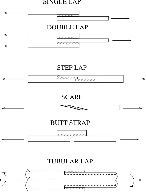
Structural adhesives are used in different types of joints. Commonly used adhesively
bonded joints are shown in fig 1.1. They are:
1. Single lap joint,
2. Double lap joint,
3. Step lap joint,
4. Scarf joint,
5. Butt strap joint and
6. Tubular lap joint.
Among these, single lap joint is often preferred and adopted due to its simplicity and ease
of fabrication. The single lap joint consists of two adherends and an adhesive layer joining
them together. The adherend may be either metallic or fiber reinforced composite.
1.1.1
Function and Failure of Adhesively Bonded Joints
Adhesives, being viscous, flow over the surface of a solid and because of their intimate
contact, interact with solid’s molecular forces. Then, as a result of the adhesive curing
process, they become strong solids which, retaining intimate contact with the surfaces,
hold them together. In general, the adhesives are not as strong as metal/composite
ad-herends and hence the adhesive interlayer will always tend to be the weakest link in a
bonded structure. Care is therefore needed to ensure that service stresses are well within
adhesive’s capabilities. This is normally achieved by providing a relatively large area in
bonding.
The failure of adhesively bonded joints can occur for any of the following reasons or
1. Cohesive failure within the adhesive,
2. Adhesive failure which occurs at interface of adhesive and adherend, and
3. Failure of adherends which also includes delamination in composite structures.
The other type of failure is progressive separation of adherends occuring by failure of the
adhesive under cyclic loading. The main cause of failure in adhesively bonded joints is
due to the brittle nature of adhesives. The adhesive is more prone to damage when the
structure is shock loaded and momentary distortion of adherend generates large peel and
cleavage forces that the adhesive may not be able to resist. Hence, an accurate analysis
of bonded joints is needed in order to determine the failure mode that could occur in a
joint for the worst anticipated combination of load.
1.1.2
Advantages and disadvantages of adhesive connections
The guide to the structural use of adhesives (1999) outlines the following advantages and
disadvantages in adhesive connections viz-a-viz other fastening techniques like bolts and
welding connections.
Advantages
• no damage to parent material (cf. drilling for bolts, etc.,)
• no damage to exposed surfaces (cf. spot-welding)
• fewer pieces required to form connections (cf. bolts, washers etc.,)
• smaller additional pieces, e.g. gusset plates, required to form connection (cf. bolted connections where minimum edge distances may determine plate dimensions)
• high effective stiffness of joint (cf. bolted connections which may slip)
• improved fatigue performance, because of reduction in stress concentrations
• tolerance to dimensional inaccuracies
• dissimilar materials can be joined readily
• elimination of bimetallic corrosion
• good noise and vibration damping
• efficient method of joining thin materials
• potential for simpler, faster fabrication
Disadvantages
• lack of experience of use when compared with traditional materials and methods
• properties will vary between different suppliers, and are constantly being ’improved’
• surface treatment required
• requires a high level of supervision by experienced staff
• generally requires a carefully controlled environment during assembly and curing of
a joint which is often difficult to achieve (particularly important for site assembly)
• possible Health and Safety implications
• time taken for connection to achieve full load carrying capacity (cf. bolting or
welding)
• completed connection not easily inspected
• strength limited under certain directions of loading; joints must be suitably designed
• connection can not be disassembled (cf. bolts)
• adhesive properties affected by temperature and humidity (cf. bolts)
• creep effects may be significant, particularly at elevated temperatures
• lack of agreed design guidance (applies to some materials only)
1.2
Sources of Nonlinearity
In many practical engineering problems, linear elastic analysis is not adequate. For an
ac-curate analysis one should consider the actual nonlinear behaviour. Nonlinearities in solid
mechanics arise from two distinct sources. One is due to the kinematics of deformation of
the body and the other from the constitutive behaviour(i.e., stress-strain relations). The
analysis in which the first type of nonlinearity is considered is called as geometric
nonlin-ear analysis, and those in which the second type is considered is a materially nonlinnonlin-ear
analysis.
1.2.1
Geometric Nonlinearity
If the load-displacement relationship is not linear for components made from materials of
linear properties, then this represents a geometric nonlinearity. In some structural
prob-lems it will be assumed that both displacement and strains developed in the structure
are small. In practical terms this means that the geometry of the elements is basically
unchanged during the loading process and that the first order, infinitesimal, linear strain
assumptions can be used. If the accurate determination of the displacements is needed,
geometric nonlinearity have to be considered while analysing the structures. Here the
strain displacement will not be linear but it will contain some quadratic terms. The
geo-metrically nonlinear analysis may be further classified based on the types of nonlinearities
considered. Two such cases are (i) large displacements, large rotations but small strains
and (ii) large displacements, large rotations but large strains. In the first case it is
as-sumed that the rotations of the elements are large but the extensions and changes of angle
between the elements are small. In the second case the extension of a element and the
angle changes between two elements are large, and the displacements and the rotations
Lagrangian formulation and Eulerian formulation. In the total Lagrangian formulation
all the variables are with reference to the original configuration, whereas in the Eulerian
formulation they are reffered to the current configuration.
1.2.2
Material nonlinearity
By far the most common sources of material nonlinearity in solid mechanics have been
divided into two independent groups of phenomena, described respectively by ’plasticity’
and ’creep’. For the first group, the classical theory of plasticity (Hill (1950), Perzyna
(1963,66)) provides a theoretical description of the stress-strain relationship. The
mate-rial performance is described by an irreversible straining which is not time dependent and
which can only be sustained till a certain level of stress has been reached. The second
group of phenomena includes all the time effects and results in the creep strains developed
at finite rate. Indeed, many structural materials, especially under high operating
tem-peratures, exhibits the phenomenon of creep; in which a redistribution of stress and/or
strain with time occurs which may be elastic or plastic in nature.
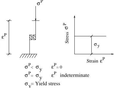
The concept of elasticity and plasticity are best illustrated by means of simple
uniax-ial stress-strain models.The components which combine to form these models are shown
in figures 1.2, 1.3 & 1.4 together with their corresponding stress-strain behaviour. Pure
elasticity is represented by a Hookean spring which has a linear relationship between stress
and strain. Pure plasticity is represented by a St.Venant’s slider which has zero strain
until the stress reaches the yield stress at which point we have what is known as perfect
plasticity, and for an elasto-plastic material the model consists of a Hookean spring and a
slider in series. For the uniaxial model shown in figure 1.4 the behaviour is purely elastic
until the stress level reaches the yield stress σy. When the slider yields and there is a
continuing deformation at constant stress, then it is impossible for the stress to exceed
the yield stress. If unloading takes place from the yielded state the strain path followed
is different from the loading path. Elasto-plastic behaviour is loading path dependant
on the yield surface by different routes then the plastic strains are different. This
ne-cessitates the use of an incremental form of plasticity in which the increments of plastic
strain throughout the loading history are determined and the total strain is obtained by
summation.
1.3
Selection of structural adhesives
Adhesives are versatile and their selection does not usually depend upon a single
prop-erty, but rather on a balance of several properties, which could be met by more than one
adhesive. Hence, the proper selection of adhesive becomes crucial from a performance
point of view. The basic chemical type of adhesive is very important, the choice being
from epoxide, acrylic, phenolic and polymeric materials. On strength requirements, one
should consider shear, cleavage and peel, impact strength, deformation and creep as the
main criteria for selection.
Guide to the structural use of adhesives (1999) gives guidelines of structural adhesives
and their application and design. Adhesive connections may be divided, very broadly,
into three categories, namely structural, semi-structural and non-structural. They may
be considered as follows:
• structural: the bonded joint carries all the load in a particular direction, at
ser-vice load or at both serser-vice and ultimate loads; failure in the bond line leads to a
significant change in the behaviour of the structure or in its load carrying capacity.
• semi-structural: the bonded joint is required chiefly to distribute the loads, the main
load carrying being by some other mechanism; failure in the bond line may result
in some change of behaviour under service loads but the ultimate strength will not
be affected.
• non-structural: the bonded joint is subjected to a nominal stress; the consequences
of failure in the bond line are structurally insignificant (though failure can still lead
A number of different aspects must be taken into account when considering the use of an
adhesive to form a structural connection. These include:
• design of the geometry of the joint
• selection of the adhesive itself, taking into account the materials to be joined, the stresses to be carried and the environmental conditions both during application,
curing and in service
• preparation of the surfaces to be joined
• workmanship
• Health and Safety and environmental considerations, both during assembly and
throughout the life of the structure
1.4
Aim and Scope of the Research
The aim of this study is to understand the nonlinear behaviour of different types of
adhesives that are increasingly being used for bonding marine structural components.
It is also aimed to study the influence of geometric and material nonlinearities on joint
deformations and adhesive stresses. Specific attention is devoted towards behaviour of
bonded joints with dissimilar adherends, joints with thick adhesive layers and hybrid
joints consisting of more than two different adherend materials. It is envisaged here
that nonlinear stress analyses could provide an enhanced understanding of the problem
pertaining to selection of suitable types of adhesives and dimensioning of joints.
1.4.1
Motivation
The focus of this study is related to the application of bonded joints in marine structural
components. The use of adhesive bonding in marine industry was initially restricted to
adoption of adhesive materials in structural components that transfer load, as an
al-ternative to mechanical fasteners, in the ship industry, has been slow compared to the
progress seen in other industries such as aerospace and automobile industries. The type
of materials used and the structural design practiced in the marine industry are different
from other fields and therefore, bonding technologies, say from aerospace field, cannot
be used directly in ship building or repair. Significant research has been directed
there-fore towards the exploration of FRP composites in a maritime environment (Mouritz et
al., 2001). The prime objective of adhesive bonding in ship structures is to use of light
weight composite materials wherever feasible; reduced superstructure and hull weight
can result in various advantages such as payload increase, speed range, stability and
re-duced maintenance. Light weight structures are predominantly used in super-structure,
advanced mast systems, bulkheads, decks, propellers, propulsion shafts and rudders in
different types of marine structures viz. patrol boats, hovercraft, corvettes, fishing boats
and fast boats. The major advantage of using adhesive bonding is joining different kind
of materials, metal-to-metal, metal-to-FRP, in the above mentioned vessels. Accordingly,
current research on joining dissimilar materials is reviewed and the scope for further study
is explained in the next chapter. Two case studies of bonded dissimilar joints that are
directly employed in marine industry are considered here; the analyses and the details are
provided in the following section.
As it will be discussed in the critical review of literature, current research trends in
numer-ically modelling the above mentioned case studies lack comprehensive approach when the
purpose is to study the load transfer mechanism among the structural components. This
warrants an improved set of methodology that could address all the issues concerning the
behaviour of bonded structural joint systems. Though there are good number of
commer-cial Finite Element Analysis (FEA) software packages to simulate the realistic state of
structural joint system, when it comes to characterisation of particular type of structural
adhesives it is found that the available commercial FEA packages have few shortcomings.
account for certain type of material nonlinear formulation in this case, a modified von
Mises equation and the Ramberg-Osgood equation to characterise a semi-rigid adhesive
material. Considering this fact and also in order to account for geometric and material
nonlinearities that exist in a bonded structures it has been decided to develop a finite
element code in a three dimensional domain. Development and utilisation of a in-built
FE code also provides better study of the numerical modelling at any stage of the
anal-ysis while the user of any commercial package will not have access to its source code to
monitor the numerical process.
1.5
Areas of investigation
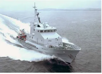
A three dimensional finite element analysis of two types of structural components is
pro-posed here. The first type of component relates to the numerical modelling of a butt-strap
joint system that is derived from the deck-to-superstructure connection, in a 34m long
Vosper Thornycroft (VT) Patrol craft that is shown in figure 1.5. An experimental
inves-tigation on the load carrying capacity of the deck-to-superstructure connection is carried
out by Jarry & Shenoi (2005) with the box joint and a single butt-strap joint specimen.
The numerical modelling that relates to experimental study on the strength of the
butt-strap joint is undertaken here. This joint consists of two dissimilar adherends, aluminium
and steel bonded by a semi-rigid adhesive material Plexus MA550.
The second study deals with stress analysis of a typical hybrid steel-GRP joint based
on the design for hangar to weather deck connections on the La Fayette class frigates,
currently in service in the French navy (figure 1.6). This hybrid joint consists of three
different materials, steel/GRP/Core bonded by an adhesive material. The geometry and
the loading conditions are shown in figure 1.7. As it will be revealed in the literature
review, the need for identifying the stress concentration locations that initiates failure in
the joint forms the main objective for this study.
a typical single lap joint consisting of non-identical adherends. This is for the reason
that the above mentioned case studies deal with dissimilar materials that are increasingly
explored in marine structures. Therefore, an idealised joint is chosen for the parametric
study. Actual joints will contain a spew fillet (see figure 1.8) of adhesive at the edges that
will influence the behaviour of the joint (Adamset al.,1997 and Frostig et al.,1999). For
computational efficiency and ease of building the 3-D models the effect of the spew fillet
is not considered in this work. The objectives and the methodology adopted for all three
types of problem are described in chapter 3.
1.6
Layout of thesis
For the ease of understanding, the lay-out of thesis is explained here.
• Chapter-1: Introduction - Presenting the basic information on adhesively bonded
joints, their advantages and disadvantages against the conventional mechanical
fas-tening methods. Aim and the scope of the research is outlined.
• Chapter-2: Critical Literature Review - Collection of review on bonded joints
covering lap joint theories, adhesive modelling, experimental/numerical modelling
followed by discussion.
• Chapter-3: Proposed Methodology - This chapter gives the background to the
problems considered and the methodology is proposed.
• Chapter-4: Solution procedures and FE formulation - This chapter presents
numerical implementation of geometric and material nonlinear equations in to a
finite element program code.
• Chapter-5: Study on adherend imbalances in single lap joint - This chapter
covers a study on adherend imbalances in a lap joint, addressing three dimensional
stresses based on a parametric study. Three dimensional effects and failure modes
• Chapter-6: Analysis of Butt-strap joint structures - This chapter deals with
performance of a butt-strap joint system bonded by semi-rigid adhesive that forms
a structural component in the superstructure of a Patrol craft.
• Chapter-7: Stress analysis of GRP-Steel hybrid joints- This chapter attempts
to identify the critical stress locations that occur in a GRP-Steel hybrid that
trans-fers significant load in a weather-to-deck-superstructure of an helicopter hangar in
a French navy Lafayetteclass frigate.
• Chapter-8: Discussion - Provides over all discussion on the formulation of the FE
code and the key results obtained from the analyses.
• Chapter-9: Conclusion - Concludes with the overview of this thesis, followed by
0
1
0000 0000
1111 1111
0000
1111
0 0
1 1
0000
1111
0000
1111
00000
11111
00000
11111
0000
1111
0000
1111
0000 0000
1111 1111
SINGLE LAP
DOUBLE LAP
BUTT STRAP
TUBULAR LAP STEP LAP
[image:32.612.189.438.208.534.2]SCARF
= D σe eε ε σe e e e σ Stress ε Strain
Figure 1.2: Uniaxial stress-strain model showing Elastic behaviour
P
P
P
σ < σ y P
σ = σ y
= Yield stress y σ σ ε εP = 0
εP indeterminate
P
σ
Stress
Strain εP
[image:33.612.211.404.99.239.2]σ y
Figure 1.3: Uniaxial stress-strain model showing Plastic behaviour
ε
σ
εe
ε
σ y
Stress
εe ε Strain ε
ε = ε + εe P
ε = e D-1σ
p
σ<σ y
εp= 0 if
σ y
σ=
εp= indeterminate if
p p e y Stress σ Strain ε ε
[image:33.612.215.406.283.431.2]000000000 000000000
111111111 111111111
0 0 0 0 0 0 0 0 0
1 1 1 1 1 1 1 1 1
00000
11111
0 0
1 1
000000000
111111111 X
Z
80 x 80 x 6 Al 6082 Box 80 x 5 Al 5083
6mm flat steel plate Plexus MA550
Adhesive
90 x 90 x 5 Steel Box
Clamp
[image:34.612.133.491.114.374.2]P P
Figure 1.6: Helicopter hanger on the French La Fayette class frigate (Courtesy of DCN) 000000000000000000000000000000000000 000000000000000000000000000000000000 000000000000000000000000000000000000 000000000000000000000000000000000000 000000000000000000000000000000000000 000000000000000000000000000000000000 000000000000000000000000000000000000 000000000000000000000000000000000000 111111111111111111111111111111111111 111111111111111111111111111111111111 111111111111111111111111111111111111 111111111111111111111111111111111111 111111111111111111111111111111111111 111111111111111111111111111111111111 111111111111111111111111111111111111 111111111111111111111111111111111111 00 00 11 11 00 00 11 11 0 1 0
1 01
00 11 0 0 0 0 0 0 0 0 1 1 1 1 1 1 1 1 00
1100110011
0 1 0 1 0 0 0 1 1 1 0 0 1 1 0 1 0 1 000000000000000000000000000000000000 111111111111111111111111111111111111 000000000000000000000000000000000000 000000000000000000000000000000000000 000000000000000000000000000000000000 000000000000000000000000000000000000 000000000000000000000000000000000000 000000000000000000000000000000000000 000000000000000000000000000000000000 000000000000000000000000000000000000 111111111111111111111111111111111111 111111111111111111111111111111111111 111111111111111111111111111111111111 111111111111111111111111111111111111 111111111111111111111111111111111111 111111111111111111111111111111111111 111111111111111111111111111111111111 111111111111111111111111111111111111 000000000000000000000000000000000000 000000000000000000000000000000000000 111111111111111111111111111111111111 111111111111111111111111111111111111 00 00 11 11 000000000000000000000 111111111111111111111 00 00 00 11 11 11 0 1 000000000000000000000000000000000000 000000000000000000000000000000000000 000000000000000000000000000000000000 000000000000000000000000000000000000 000000000000000000000000000000000000 000000000000000000000000000000000000 000000000000000000000000000000000000 000000000000000000000000000000000000 111111111111111111111111111111111111 111111111111111111111111111111111111 111111111111111111111111111111111111 111111111111111111111111111111111111 111111111111111111111111111111111111 111111111111111111111111111111111111 111111111111111111111111111111111111 111111111111111111111111111111111111 000000000000000000000000000000000000 111111111111111111111111111111111111 0000 1111 00 00 11 11 00 00 11 11 00 00 11 11 00 00 11 11 00 00 11 11 00 00 11 11 00 00 11 11 00 00 11 11 00 00 11 11 00 00 11 11 00 00 11 11 00 00 11 11 00 00 11 11 00 00 11 11 00 00 11 11 00 00 11 11 00 00 11 11 00 00 11 11 00 00 11 11 00 00 11 11 00 00 11 11 00 00 11 11 00 00 11 11 00 00 11 11 00 00 11 11 00 00 11 11 00 00 11 11 00 00 11 11 00 00 11 11 00 00 11 11 00 00 11 11 00 00 11 11 0 1 P 225 60 70 120 125 38 4 4 5.4 P P
60 65 65 60
P
-P Laminated FRP Skin
End-grain Balsa core
Adhesive bonding Steel plate
Hybrid joint under compression loading
Hybrid joint under 4-point bending
Hybrid joint under flexural loading
L C L
B
x y z
Unloaded Adherend
Loaded Adherend H2
h H1
Top interface layer
Adhesive middle layer
Bottom interface layer P
P
P
eccentricity (e)
τ
z
xz
ADHESIVE
σ
Normal stress
Shear stress
Overlap end (B)
overlap end (A) spew fillet
Critical Literature Review
2.1
Introduction
This chapter reviews the research work on bonded joints under the categories of lap
joint theories, adhesive modelling, experimental work and numerical approach/modelling,
followed by discussion for each section. The final section outlines the contribution of the
reviewed papers in the context of the current research and identifies the weaknesses with
respect to modelling of adhesives and to analyses of bonded connections. This offers scope
for the definition of new research for further development which is presented in the next
chapter.
2.2
Lap joint theories
2.2.1
Review
The earliest work on adhesive bonded joints, and in particular lap joints, has been
at-tributed to Volkerson (1938), although in reality the analysis was for riveted plates. His
work addressed ’Differential shear’ and centered on a ’shear lag’ model that neglected the
effects of joint eccentricity, and considered only adhesive shear deformation and adherend
deforms in tension, for homogeneous and isotropic material. The main limitation of this
model is that it does not take into account the bending due to eccentricity of the load
direction. The analysis found that the thicker the adhesive layer, the higher the strength.
However, one has to be reminded that adhesive thickness cannot be increased indefinitely
and that beyond a certain thickness, it cannot be counted as an adhesive layer, but as
a third material in the structure in which case an anisotropic plate analysis should be
applied. Further, this result is not supported by experimental evidence which shows that
thicker bond lines give lower strengths (Adams and Grant, 1993).
As mentioned above the theory developed by Volkerson (1938) takes no account of the fact
that First, the directions of two forces are not collinear which leads to a bending moment
being applied to the joint in addition to the in-plane tension, causing the adherends bend,
allowing the joint to rotate. Goland and Reissner (1944) used a beam-on-elastic
founda-tion that took rotafounda-tion into account by using a bending moment factork, which relates to
the resultant moment. In this paper, the approach was in three parts. In the first, it was
shown that the bending moment is not transmitted integrally and, therefore, a bending
coefficient k is derived. In the second part, the assumption was made that the adhesive
is relatively rigid, and in the third part, it was assumed that the adhesive is relatively
flexible, where it is known as Goland and Reissner’s second theory. The second
theo-retical approximation is applicable to metal-to-metal adhesively bonded joints, whereas
the first approximation assumes the joint to be monolithic. The second theory also has
a limitation in the sense that it neglects the shear deformation and peel stresses across
the adherend thickness. Furthermore, it does not take into account the fact that shear
should be zero at the joint edge. The proposed methods are valid only for material with
elastic behaviour, whereas most adhesives present elasto-plastic behaviour (Hart-Smith,
1973). The Goland-Reissner analysis is limited to situations in which the adherends are
identical, the joint-edge loads are not in equilibrium, and the stresses across the adhesive
layer are constant.
Cornell (1953) presented a variation and extension of Goland and Reissner’s approach
cement layer is an infinite number of shear and tension springs. He used Euler’s beam
theory to describe the adhrends. Good agreement was found with photoelastic
experi-mental results when applying bending, axial and shear loading, and also highlights the
importance of fillet radius. It should be stressed that this method is more suitable to
assess fatigue stress rather than static stress because of the assumption that the adhesive
layer is modelled as an infinite number of springs. The only limitation of the method is
found in the assumption that adhesive stiffness is negligible.
Lubkin (1957) suggested a theory for scarf joints having a negligibly thin adhesive layer.
Hence it was developed on the assumption of uniform stress/strain across its thickness.
Based on the semi-inverse method, he showed that the stresses were constant along the
joint for all scarf angles, provided the adherends have the same elastic properties for the
tensile load. For non-identical adherends, he showed that a scarf angle can be determined
which provides homogeneous elongation of the adhesive layer. Hart-Smith (1974)
de-scribed the scarf joint as mathematically the most difficult to solve, due to the governing
differential equations not having standard closed form integrals. Scarf joints of dissimilar
adherends have been analysed by Wah (1976a,1976b) who highlighted a marked effect of
longitudinal stress and observed that the maximum stress occurs near the stiffer adherend.
He also suggested an approach using Eigen solutions for determining shear and tensile
stresses developed under pure bending.
Allman (1977) has derived a solution that satisfies the stress free boundary condition
for a symmetric lap joint. His elastic stress analysis is based on the strain energy density
of a particular joint. The adherends were modelled to account for bending, shear and
nor-mal stresses. Like Goland and Reissner (1944), Allman also set the adhesive shear stress
at the overlap ends to zero. He allowed for a linear variation of the peel stress across the
adhesive thickness, although the adhesive shear stress was treated as constant through
the thickness. In spite of this limitation, this is an improvement on earlier theories. He
therefore preferred approximate numerical techniques, should this situation arise.
Further extension of Goland and Reissner’s model, through use of a more complete
shear-strain/displacement equation for the adhesive layer, is illustrated by Ojalvo and Eidinoff
(1978). Ojalvo and Eidinoff’s theory predicts the variation of shear stress through the
bond thickness, even for thin layers. This through-the-bond-thickness variation of shear
stress identifies two anti-symmetrical adherend-bond interface points at which the shear
stresses are highest. The results also highlight the differences in stresses obtained by
theories which include and those which neglect the effect of bond thickness.
On transverse stresses in bonded joints, Adams and Peppiatt (1973) have shown the
existence of significant stress across the width of an adhesive joint. They considered the
existence of shear stresses in the adhesive layer and direct stresses in the adherends acting
at right angles to the direction of the applied load, these stresses being caused by
Pois-son’s ratio strains in the adherends. Edge effects in the joints can be complicated by the
presence of spew fillets that occur when excessive resin is squeezed from the joint. Adams
and Peppiatt (1974) have observed that their presence is actually beneficial, reducing
adhesive stress by up to 30%.
With the limitations in the various classical theories mentioned above, Hart-Smith (1973)
extended the Goland and Reissner model to treat joints with elastic-plastic adhesives and
to determine the critical bending moments in adherends at the end of the overlap. He also
addressed the stiffness imbalance between adherends and the influence of laminated
com-posite adherends (as distinct from isotropic metal adherends). The elastic-plastic theory
used by Hart-Smith predicts an increase in joint strength and was shown to be capable
of explaining premature failure predictions found when using linear elastic analyses. The
quantitative effects of stiffness imbalance were also accounted for. Three distinct and
characteristic failure modes are predicted. The first is that of failure of adherend just
stresses and bonding stresses resulting from eccentricity in the load paths. The second
mode is the failure of the adhesive layer in shear, though the inclusion of plasticity in the
analysis has demonstrated that this potential failure mode is extremely rare in structural
practice. The third failure mode may be manifest in either of two forms and is associated
with the adhesive peel stresses. With the FRP composite adherends, the interlaminar
tension strength is so much less than the peel strength of good structural adhesives that
the failure occurs within the continuous laminate at the ends of the joint.
A comparison of different lap joint theories mentioned above were studied by
Carpen-ter (1991). He took into account the earlier assumptions from Goland and Reissner’s
model. The effect of a given assumption on predicted adhesive stress is difficult to
de-termine with a differential equation approach. A set of control parameters prescribing
the kind of assumptions for various cases and their influence on prediction of stresses are
discussed. In the case of membrane shear-bending study, the maximum adhesive peel
stress was affected very little by most assumptions. But factors like shear deformation of
adherends, plane stress/strain option and whether a consistent shear stress-strain
equa-tion is employed, have a bearing on the maximum adhesive peel stress. Finite element
modelling of joints is also considered and the author says that using one row of isotropic
adhesive elements gives results comparable to that of lap joint theories. More rows of
adhesive element in the model results in a further increase in maximum adhesive peel and
shear stresses. This highlights the refinement of the mesh grid in the model, which
en-hances idealization of the joint. In the same vein, it also shows a deviation from predicted
results from lap joint theories. Carpenter concludes that the maximum adhesive stress
derived from these theories are artificial stresses, which in no way correspond to those
obtained from a solution of the linearized equations of elasticity, which predict a singular
stress state at the corners of adhesive-adherend interfaces.
Improved theoretical solutions for adhesively bonded single and double-lap joints are
theoretical analyses by assuming a linear shear stress (strain) through the thickness of
the adherends, which earlier theories had not accounted for. This assumption is quite
appropriate for laminated composite adherends in particular, and the experimental and
numerical results have been reported to be more closely correlated.
2.2.2
Discussion
The above review has illustrated that the development of theoretical models of the
ad-hesive joint has taken over five decades. Volkersen (1938) first proposed a simple shear
deformation in the adhesive layer which neglected the eccentricity in the load-path. Later
Goland and Reissner (1944) postulated a beam-on-elastic foundation, simulating the joint
as consisting of two beams bonded with a negligible adhesive layer (i.e. ignoring the
pres-ence of the adhesive layer). They also assumed the non-existpres-ence of axial stress and that
other stresses would not vary through the thickness of the adhesive layer. Most
impor-tantly they took account of rotation due to eccentricity in load-direction which Volkersen
(1938) had not considered.
Cornell et al.(1953) modelled the adherends as two Euler beams and the adhesive as
an infinite number of springs. The results may perhaps be suitable for fatigue stress,
given that the adhesive layer is modelled as springs. Allman (1977) presented an elastic
stress analysis based on the strain energy density of a particular joint. The effects of
bending, stretching and shearing of the adherends were included, and the shearing and
tearing action accounted for. He found that the shear stress concentration is 11% higher
than that of Goland and Reissner’s first analysis while the the average peel stress at the
joint edge is 67% lower. All these lap joint theories have assumed zero adhesive shear
stress. Ojalvo and Eidinoff (1978) upgraded the theory by considering linear variation of
longitudinal and transverse deflections through the adhesive between the adherends.
improves our understanding of the sources of non-uniform load transfer, adherend
sensi-tivity, stiffness imbalance and thermal mismatch. He extended the Goland and Reissner
model to treat joints with elastic-plastic adhesives. He determined also the critical
bend-ing moment in adherends at the end of overlap and discussed the possible three failure
modes in the bonded joint. On the other hand, the significance of transverse stresses and
the existence of stress gradients through the thickness of the adhesive layer, close to the
joint edges were observed by Adams and Peppiatt (1973,1974).
Lap joint theories proposed earlier were compared by Carpenter (1991). His own finite
element model suggested that a refined mesh of adhesive layer leads to enhanced
maxi-mum adhesive peel and shear stresses and deviated substantially from those predicted by
the above theories. The common feature of these theories is that simplifying assumptions
are made concerning the behaviour of the adherends and adhesive. These assumptions
remove the stress singularities which occur at the edges of the interfaces of the adhesive
and adherends and yield differential equations which can be solved to yield the stresses in
the adhesive. Maximum adhesive stresses from these solutions can then be used in joint
design.
Further, it can be said that various pioneer authors have compromised on important
char-acteristics of the bonded joint factors such as load eccentricity, bending moment factor,
variation of stresses through the thickness of the adhesive layer, adherend-adhesive shear
stresses. These authors also modelled adherends as beams/plates, ignoring transverse
normal/shear stress gradient in an attempt to arrive at the solution for the differential
equation. But a review of the literature right from Volkersen (1938) shows that there is
2.3
Modelling of Adhesives
2.3.1
Review
This section briefly outlines the different modelling techniques adopted for adhesive
ma-terials in bonded joints. Based on the nature and properties of adhesives, there are
various constitutive relations and different types of failure criteria accounted for in
nu-merical studies. Elastic and inelastic behaviour of adhesives in joints are also considered
by some researchers. In this section, the focus is on the type of modelling used and the
failure criteria, followed in predicting the strength of adhesives. To begin with, Ojalvo
and Eidinoff (1978) have defined an adhesive model by a set of shear-strain/displacement
equations and accounted for variation of through thickness stress in the adhesive layer
while formulating differential equations based on Goland and Reissner’s theory. The
the-ory of Goland and Reissner is extended here by a more complete relation between shear
strain and displacement corresponding to linearly varying displacements through the
ad-hesive thickness. Based on Ojalvo and Eidinoff’s work, an FE model for single lap joint
was developed by Lin and Lin (1993), which includes linear variation of longitudinal and
transverse deflection in adhesive material. The adherend is modelled as a Timoshenko
beam and hence, the realistic behaviour of the joint is restricted by beam theory. The
results showed that maximum shear and normal stress increase as adhesive thickness is
reduced which is supported by three dimensional FE analysis by Pandey and Narasimhan
(2001).
Mortensen and Thomsen (1997,2002a,b) have considered adhesive material as linear
elas-tic, inelastic tension/compression springs, and adopted plate theory for adherends that
care considered as beams or wide plates in cylindrical bending. Nonlinear adhesive
prop-erties are included by using a tangent modulus approach. In their latter paper, they have
suggested the use of adhesive with relatively low values of elastic shear and tensile moduli,
i.e. flexible adhesive. These authors have also used modified von Mises criterion as
structural adhesive is dependent on both deviatoric and hydrostatic stress components. A
consequence of this phenomenon there is a difference between the yield stress in uniaxial
tension and compression. This ratio is incorporated in the von Mises equation. For most
structural adhesive, this criterion is appropriate.
Crocombe and Bigwood (1992) also attempted the modelling of nonlinear behaviour of
adhesive by considering a coupled set of shear and tension springs, with adherends as
wide cylindrically bent plates. The Finite Difference method was used and they employed
full elasto-plastic analysis for the full joint. While the adherend was accounted by the
von Mises equation, the adhesive was modelled by a modified Prager model. This model
however, was validated for one-dimensional problems only.
While the above papers treat the adhesive as a set of linear/nonlinear shear and
ten-sion/compression springs, other researchers have modelled them as proper linear/nonlinear
plane/solid elements. This approach is more appropriate than the spring analogy, which
accounts for one-dimensionality. Adams and Peppiatt (1974) adopted linear behaviour
for plane strain adhesive elements in their single/double lap joints. Mori and Sugibayashi
(1992) adopted linear behaviour for their stepped-lap joint plane strain analysis and used
von Mises criterion for both adhesive and adherends. The stress-strain behaviour of
ad-hesive FM-73 shows nonlinearity but it is not included in their analysis.
Roy and Reddy (1988a) analysed the single lap joint by considering geometric
nonlin-earity and by representing the adhesive as a linear plane strain element. In their other
paper (1988b), the viscoelasticity of adhesive FM-73 is studied together, with diffusion
in bonded joints. The suggested FE model incorporates Schapery’s nonlinear
viscoelas-tic constitutive relation and the nonlinear diffusion model of Lefebvre. This nonlinear
viscoelastic behaviour is typified by an accelerated and stress-enhanced creep. Earlier,
Delale and Erdogon (1981) assumed the adhesive to be a viscoelastic material and showed
than the corresponding shear stress but also decays more slowly.
Li et al. (1999) have carried out nonlinear FE analysis to study stress and strain
dis-tributions across the adhesive thickness in composite single lap joints. Two types of
epoxy adhesives, flexible and rigid were considered; both were assumed to have linear
stress-strain behaviour. Failure in the joint was attributed to crack initiation in the
in-terface layer and the results suggests that more rigid adhesive would lead to considerably
lower strains within the adhesive layer. The same authors, while comparing the strength
of flexible and rigid adhesives in their most recent paper (Li and Lee, 2001), have observed
that the peel and shear stresses was influenced by the modulus of the bonding adhesive:
the stiffer the adhesive, the higher the stresses .
Three dimensional modelling of adhesive material as a solid brick element is attempted
by Andruet et al. (2001) and by Pandey and Narasimhan (2001). While the former
accounts for only the linear behaviour of the adhesive, the latter have developed a
vis-coplastic constitutive relation and considered the modified von Mises yield function. The
stress-strain relation of the adhesive is represented by Ramberg-Osgood relation as
de-scribed by Ramamurthy and Rao (1978). Tonget al. (1995) have attempted to establish
the relationship between surface displacement and adhesive peel stress in bonded double
lap joints. For this, they have done elastic/plastic material nonlinear analysis and have
used the von Mises yield criterion. But they have considered only linear elasticity in
adhesive/adherend to validate their theoretical relation of peel stress with surface
dis-placement, obtained from holographic interferometry. Further work by Sheppard et al.
(1998), has developed strain based von Mises equation as a ’cohesive’ failure criterion in
assessing the damage zone for the bonded joints.
Wang et al. (2004) have tried modelling rubber-like flexible adhesive (PU) using the
theory of hyperelastic continua. The strain energy based hypothesis of Beltrami and the