Luby Transform Coding Aided Bit-Interleaved Coded
Modulation for the Wireless Internet
R. Y. S. Tee, T. D. Nguyen, S. X. Ng, L-L. Yang and L. Hanzo
School of ECS, University of Southampton, SO17 1BJ, UK.
http://www-mobile.ecs.soton.ac.uk
Abstract— Bit-Interleaved Coded Modulation using Iterative Decoding(BICM-ID) is amalgamated with Luby Transform (LT) coding. The resultant joint design of the physical and data link layer substantially improves the attainable Bit Error Rate (BER) performance. A Cyclic Redundancy Check (CRC) combined with a novel Log-Likelihood Ratio (LLR) based packet reliability estimation method is proposed for the sake of detecting and disposing of erroneous packets. Subsequently, bit-by-bit LT decoding is proposed, which facilitates a further BER improvement at a lower number of BICM-ID iterations. Finally, we revisit the pseudo random generator function used for designing the LT generator matrix.
I. INTRODUCTION
The classic data link layer technique of mitigating the wire-less channel impairments is to employ Automatic Repeat Requests (ARQ). Naturally, this method requires additional bandwidth for the retransmission of data, once a corrupted packet is received which necessitates a feedback channel. By contrast, in this study we dispense with the feedback channel by jointly designing the physical and data link layer.
More explicitly, Luby Transform (LT) [1] coding is employed for eliminating the feedback required by ARQ aided transmissions. LT coding was originally designed for the Binary Erasure Channel (BEC), which requires the transmission of redundant packets for the sake of recovering the original source packets. We propose to amalgamate LT coding with Bit-Interleaved Coded Modulation using Iterative Decoding (BICM-ID) [2] for the sake of mitigating wireless communication channel effects.
The novelty of this paper is that instead of using a simple serial concatenated LT and BICM-ID scheme, we intrinsically amalgamate LT coding and BICM-ID by creating an exchange of extrinsic information between them. A Cyclic Redundancy Check (CRC) is used for detecting the presence of any erroneous packets. A further novel improvement suggested is that an LLR based packet reliability estimation is introduced. Extrinsic Information Transfer (EXIT) charts are used by the proposed LLR-based packet reliability estimation scheme. This potentially enhances the error checking capability, especially at higher Signal to Noise Ratios (SNR) and hence may eliminate the potential redundancy introduced by the CRC overhead.
Error propagation across LT packets encountered during packet decoding may cause failure in LT decoding. Hence, as a counter mea-sure, in this paper we introduce a bit-by-bit LT decoding technique by exploiting the LLR estimations provided by the associated BICM-ID decoder. The advantages are two fold : 1) we reduce the probability of occurrence of erroneous packets which would otherwise have to be discarded. 2) we mitigate the probability of potential error propagation inflicted by erroneous packets. When corrupted bits are in the same index location of difference source packets, we can readily discard them with the aid of LT bit-by-bit decoding as long as the number of received packets contain the minimum number of redundancy. We further propose a novel pseudo-random generator [3] for creating the LT encoded packets, which will allow us to reduce the proportion of redundant packet required for successful LT decoding. The rest of this contribution is organized as follows. Section II provides an overview of our system, outlining our joint design of
The financial support of the EPSRC, UK, and that of the European Union is gratefully acknowledged.
LT and BICM-ID coding. The proposed CRC and LLR-basd packet reliability estimation scheme designed with the aid of EXIT charts are detailed in Section III. Section IV describes the bit-by-bit LT decoding as well as the pseudo-random LT generator matrix approach. Section V quantifies the achievable performance of this novel jointly design scheme, while our conclusions are presented in Section VI.
II. SYSTEMOVERVIEW
The schematic of the joint LT BICM-ID arrangement is shown in Figure 1. Consider a single-transmit and single-receive antenna aided system seen in Figure 1, when the source data file to be
transmitted consists of K number of packets. The LT decoder
will require the transmission of K = K +E number of LT
encoded packets requiring E redundant packets for the success of
the decoding process. After transmission over the BEC imposing an erasure probability ofPe,(Pe.K)number of the original LT encoded packets will be obliterated.
At the physical layer, we deal with frame-by-fame transmission. Each transmission frame consists of a number of packets. A transmis-sion packet is in turn broken intoSnumber of symbols. Each
BICM-ID source symbol is comprised of ksource bits and the BICM-ID
encoded symbols have n= k+ 1encoded bits. The encoded bits
are mapped to anM-QAM constellation before transmission over an
AWGN channel.
Encoder
16QAM BICM−ID
Decoder LT Decoder CRC
Controller
CRC Detector
AWGN Channel
LLR soft value Feedback Channel
Internet BEC Encoder
LT Upper Layer
from Source
Upper Layer to Destination BICM−ID
LLR Estimator
Buffer
[image:1.612.319.554.410.487.2]E-value
Fig. 1. System structure of the joint design of LT and BICM-ID.
At the receiver seen in Figure 1, BICM-ID decoder receivesa prioi
information from channel demodulator and output a extrinsic
in-formation which is to be fed back to the demodulator for iterative decoding. The sufficiently reliable output bits are then passed to the LT decoder after a number of BICM-ID iterations. We assume here that the perfectly sychronized LT encoder and LT decoder are capable of identifying the indices of the lost packets. The CRC controller inserts CRC bits into the LT encoded packets while the CRC detector extracts the CRC bits and verifies the detectable error inside each packet.
III. ESTIMATIONSCHEME
The LT decoder using the message passing algorithm [1] is inherently sensitive to error propagation. An erroneous packet which contains corrupted bits may propagate the errors from the source nodes of the LT encoder’s generator matrix to check nodes, when modulo-2 operations are performed during the message passing decoding [4]. Further related designs were proposed in [5]. By
ensuring that a minimum of E redundant packet is available, we
associated error propagation. This can be achieved by discarding erroneous packets, as and when corrupted bits are detected in a packet. Subsequently we employ the CRC-12 code, which is widely used in telecommunication systems for error detection in conjunction with the generator polynomial x12+x11+x3+x2+x+ 1[6]. This error detection approach improves the system performance but introduces an overhead. Observe in Figure 1 that the CRC controller injects the CRC bits into the BICM-ID encoded 16QAM stream, before transmitting them over the AWGN contaminated BEC. In this paper, we map four bits to the 16 QAM constellation points. The received CRC bits are extracted and are used for detecting the presence of any erroneous bits.
As an alternative, the joint design of LLR-based perfect reliability estimation using BICM-ID has the ability to further improve the system’s performance. This potentially allow us to eliminate the CRC overhead bits, while maintaining reliable detection especially at a high SNR. As seen in Figure 1, the soft LLR output of the BICM-ID decoder is stored in the LLR estimator’s buffer. The BICM-BICM-ID decoder will set a threshold value for the LLRs, in order to determine which LT packet may contain erroneous bits. Based on their LLR values, each of the corresponding bit is flagged with a ’0’ or ’1’ to indicate a reliable or unreliable bit, which allows the LT decoder to mitigate the associated error propagation effects during the decoding process. A feedback signal is provided by the LT decoder to control the LLR estimator’s threshold for the sake of achieving the highest possible detection accuracy.
Demod π
π−1
BICMID Decoder
Extrinsic LLR to LT
Hard Decoded Bits Channel LEDemod
LA
Demod LEDec LA
Dec
[image:2.612.320.555.50.223.2]Pchan LDataExtDec
[image:2.612.338.529.512.623.2]Fig. 2. BICM-ID system structure.
Figure 2 shows the basic BICM-ID scheme, where π and
π−1 denote the interleaver and deinterleaver. The channel’s out-put information is passed to the demodulator, which receives the
a priori LLRsLA
Demod from the BICM-ID decoder and provides the extrinsic LLRs LE
Demod for the decoder. The channel
de-coder of Figure 2 receives the a prioiri LLRs LA
Dec from the
demodulator and outputs the extrinsic LLRs LE
Dec in order to
perform iterative decoding by exchanging theextrinsicinformation between the BICM-ID decoder and demodulator. The reliability of the demodulator decisions depends on the channel’s Symbol-to-Noise
Ratio SNR and on the a priori information LADemod, yielding
LE
Demod=f(LADemod|SN Rchan).By contrast, the reliability of the
channel decoder’s decisions depends solely on thea priori LLRs
received from the demodulator, since it only has a single input and hence it is not directly dependent on the SNR [7], i.e. theextrinsic
mutual informationIE
Dec=f(IDecA )andIDecDataExt=g(IDecA ). Using the technique proposed in [7] we are capable of plotting both the EXIT chart and the corresponding BER values are plotted in Figure 3 assuming that the variance of the Gaussian distributed of the decoder
output σ2 is known [7]. The system parameters used in this paper
are detailed in Table I.
BICM-ID code rate R=3/4
Modulation 16QAM
Number of source packets 10000
Number of transmitted packets 13000
Number of bits per source packet 165
BEC erasure probability Pe=0.1
LT degree of distribution Improved Robust Dist. (IRD)
TABLE I SYSTEM PARAMETERS.
More explicitly, Figure 3 details the EXIT characteristics of both the demodulator and of the BICM-ID decoder. The nine dotted lines
0 0.1 0.2 0.3 0.4 0.5 0.6 0.7 0.8 0.9 1
0 0.1 0.2 0.3 0.4 0.5 0.6 0.7 0.8 0.9 1 10-5
10-4
10-3
10-2
10-1
100
IA
(Demod), I
E
(Dec)
BER
IE(Demod), IA(Dec)
1dB 2dB 3dB memory-3
0 0.1 0.2 0.3 0.4 0.5 0.6 0.7 0.8 0.9 1
0 0.1 0.2 0.3 0.4 0.5 0.6 0.7 0.8 0.9 1 10-5
10-4
10-3
10-2
10-1
100
IA
(Demod), I
E
(Dec)
BER
IE(Demod), IA(Dec)
1dB 2dB 3dB memory-3
memory-5
0 0.1 0.2 0.3 0.4 0.5 0.6 0.7 0.8 0.9 1
0 0.1 0.2 0.3 0.4 0.5 0.6 0.7 0.8 0.9 1 10-5
10-4
10-3
10-2
10-1
100
IA
(Demod), I
E
(Dec)
BER
IE(Demod), IA(Dec)
1dB 2dB 3dB memory-3
memory-5 memory-6
0 0.1 0.2 0.3 0.4 0.5 0.6 0.7 0.8 0.9 1
0 0.1 0.2 0.3 0.4 0.5 0.6 0.7 0.8 0.9 1 10-5
10-4
10-3
10-2
10-1
100
IA
(Demod), I
E
(Dec)
BER
IE(Demod), IA(Dec)
1dB 2dB 3dB memory-3
memory-5 memory-6
0 0.1 0.2 0.3 0.4 0.5 0.6 0.7 0.8 0.9 1
0 0.1 0.2 0.3 0.4 0.5 0.6 0.7 0.8 0.9 1 10-5
10-4
10-3
10-2
10-1
100
IA
(Demod), I
E
(Dec)
BER
IE(Demod), IA(Dec)
1dB 2dB 3dB memory-3
memory-5 memory-6
0 0.1 0.2 0.3 0.4 0.5 0.6 0.7 0.8 0.9 1
0 0.1 0.2 0.3 0.4 0.5 0.6 0.7 0.8 0.9 1 10-5
10-4
10-3
10-2
10-1
100
IA
(Demod), I
E
(Dec)
BER
IE(Demod), IA(Dec)
1dB 2dB 3dB memory-3
memory-5 memory-6
0 0.1 0.2 0.3 0.4 0.5 0.6 0.7 0.8 0.9 1
0 0.1 0.2 0.3 0.4 0.5 0.6 0.7 0.8 0.9 1 10-5
10-4
10-3
10-2
10-1
100
IA
(Demod), I
E
(Dec)
BER
IE(Demod), IA(Dec)
1dB 2dB 3dB memory-3
memory-5 memory-6
0 0.1 0.2 0.3 0.4 0.5 0.6 0.7 0.8 0.9 1
0 0.1 0.2 0.3 0.4 0.5 0.6 0.7 0.8 0.9 1 10-5
10-4
10-3
10-2
10-1
100
IA
(Demod), I
E
(Dec)
BER
IE(Demod), IA(Dec)
1dB 2dB 3dB memory-3
memory-5 memory-6
0 0.1 0.2 0.3 0.4 0.5 0.6 0.7 0.8 0.9 1
0 0.1 0.2 0.3 0.4 0.5 0.6 0.7 0.8 0.9 1 10-5
10-4
10-3
10-2
10-1
100
IA
(Demod), I
E
(Dec)
BER
IE(Demod), IA(Dec)
1dB 2dB 3dB memory-3
memory-5 memory-6
0 0.1 0.2 0.3 0.4 0.5 0.6 0.7 0.8 0.9 1
0 0.1 0.2 0.3 0.4 0.5 0.6 0.7 0.8 0.9 1 10-5
10-4
10-3
10-2
10-1
100
IA
(Demod), I
E
(Dec)
BER
IE(Demod), IA(Dec)
1dB 2dB 3dB memory-3
memory-5 memory-6
0 0.1 0.2 0.3 0.4 0.5 0.6 0.7 0.8 0.9 1
0 0.1 0.2 0.3 0.4 0.5 0.6 0.7 0.8 0.9 1 10-5
10-4
10-3
10-2
10-1
100
IA
(Demod), I
E
(Dec)
BER
IE(Demod), IA(Dec)
1dB 2dB 3dB memory-3
memory-5 memory-6
0 0.1 0.2 0.3 0.4 0.5 0.6 0.7 0.8 0.9 1
0 0.1 0.2 0.3 0.4 0.5 0.6 0.7 0.8 0.9 1 10-5
10-4
10-3
10-2
10-1
100
IA
(Demod), I
E
(Dec)
BER
IE(Demod), IA(Dec)
1dB 2dB 3dB memory-3
memory-5 memory-6
0 0.1 0.2 0.3 0.4 0.5 0.6 0.7 0.8 0.9 1
0 0.1 0.2 0.3 0.4 0.5 0.6 0.7 0.8 0.9 1 10-5
10-4
10-3
10-2
10-1
100
IA
(Demod), I
E
(Dec)
BER
IE(Demod), IA(Dec)
1dB 2dB 3dB
0 0.1 0.2 0.3 0.4 0.5 0.6 0.7 0.8 0.9 1
0 0.1 0.2 0.3 0.4 0.5 0.6 0.7 0.8 0.9 1 10-5
10-4
10-3
10-2
10-1
100
IA
(Demod), I
E
(Dec)
BER
IE(Demod), IA(Dec)
1dB 2dB 3dB
0 0.1 0.2 0.3 0.4 0.5 0.6 0.7 0.8 0.9 1
0 0.1 0.2 0.3 0.4 0.5 0.6 0.7 0.8 0.9 1 10-5
10-4
10-3
10-2
10-1
100
IA
(Demod), I
E
(Dec)
BER
IE(Demod), IA(Dec)
1dB 2dB 3dB
0 0.1 0.2 0.3 0.4 0.5 0.6 0.7 0.8 0.9 1
0 0.1 0.2 0.3 0.4 0.5 0.6 0.7 0.8 0.9 1 10-5
10-4
10-3
10-2
10-1
100
IA
(Demod), I
E
(Dec)
BER
IE(Demod), IA(Dec)
1dB 2dB 3dB
0 0.1 0.2 0.3 0.4 0.5 0.6 0.7 0.8 0.9 1
0 0.1 0.2 0.3 0.4 0.5 0.6 0.7 0.8 0.9 1 10-5
10-4
10-3
10-2
10-1
100
IA
(Demod), I
E
(Dec)
BER
IE(Demod), IA(Dec)
1dB 2dB 3dB
0 0.1 0.2 0.3 0.4 0.5 0.6 0.7 0.8 0.9 1
0 0.1 0.2 0.3 0.4 0.5 0.6 0.7 0.8 0.9 1 10-5
10-4
10-3
10-2
10-1
100
IA
(Demod), I
E
(Dec)
BER
IE(Demod), IA(Dec)
1dB 2dB 3dB
0 0.1 0.2 0.3 0.4 0.5 0.6 0.7 0.8 0.9 1
0 0.1 0.2 0.3 0.4 0.5 0.6 0.7 0.8 0.9 1 10-5
10-4
10-3
10-2
10-1
100
IA
(Demod), I
E
(Dec)
BER
IE(Demod), IA(Dec)
1dB 2dB 3dB
0 0.1 0.2 0.3 0.4 0.5 0.6 0.7 0.8 0.9 1
0 0.1 0.2 0.3 0.4 0.5 0.6 0.7 0.8 0.9 1 10-5
10-4
10-3
10-2
10-1
100
IA
(Demod), I
E
(Dec)
BER
IE(Demod), IA(Dec)
1dB 2dB 3dB
0 0.1 0.2 0.3 0.4 0.5 0.6 0.7 0.8 0.9 1
0 0.1 0.2 0.3 0.4 0.5 0.6 0.7 0.8 0.9 1 10-5
10-4
10-3
10-2
10-1
100
IA
(Demod), I
E
(Dec)
BER
IE(Demod), IA(Dec)
1dB 2dB 3dB
0 0.1 0.2 0.3 0.4 0.5 0.6 0.7 0.8 0.9 1
0 0.1 0.2 0.3 0.4 0.5 0.6 0.7 0.8 0.9 1 10-5
10-4
10-3
10-2
10-1
100
IA
(Demod), I
E
(Dec)
BER
IE(Demod), IA(Dec)
1dB 2dB 3dB
0 0.1 0.2 0.3 0.4 0.5 0.6 0.7 0.8 0.9 1
0 0.1 0.2 0.3 0.4 0.5 0.6 0.7 0.8 0.9 1 10-5
10-4
10-3
10-2
10-1
100
IA
(Demod), I
E
(Dec)
BER
IE(Demod), IA(Dec)
1dB 2dB 3dB
0 0.1 0.2 0.3 0.4 0.5 0.6 0.7 0.8 0.9 1
0 0.1 0.2 0.3 0.4 0.5 0.6 0.7 0.8 0.9 1 10-5
10-4
10-3
10-2
10-1
100
IA
(Demod), I
E
(Dec)
BER
IE(Demod), IA(Dec)
1dB 2dB 3dB
0 0.1 0.2 0.3 0.4 0.5 0.6 0.7 0.8 0.9 1
0 0.1 0.2 0.3 0.4 0.5 0.6 0.7 0.8 0.9 1 10-5
10-4
10-3
10-2
10-1
100
IA
(Demod), I
E
(Dec)
BER
IE(Demod), IA(Dec)
1dB 2dB 3dB
Fig. 3. EXIT chart for BICM-ID.
represents the EXIT characteristics of the demodulator forEb/N0
values ranging from 1dB to 9dB using Ungerb¨ock’s Set-Partitioning (SP) mapping strategy. Theextrinsicinformation characteristics for
BICM-ID having a coding rate ofR= 3/4and employing different
memory lengths of m=3, 4, 5 are shown by the IA(Dec) versus
IE(Dec) curves of Figure 3. The BER of the decoder is plotted
in the same figure with the aid of the solid horizontal and vertical lines. More explicitly, since over an AWGN channel there is an
unambiguous one-to-one relationship between IA
Dec and the BER,
the output characteristic of the BICM-ID decoder is independent on the channel SNR, the BER curve is based on the function of
Pb = f[IA(Dec)] as detailed in [7]. For further illustration, at
IA(Dec)=0.800083 for example, we have BER=0.026177, as shown
in Figure 3.
The threshold value used by the feedback link from the LT decoder to the LLR estimator buffer provides of Figure 1 determine the minimum nuimber of redundant packets required for successful LT decoding. In our fouthcoming discourse we attempt to character-ize the intricate interplay between the LT code’s generator matrix employing different degree of distributions, the specific portion of redundant packets providing vital information for the LLR estimation buffer in order to adjust its LLR threshold value. Owing to lack of space we simply state that the Improved Robust Distribution (IRD) having parameters ofc=0.1 andδ=0.5 [4] was used, which required 10 percent redundant packets [4].
5.5dB 5.2dB 5.1dB
BER
LLR
Threshold
100 10−1 10−2 10−3 10−4 10−5
20 18 16 14 12 10 8 6 4 2 0
5.2dB 5.1dB
BER
LLR
Threshold
100 10−1 10−2 10−3 10−4 10−5
20 18 16 14 12 10 8 6 4 2 0
5.1dB
BER
LLR
Threshold
100 10−1 10−2 10−3 10−4 10−5
[image:2.612.83.297.613.694.2]20 18 16 14 12 10 8 6 4 2 0
Fig. 4. LLR threshold value necessitated for requiringE=10% redundant
packets for the system of Table I. The required values were averaged over 165 bit/packet with a total of 10000 LT source packets.
Based on the system parameters listed in Table I, we conducted a series of simulation in order to determine the LLR threshold required for operation at certain BERs at the targetedEb/N0value.
the specific extrapolation of LLR threshold values, when the 10% target value ofEhas been reached. The LLR-based packet reliability become sufficiently confident, when the BER of the decoder becomes as low as 2x10⁻⁴.
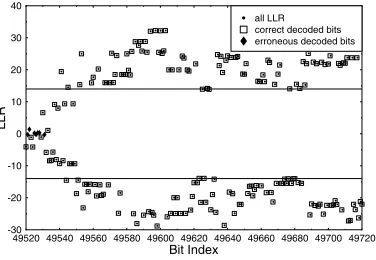
In Figure 5 the LLR values are plotted for 200 bits against the bit-index taken from a random sample. The entire sample has a total of 165x13000x(1-0.1)=1930500 bits based on Table I. The circles denote the correctly decoded bits, while the crosses denote the erroneously decoded bits. Note that most of the bits that are located outside the threshold region represented by the horizontal lines are indeed likely to be error-free, since at the BER of2x10−4on average a 20000 bit
segment would have a single error. By contrast, all the corrupted bits tend to be inside the threshold region, even though some LLR values within the same region may also yield correct bits.
49520 49540 49560 49580 49600 49620 49640 49660 49680 49700 49720
Bit Index
-30 -20 -10 0 10 20 30 40
LLR
... . . . .
... .
. .
. .
. .
. .
.. .
.
..
. .
... ..
. . .
. ..
..
. . .
.. .
. . ...
. ..
.
. .
. ...
. . .
. .
.. .
. . . ..
.
. .
. .
. ..
.
. ..
. ..
.. . .
.. . .
. . ..
.. .
. . ...
. ..
. .
. . ..
.. ...
... ..
. ..
. ..
. . .
. ..
... .
... .
. .
. . . ..
.. .
. .
.. .
. .
. ..
.... ..
. ...
.. .
.. .
...
[image:3.612.99.287.212.342.2].
all LLR correct decoded bits erroneous decoded bitsFig. 5. A set of 200 LLR values recorded for the system detailed in Table
I, given the threshold value of Figure 4 atEb/N0= 5.5dB.
Since we require a BER between10−3to10−4in order to obtain a confident LLR based packet-reliability decision we observe in Figure 3 that the BER of 3x10⁻⁴satisfies this requirement atI
A≈0.92. This may also be associated withEb/N0>5.0dB for four or more
iterations.
IV. LT DECODINGSCHEME
A. Bit-by-bit LT Decoding
It is widely recognized that LT packet decoding is sensitive to error propagation. Since it was originally designed for the BEC channel, the BER of the AWGN-contaminated packets may be mitigated by the BICM-ID decoder. An unsuccessfully decoded BICM-ID symbol is likely to cause the error propagation to other LT packets. If the
BEC’s erasure probabilityPeis high and the number of redundant
LT packets is insufficient, the LT packet decoding operation will be curtailed. This problem can be mitigated by using bit-by-bit LT decoding. With the intrinsically inherited LLR estimation, our detection of corrupted bits can be implemented directly on this new bit-by-bit scheme. The disadvantage is the increase in decoding complexity which is proportional to the number of bits in a packet.
LT Source Packets
LT Encoded
Packets 1 2 3 4 5 12 3 4 5 12 3 45 1 23 4 5 1 2 3 45 ID=1 ID=2 ID=3 ID=4 ID=5
(a) Packet−bassed LT Decoding LT Source
Packets
LT Encoded
Packets 1 2 3 4 5 12 3 4 5 12 3 45 1 23 4 5 1 2 3 45 ID=1 ID=2 ID=3 ID=4 ID=5
[image:3.612.72.309.610.712.2](b) Bit−by−bit LT Decoding
Fig. 6. Packet-based LT decoding and bit-by-bit LT decoding.
Figure 6 illustrates (a) our packet-based LT-decoding and (b) bit-by-bit LT-decoding strategies. The corrupted bits of the packets are shown as filled rectangles in the figure.
When using bit-by-bit decoding, the corrupted bits can be identified with the aid of LLR estimation and this enables us to use the rest of the reliable LT-encoded bits and hence to continue the LT decoding process.
B. Pseudo Random LT Generator Matrix
The design of LT codes critically depends on their so-called degree distribution [8]. It was also stated in [4], [9] that the specific degree distribution of LT codes has a strong influence on the percentage of redundant packets required for error-free detection, which is the
E-value of the buffer feedback link of Figure 1. Given a specific LT-code degree distribution, a further influential factor in determining the performance of a LT code is the particular choice of the random generator, which controls the actual assignment of the set of original source packets contributing to a specific LT encoded packets, as shown in Figure 6. Since this problem has not been addressed in the open literature, we propose a novel technique for reducing the minimum required fraction of redundant packets in the context of LT codes.
The conventional technique of generating pseudo-random integers for pin-pointing the particular original information packets to be combined with the aid of modulo-2 additions to generate a given LT-encoded packet is using finite-length Shift Registers (SR). Given
anm-stage SR, the number of possible integer numbers that may
be generated isM = (2m−1)and the next integer number I
n at the output of the SR is uniquely determined by the previous integer number (In−1) according to the function ofIn=f(In−1), which map the finite set{I}onto itself. More explicitly, the output of the SR traverses fromIn−1toInby picking any of theM= (2m−1) elements with the same probability.
As an alternative, a sequence of integer numbers may be generated by linear congruential generators which obey the following relation
Ij+1= (aIj+C)mod M, (1) whereMis the modulus, whileaandCare positive integers refered to as the multiplier and the increment respectively. The period of the shift register is not longer thanM. WhenMis close to its maximum legitimate value of(2m−1), the sequence generated becomes more correlated, i.e. loses its pseudo-random nature. As a further feature, the linear congruential generator makes the least significant bits more correlated than the most significant bits.
The random integer number generator used for LT codes in [8] [10] and [4] uses the random generator which has the length of232 equal to a 32 bits register and the process is based on the formula
In= (In−1+C)mod M (2)
We opted for using the random sequence generated from (2) for LT encoding, when choosing randomly the modulo-2 connections between the LT source packets and the LT encoded packets as illustrated in Figure 6. An example of the degree of connections between the LT source and LT-encoded packets is shown in Figure
7, corresponding to 1.06×2011 LT-encoded packets, where the
0 500 1000 1500 2000 LT Source Packet Indices
0 5 10 15 20 Degrees of L T Source Packets . . . .. . . . . . . . . . . . .. . . . . . . . . . . . . . . . . . . . . . . .. . .. . .. . . . . . . . . . . . . . . . . ... . . . . . . . . . .. . . . . . . . .. . . . . . . . . . . . . . . .. . .. . . . . . . . . . . . . . . . . . . . . . . . . . . . . . . . .. .. . . . . . . . . . . . . . . ... . .. . . . . . . . . . . . . . .. . . . . . . . . . . . . . .. . . . . .. . . ... . . . . . . . . . . . . . .. . .. . . . . . . . . . . .. . .... . .. . . . . . . . . . . . . . . . .. . .. . . . . . . . . . . . . . .. . . .. . . . . . .. . . .. . .. ... . . .. .. . . . . . . . . . .. .. .. . . . . . . . . . .. . . . . . . . . . . . . .. . . . . . . . . . . . . . . . . . . . . . . . . . . . . . . . . . . . . . . . . . . . . . . . . . . . . .. . . . . . .. . . . . . . . . . . .. .. .. . . . . . . . . . . . . . . .. . . . . .. . . . . . . . . . . . . . . . . . . .. . . . . . . . . . . .. . ... . . . . .. . . . . .. . . .. . . . . . . . .. . . . . . . . ... .. . . . . . . . . . . . . . . .. . . .. . . . . . . . . . . . ... . . . . . . . . . . . . . . . . . . . . . . . . .. . . . . . . . . . . . . . . .. . . . . . . . . . . . . . . . . . . . . . . .. . . .. . . . . . . . . . . . . . . . . . .. . . . . . . . . . . . . . . . . . . . . . . . .. . . . . . . . . . . . . . . . . . . . . . . . . .. . . . .. . . . . . . . . . . . . . . . . .. .. . . . . . . . . . . . . . . . . . . . . . . . . . .. . . . . . . . . . . . . . . . . . . . . . . . . . .. . . . . . . . . . . . . . . . . . . . . . .. . . . . . . . . . . . . . . . . . .. . . . . . . . . . . . . . . . . . . . . . . . .. . . . . . . . . . . . . . .. . . .. . . .. . . . . . . . . . . .. . . . . . . . . . . . . . . . . . . . . ... .. . . . . . . . . . . . . . . . . . . . . . . . .. . . . .. . . .. . .. . . . . . . . . . . . ... . . . . . . . . . . . . . . . . . . . . . . .. . . . . . . . . . . . . . . . .. . . . . . . . . . . . . ... . . . . . .. . . . . . . .. . . . . . . . . . . . . . . . . . .. . . . . . . . . . . . . .. . . . . . . . . . . . . . . . . . . . . . .. . . . . . . . . . . .. . . . .. . . . .. . .. . . . . . . .. . . . . . . . .. . . . . . . . . . . . .. . . . . . . . . . . . . . . . . . . . . . . . . . . .. . . .. . . . . . . .. . . . . .. .. ... .. .. .. . .. . . .. . . . .. . . . .. . . . . .. . . . . . . . . . . . . . . . . . . . . . . . . . . .. . . . .. . .. . . . ... .. . . . . . . . . . . . . . . . . . . . . . . . . . . . . . .. .. . . . . . .. . . . .. . . . . ... . ... . . . . . . . . . . . . . . . . . .. . . . . .. . . . . . . . . . . . .. . . . . . . . . . . . . . . . . . . . . . . . . .. . . . . . . . . . . .. . . . . . . .. . . .. .. . .. . . . . . . . . . . . . . . . . ... . . .. .. . . . . . .. . . . .. . . . . . . . . . . . . . . . . . . . . .. . . . .. . . . . . . . . .. . . . . . .. . . . . . . .. . . . . .. . . . . . .. . . . . . . . . . . .. . . . . . . ... . . . . . .. . . . . . . . . . . . . . . . .... . . . . . . . . . . . . . . . . . . .... . . . ... . .. . . . . .. . . . . . . . . . .. . . . . . . . .. . . . . . .. . . . . . . . . . . . . . . .. . . .. . . . . . . .. . . . . . . . . . . . . .. .. . .. . . . . . . ... . . . .. . . . . . . . . . . . . . . . .. . . . .. . . . . . . . . . . . . . . .... . . . . . . . . . . . . . . . . . . .. . . . . . . . . .. .. . . . . . ... .. . . . . . .. . . . . . . . . . . . . . . . . . . ... . . . . . .. .. . . . . . . . . . . . . . . . . . . . . . . . . . .. . . . . .. .. .. .. . . . . . . . . . ... . . . . . . . . . .. . . . .. . ... . . .. . . . . . . . . . . . . . . . . . .. . . . . . .. . . . .. . . . . . . . . . . . . . . . . . . . .. . . .. . . . . . . . . . . . . . . . . . . . . . . . . . . . . . . . . . . .. . . . . . . .. . . . . . . . . . .. . . . . . . . . .. . . . . . . . .. . . . . . . . . . . . . .
Fig. 7. A snapshot of the integer random numbers generated by the
congruential generator of (2) forM= 32.
overhead of the LT encoded packets. For the sake of avoiding this, we introduce a solution for designing a better random integer number generator of LT codes.
For the sake of generating an uncorrelated set of integer numbers we apply the random generator relying on rearranging the bits of a shift register proposed in [3] [11]. We introduce two different types of random rotation generators. The first method suggests that the bits are rotated after their modulo 2 addition
In= ((In−j+In−k)mod2b)rot r. (3)
By contrast, the second method proposes that the bits are rear-ranged before their modulo 2 addition
In= ((In−j rot r1) + (In−krot r2))mod2b, (4)
where In is an integer presented by b bits and the notation
In−j(rot)r1means that the bits ofIn−jare shifted to the right byr1
positions, for example according to000011112(rot)3 = 111000012.
When using the pseudo-random integer number generator of (4), the LT code achieves a better performance than using the traditional linear congruential pseudo-random integer number generators of (2) although these results are not included here owing to lack of space. Fig. 8 shows the evolution of the degree of connections for the LT source packet indices after encoding 1.06x2011 number of LT encoded packets using the pseudo-random integer number generator of (4), where in contrast to Figure 7 no degree-zero connections are found, which can cause potential decoder failures.
0 500 1000 1500 2000
LT Source Packet Indices 0 5 10 15 20 Degrees of L T Source Packets . . .. . . .. . . . . . . . . . .. . ... .. . . .. . . . . .... . . . . . . . .. . . . . . . . . . . .. . .. . . . . . . . . . . . . . . . . . . .. . . . . . . . . . . . . . . .. . .. . . . . . . . . . . . .. . . . .. .. . . . . . . . . .. . . . . . . . . . . . . . . . . . . . . . .. .. . . .. . . . . . . . . . . . . . . . . . . . . . .. . . . . . . .. . .. .... . . . .. . . . . . . . . . . . . . . . . .. . . . .. . . . . . . . . .. . .. . . .. . . . . . . . . . . . . . . . . . . . . . . . .. . . . . . . ... . . .. . . . . . . . . . . . . . . . . . ... . . . . .. . . . . . . . . . . . . . . . . . . . . . . . . . . . . .. . . . . . . . . . . . . . . . . . . . . . . .. . . . . . . . .. . . . . . . . .. .. . . . . .. . .. . . . . . . . . . . . . . . . . . . . . . . . . . . . . . . . . . .. . . . .. . . . . . . . .. . . . . . . . . .. . . . . . . .. . . . ... . . . . . . . . .. . . ... . . . . . . . . . . .. . . ... . . .. .. . . . . . . . . . . .. . . . . . . . .. .. . . . ... . . . . .. . . . . ... . . . . . . . . .. . . . . . . . . . . . . . . . . . . . . . . . . .. . . . .. . . . . . . . . . . . . . . . . . . . . .. . .. . . . . . . . . . . . . . . . . .. . .. . . . . . . . . . .. . . . . . . . . . . . . . . . . . . . . . . . .. . . . . . . .. . . . . . . . . . .. . . . .. . . . . . . . .. . . . .. . . . . . . .. . . . . . . . . . .. . .. . . . . . . . . . . . .. . . . .. . . . . . . . .. .. . . . . . . . . . . . . . . .. ... . . . . .. . . . .. . . .. . . . . . . . . . . . . . . . . . .. . . . . . . . . . . . .. . . . . . . . . . . . . . . . . . . . . .. . . . . . . . . . . .. . . . . . . . . . . . . . . . . . . .. . . . . . . . . . .. . . . . . . . . . . . . .. . . . . . . . . . .. .. . . . . . . . . . . . .. . . . . . . . . . . . . . . . . . .. . .. .. . . . . . . . . . .. . . . . . . . .. . .. . . . . . . . . . ... . . . .. . . . . . . . . . . . . . . . . . . .. . . . . . . . . . . . . . . . . . . . ... . . . . . . . .. .. . . . . . . ... . . . . . . . . . . . . .. . . . . . . . . . . . . . . . . . . . . . . . . . . . . . . . . . . . . . . . .. . . . .. . . . ... . .. . . . . . . . ... . . . . . .. . . .. . . . . . .. . . . . . .. . . . . . . . . .. . . . . . . . .. . . .. . . . . . . . . . . . . . . . . .. .. . . .. . . . . . . . . . . . . . . . . . . . . . . . .. . . . .. . . . .. . . . .. . . . . . . .... . . . . . . . . . . . . ... . . . . . . . . . . . . . . . . . . .... . . . . .. . . . . . . . . . . . . . . . . . . . . . . . . .. . . . . .. . . . . . . . . . . . . . . . . . . . . .. .. . . . . . . . . .. ... . . . . . . . .. . . . . .. . . . .. . . . . . . .. . . . . . . . . . . . . . . . . . . .... . . . . . . . . .. . . . ... . . . . . . . . . . . . ... . . . . . . . .. . . . . . .. . . . . . . . . . . . . . . . . . . . . . . . . . . . . . .. . . . .. . . . . . . .. .. . . . . . . . . . . . . . .. . . . . . . . . .. . . . . . . . . . . . . . . . . . . . . .. . . . .. . . . .. . . . . . . . . . .. . . . . . . . . . .. . . . . .. . . . . .. ... . . . ... . . . . . . . . . ... . . . . . . . . .. . . . . . . . ... ... . . . . . . .. . . . .. . . . . . . . . ... . . . . . . . . . . . .. . .. . . . . . . . . . . . . . .. . . . . . . . . . . . . ... . . . . . . . . . . . . . . . . .. ... . .. . .. . . . . . . . . . . . .. . . . . . . . . . . .. . . . . . . . . . . . . . . . . . . . . .. . . . . . . . . . .. . . .... . . . . . . . . . . . . . . . . . . . ... . . . . . . .. . .. . . .. . . . . . . . . . . . . . . . .. . .. . .. . . . . .. . . . . . . . . . . . . ... . . . . . . . . . . .. . . . . . . . . . . . . . . . . . .. .. . .. . .. . . . . . . . . . . . . . . .. . . . . . . . . .. . . . . . . . . . . . . . . . ... . . . . . .. . . . . . . . . . . .. .. . . . . . . . . . . .. . . . . . . .
Fig. 8. A snapshot of the integer random numbers generated by the pseudo-random generator of (4).
We further investigate the benefits of the specific pseudo-random generator of (4) by comparing the normalised number of packets required for successful LT decoding. The parameters of the specific LT degree of distribution used in the simulations arec=0.1,δ=0.5 [4] and the required number of LT encoded packets is normalized by the
number of LT source packetsK. From Figure 9 and Figure 10 we
observe that the number of LT encoded packets required in Figure 9 is smaller than in Figure 10. More specifically, the required number
of LT encoded packets only varies in the range spanning from 1.06 to 1.085 in Figure 9, while it varies from 1.06 to 1.10 in Figure 10.
1.0 1.021.04 1.06 1.08 1.1 1.12 1.14 1.16 1.18 1.2 Nomalized number of required packets 0.0 0.05 0.1 0.15 0.2 0.25 0.3 0.35 0.4 Probability of recovering the source file
Fig. 9. The degree histogram of the LT code using the pseudo-random integer number generator of (4).
1.0 1.021.04 1.06 1.08 1.1 1.12 1.14 1.16 1.18 1.2 Nomalized number of required packets 0.0 0.05 0.1 0.15 0.2 0.25 0.3 0.35 0.4 Probability of recovering the source file
Fig. 10. The degree histogram of the LT code using the linear congruential
pseudo-random integer number generator of (2).
V. SIMULATIONRESULTS
In this section we embark on quantifying the simulation results for our proposed joint scheme. The system parameters employed in our simulation results are shown in Table I.
When encoding the same number of source packets K=2011,
Figure 11 shows the BER versus the normalized number of LT-encoded packets using both the pseudo-random and congruential pseudo-random integer number generators of (2) and (4). It can be seen from Figure 11 that the random generator of (4) reduces the total number of LT-encoded packets compared to that of (2) by 3% at BER=10−5.
1.04 1.05 1.06 1.07 1.08 1.09 1.1 1.11 1.12 1.13 1.14 1.15 Normalized No. of Packets
10-5 10-4 10-3 10-2 10-1 1 BER
1.04 1.05 1.06 1.07 1.08 1.09 1.1 1.11 1.12 1.13 1.14 1.15
Normalized No. of Packets
10-5 10-4 10-3 10-2 10-1 1 BER
LT(2011,c=0.1,delta=0.5) : linear congruential LT(2011,c=0.1,delta=0.5) : reordering-based
Fig. 11. BER versus the number of LT-encoded packets when transmitting
2011 packets over a BEC havingPe= 0.1and contaminated by AWGN in
conjunction with the system parameters of Table I and usingc=0.1,δ=0.5.
5 6 7 8 9 Eb/N0(dB)
10-5
10-4 10-3 10-2
10-1 1
BER
5 6 7 8 9
Eb/N0(dB) 10-5
10-4 10-3 10-2 10-1 1
BER
LT-BICM-ID 1-iter LT-BICM-ID 2-iter LT-BICM-ID 10-iter
Fig. 12. BER versusEb/N0performance, when communicating over a BEC
channel havingPe= 0.1and contaminated by AWGN, when using thedegree
distribution of (4).
5 6 7 8 9
Eb/N0(dB) 10-5
10-4 10-3
10-2 10-1
1
BER
5 6 7 8 9
Eb/N0(dB) 10-5
10-4 10-3 10-2 10-1 1
BER
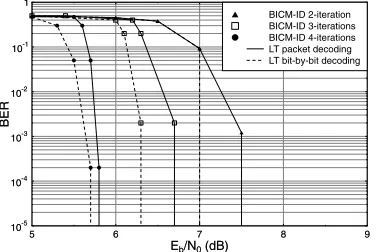
[image:5.612.98.285.51.179.2]BICM-ID 2-iteration BICM-ID 3-iterations BICM-ID 4-iterations LT packet decoding LT bit-by-bit decoding
Fig. 13. BER versusEb/N0 performance, when communicating over a
BEC channel havingPe= 0.1contaminated by AWGN using perfect CRC
estimation as well as the parameters of Table I.
decoder. An infinitesimally low BER is achieved forEb/N0 values
in excess of 7.4dB.
When using an exchange of soft information between the LLR buffer and LT decoder of Figure 1, Figure 14 shows the significant performance improvement achieved by the system. Figures 13 and 14 include the results recorded for both the LT packet decoding as well as for the LT bit-by-bit decoding methods.
5 6 7 8 9
Eb/N0(dB) 10-5
10-4 10-3
10-2 10-1
1
BER
5 6 7 8 9
Eb/N0(dB) 10-5
10-4 10-3 10-2 10-1 1
BER
BICM-ID 2-iteration BICM-ID 3-iterations BICM-ID 4-iterations LT packet decoding LT bit-by-bit decoding
Fig. 14. BER versusEb/N0 performance, when communicating over a
BEC channel having Pe = 0.1and contaminated by AWGN using LLR
based reliability estimation and the parameters of Table I.
Finally, in Figure 15 we compare the bit-rearrangement based pseudo random generator of (4) and the traditional congruent random generator of (2) for specifying the modulo-2 connections between the LT source packets and the LT-encoded packets. The technique of (4) is capable of reducing the number of source packets required for achieving infinitesimally low BER. More explicitly, Figure 15 shows
the improved BER performance recorded, when usingK= 11 000
packets instead of the originally statedK=13 000 packets specified in Table I. This is achieved when the available redundant packets have been limited by the source input.
5 6 7 8 9
Eb/N0(dB) 10-5
10-4
10-3 10-2
10-1 1
BER
5 6 7 8 9
Eb/N0(dB) 10-5
10-4 10-3 10-2 10-1 1
BER
BICM-ID 2-iteration BICM-ID 3-iterations BICM-ID 4-iterations Congruential Random Generator Bit Swapping Random Generator
Fig. 15. BER versusEb/N0performance when communicating over a BEC
channel having Pe = 0.1and contaminated by AWGN using LLR based
reliability estimation and the parameters of Table I. The number of source
packets was reduced toK= 11 000fromK= 13 000.
VI. CONCLUSIONS
A jointly designed BICM-ID and LT coding scheme was proposed for mitigating the effects of the AWGN-contaminated BEC. The novel features of the scheme included:
1) a bit-by-bit LT decoder;
2) an LLR-based reliability estimator for the sake of avoiding the classic CRC overhead;
3) a bit-rearrangement based random generator, which resulted in an improved LT-generator, which is capable of reducing the LT-encoded packet overhead required for maintaining an infinitesimally low BER.
REFERENCES
[1] J. Buyers, M. Luby and M. Mitzenmacher, “A Digital Fountain Approach
to Asynchronous Reliable Multicast,”IEEE Journal on Selected Areas
in Communications, vol. 20, pp. 1528–1540, October 2002.
[2] E. Zehavi, “8-PSK Trellis Codes for a Rayleigh Fading Channel,”IEEE
Transactions on Communications, vol. 40, pp. 873–883, May 1992. [3] M. Matsumoto and T. Nishimura, “A 623-Dimensionally Equidistributed
Uniform Pseudo-Random Number Generator,” ACM Transactions on
Modeling and Computer Simulation, vol. 8, pp. 31–42, 1998. [4] R. Y. S. Tee, T. D. Nguyen, L. L. Yang and L. Hanzo, “Serially
Concatenated Luby Transform Coding and Bit-Interleaved Coded
Mod-ulation Using Iteratlive Decoding for the Wireless Internet,” inVehicular
Technology Conference, vol. 5, (Melbourne, Austrialia), pp. 2494–2498, Spring 2006.
[5] T.D. Nguyen. F.C. Kuo, L-L. Yang, L. Hanzo: Amalgamated Generalized Low Density Parity Check and Luby Transform Codes for the Wireless
Internet, Proceedings of IEEE VTC’07 Spring, April, 2007, Dublin,
Ireland, pp 2440 - 2444
[6] Q. Luo and P. Sweeney, “Hybrid-ARQ Protocols Based on Multilevel
Coded Modulation,”IEE Electronics Letters, vol. 39, pp. 1063 – 1065,
July 2003.
[7] T. Clevorn, S. Godtmann and P. Vary, “BER Prediction Using EXIT
Charts For BICM With Iterative Decoding,” IEEE Communications
Letters, vol. 10, pp. 49–51, January 2006.
[8] M. Luby, “LT codes,” inProceeding of the 43rd Annual IEEE
Sym-posium on Foundations of Computer Science, pp. 271–282, November 2002.
[9] D. J. C. MacKay,Fountain Codes. http://www.inference.phy.cam.ac.uk/
mackay/CodesTheory.html: Cavendish Laboratory, University of Cam-bridge, 2004.
[10] D. J. C. MacKay,Information Theory, Interference and Learning
Al-gorithms. http://www.inference.phy.cam.ac.uk/mackay/itila/: Cambridge University Press, 2003.
[11] A. Fog, Chaotic Random Number Generators with Random Cycle
[image:5.612.341.529.95.226.2] [image:5.612.96.285.221.349.2] [image:5.612.96.284.485.611.2]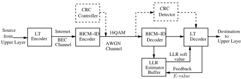
![Figure 2 shows the basic BICM-ID scheme, where = f(IADecDataExtDecADec. Usingthe technique proposed in [7] we are capable of plotting both theEXIT chart and the corresponding BER values are plotted in Figure 3assuming that the variance of the Gaussian dist](https://thumb-us.123doks.com/thumbv2/123dok_us/8497289.346404/2.612.338.529.512.623/iadecdataextdecadec-usingthe-technique-plotting-corresponding-assuming-variance-gaussian.webp)