ICTA’07, April 12-14, Hammamet, Tunisia
An Arabic Optical Braille Recognition System
AbdulMalik Al-Salman, Yosef AlOhali, Mohammed AlKanhal, and Abdullah AlRajih
King Saud University and KACST, Riyadh, Saudi Arabia
Abstract
Technology has shown great promise in providing access to textual information for visually impaired people. Optical Braille Recognition (OBR) allows people with visual impairments to read volumes of typewritten documents with the help of flatbed scanners and OBR software. This project looks at developing a system to recognize an image of embossed Arabic Braille and then convert it to text. It particularly aims to build fully functional Optical Arabic Braille Recognition system. It has two main tasks, first is to recognize printed Braille cells, and second is to convert them to regular text. Converting Braille to text is not simply a one to one mapping, because one cell may represent one symbol (alphabet letter, digit, or special character), two or more symbols, or part of a symbol. Moreover, multiple cells may represent a single symbol.
1. Introduction
Visually impaired people are part of the society, and can play an integral role in its prosperity. Therefore, it has been a must to provide those people with means and systems through which they may communicate with the world. These systems should depend on the sense of hearing or touching. Many systems have been developed to achieve this purpose; the most famous system that is based on touching is Braille system. Braille is a writing system that enables visually people to read and write through touch using a series of raised dots to be read with their fingers.
Braille contractions representing groups of letters or whole words that appear frequently in a language. This is usually referred to as Grade 2 Braille. The use of contractions permits faster Braille reading and helps reduce the size of Braille books, making them somewhat less cumbersome. Each Braille character or "cell" is made of 6 dots arranged in a rectangle comprising 2 columns of 3 dots each as it can be seen in Figure 1. A dot may be raised at any of the 6
positions, or any combination. Counting the space, in which no dot is raised, there are 64 such combinations (that is 26 = 64).
The dimensions of a Braille dot have been set according to the tactile resolution of the fingertips of person. The horizontal and vertical distance between dots in a character, the distance between cells representing a word and the inter-line distance are also specified by
the Library of Congress. Dot height is approximately 0.02 inches (0.5 mm); the horizontal and vertical spacing between dot centers within a Braille cell is approximately 0.1 inches (2.5 mm); the blank space between dots on adjacent cells is approximately 0.15 inches (3.75 mm) horizontally and 0.2 inches (5.0 mm) vertically. A standard Braille page is 11 inches by 11.5 inches and typically has a maximum of 40 to 43 Braille cells per line and 25 lines. Braille has been adapted to write many different languages including Arabic and is also used for musical and mathematical notation. Note that both Arabic and English Braille are read from left-to-right.
For OBR, a Braille document is placed on a standard scanner and scanned by the OBR program, which either converts the document into text or saves it as a formatted Braille file. OBR works with single-side or double-sided Braille using a single scan.
OBR offers many benefits to Braille users and those who work with them, facilitating communication, reducing storage space, and preserving out-of-print Braille texts. Everyone who works with blind people and does not read Braille will benefit from using the OBR. For example: parents, teachers, public organizations communicating with blind individuals, and computerized Braille libraries. All people in workplaces where Braille is used can read Braille easily by using an OBR.
This paper looks at developing algorithms to recognize an image of embossed Arabic Braille
material obtained by a regular scanner. Although the Braille dots have the same color as the background, they cast soft shadows when scanned with a standard flatbed scanner. These shadows are used to locate the dots on the page. As the dots on both sides of the page are visible from one side, both sides of the page can be recognized in a single scan. The recognition engine is capable of processing Braille documents with various paper colors, number of dots, Braille cell sizes, and orientations. To convert the Braille cells to text, a translation engine is needed
2. Literature Review
An OBR system consists of several basic modules including: image acquisition, image processing, dot localization and segmentation, and finally dot recognition and conversion. Among issues that must be taken into consideration when implementing an OBR system are factors that negatively influence the identification process, such as lighting conditions, page placement in the scanner, and page movement [6].
Image acquisition is the first and most important step in any pattern recognition system. In OBR systems data is provided to the system in the form of images of Braille embossed pages. The process of acquiring these images digitally can be achieved by using a number of different equipments such as scanners or digital cameras, both of which have been used by developers and researchers [2-4, 7, 9-12].
Image preprocessing is an essential step during which errors that occurred while the images were taken are eliminated. Errors include noise, deformation, bad illumination or blurring. Image preprocessing can be used for image enhancement by reducing noise, sharpening images, or rotating a skewed page. The algorithms used differ from one system to another depending on the classification approach followed by researchers and developers.
An early effort was presented by Mennens et al. in their work [4]. The authors addressed the problem of false shadows in the image caused by the fact that Braille pages are never perfectly flat due to the tension in the paper’s surface, by subtracting a locally averaged image from the original. The authors rotate skewed images by using the deviation over a vertical projection of the image.
Hermida’s et al. [3] system employed thresholding before the image is passed on to the Braille dot extraction module. Their algorithm converts a digital image of a scanned Braille page into one consisting mainly of black and white spots denoting the dots. The
thresholds used were adaptively calculated from the histogram of the input image.
In 1995, Hentzschel and Blenkhorn [2] presented a system for optical Braille recognition based on twin shadows approach, which subtracts two images of the same Braille page, where each image was taken under different illumination conditions. This helps eliminate blemish and noise in images caused by the texture of the paper used. Unlike Blenkhorn’s work [1] presented in 1994 that solely discussed the classification process, his work in association with Hentzschel in the following year addressed the different modules of a pattern recognition system, including image processing. In [2], the image-processing module encompassed a variety of routines, each serving a different and crucial purpose as using random-noise reduction filter that was necessary to avoid undesired emphasis of noise.
In [8], preprocessing consists of two sub-operations: noise filtering and edge enhancement. Noise filtering is achieved via a low-pass special Gaussian filter. Edge detection is achieved using convolution Sobel kernels.
The approach adopted by Mennens et al. in [4] for extracting Braille dots is based on several assumptions, one of which is that a single dot is represented by two gray level intensities, a light area right above a dark one. Also their system is designed to recognize a double-sided Braille page. This approach may produce false core regions if two dots are vertically neighbors.
The localization and extraction algorithm developed by Hermida et al. [3] takes a thresholded image consisting of couples of white and black spots, where each couple denotes a single Braille dot. Though this method is easy and quick, it suffers from that: if some legitimate points are lost, false ones are produced.
The dot localization and extraction technique used in [2] consists of two steps; the first is image registration and the second is character segmentation. The final step of dot extraction is normalization, where each Braille character is represented by a 2x3 matrix. Each bit in the matrix denotes a dot in Braille cell. Deciding whether a bit value is either 0 or 1 is based on a threshold used to test 1/6 of the cell area.
In 2004, Wong et al. [7] proposed an OBR system that is capable of recognizing a single sided Braille page in addition to preserving the format of the original document in the produced text file. The algorithm processes the image one row at a time reducing the computation time significantly.
was possible due to the difference in light reflectance between recto and verso dots. A hardware circuit configuration that corresponds to the equations and operates in a similar manner was given as well.
Mennens et al. [4] adopted Binary Braille cell sets as basis for their classifier, which is grouping the dots and representing each dot by a bit position. The authors did not elaborate on the comparison method used to recognize a Braille cell as a certain letter or digit. The classifier presented by Hermida et al [3] takes as an input the image produced from the dot extraction module, where characters are represented as a group of dots, each dot is in turn represented by a single bit, with 1 or 0 values. Using this representation, the Braille-to-ASCII conversion is accomplished.
The system proposed in [1] is based on finite state approach that operates with a finite number of states that perceives the correct state, in addition to its ability to perform both left and right context checking using matching algorithms. This feature is very important in determining characters proceeding wildcards. One of the greatest advantages of this system is that it is designed in a way to perform the conversion from Braille to any of the natural languages depending on the tables provided containing the conversion rules.
The work in [2] did not elaborate on the techniques used for converting an extracted Braille cell into natural language characters.
The recognition module in [7] is designed to work with thresholded images resulting from the half-character detection module. The classification process is carried out using a probabilistic neural network.
For interpretation purposes, authors in [8] determine centriod distances between each dot and its four possible neighbors. Dots are then grouped into cells. Based on the boundary coordinates, information and illumination characteristics, two standard templates were then constructed to represent the front-face dots and back-front-face dots.
To the best of our knowledge, there is only one commercial OBR software. It is a Windows-based software that allows reading single and double-sided Braille documents with a standard scanner [13]. Unfortunately, it does not support the Arabic language and there is no explanation of the used techniques.
3. The Arabic OBR System
The Arabic OBR system is able to recognize both single-sided and double-sided Arabic Braille documents from a single scan. It comprises the following stages. First, an image of a Braille document page is obtained using a flatbed scanner. Second, the
image is converted to a gray color. Following that any white or black frames are cropped. The image is then thresholded so that only three classes of regions exist: dark, light and background. In case of having a tilted paper then de-skewing is applied using a binary search algorithm. Having labeled each of the different types of regions, an initial identification of Braille dots is performed. Finally, Braille cells are then recognized. Each stage is described below in more detail.
3.1 Converting the Image to Gray Level
Inside a computer system, colored images are stored in 3-D arrays while gray level images are stored in 2-D
arrays. Dealing with 2-D arrays is much easier and faster. Therefore, the first step in the proposed system converts colored scanned images to gray level so that any pixel value in the image falls within the range 0-255 as could be seen in Figures 2 and 3.
3.2 Cropping the Image Frame
Some of the scanned images suffer from having either black or white frames that would affect the thresholding step coming next. It is a must that those frames are cropped before proceeding forward. To do that, the average gray level is calculated for the whole image and then for each of the rows and columns separately. Finding a row or column average gray level that is above or below 15% of the whole image average gray level is an indication to delete it as experiences have shown.
3.3 Image Thresholding
[image:3.595.309.529.264.381.2]This step involves examining each pixel in the 2-D array representing the scanned Braille document and classifying it to one of the following three categories: (1) Elements having values 32 and above are considered bright and given a threshold value +1. (2) Elements having values 23 and below are considered dark and given a threshold value -1. (3) Elements having values between 23 and 32 are considered gray and given a threshold value 0.
Figure 2. An example of a part of a colored scanned Braille document
An algorithm was developed to handle the thresholding. This algorithm works as follows; after converting the image to gray level and removing highest and lowest values to leave out distinct values, the average gray level for the whole image is calculated. After that both a and b values are calculated according to the following equations:
a = mean ( max(I) + avg ) / 2 b = mean ( min(I) + avg ) / 2;
Where I is an array representing the whole image, max(I) and min(I) represent the highest and lowest values respectively in each column of the array I.
The classification parameters L and H are calculated according to the following equations:
L = avg – ( avg – min_avg ) / 3 H = avg + ( max_avg – avg ) /3;
Where min_avg
represents the average of all values less than b
while max_avg
represents the average of all values higher than a. The image is then classified according to L and H values (see Figure 4). Values less than L are considered dark. Values higher than H are considered bright. Values between L and H are considered gray (background).
Having noticed that the histogram of a scanned Braille document is represented by the Gaussian Distribution, we
found that 1.5*σ, where σ is the standard
deviation, gives good results when finding L and H values. Image pixel values above H are
bright and those blow L are dark (m is the man). See Figure 5.
3.4 Image De-Skewing
We have developed a binary search algorithm to correct any de-skewing in tilted scanned images. The maximum degree of recognizing a de-skewed image is 4 degrees from either the left or the right side. To calculate the de-skewing degree we have used the following algorithm:
1. After thresholding the image (stage 3) we select either the dark or the bright part that resulted from thresholding and delete the other part.
2. Horizontal projection is performed to count the number of pixels in each row for the selected part in the previous step. Then we calculate those rows having more than 10 points.
3. The image is rotated 4 degrees one time to the left and one to the right and in each time step (2) is repeated.
4. Calculating the number of rows in the image in its three case (right/ left/ middle) we have either of the two possibilities: (a) if the number of rows for the right and left side is the same then the image is not skewed and we stop here (b) if the number of the rows for the right and left side is different then the image is skewed and we proceed to step 5.
5. At this step we have two possibilities as well: (a) if the number of rows in the right side is less than that for the left side then we set the middle point calculated in the fourth step to be the new starting point for the left side. We then calculate the number of rows for this new middle point for both the right and left sides, (b) if the number of rows in the left side is less than that for the right side then we set the middle point calculated in the fourth step to be the new starting point for the right side. We then calculate the number of rows for this new middle point for both the right and left sides. 6. Repeat steps 4 and 5 as long as half the difference
between the right and left deviation is more than 1/16.
After determining the deviation degree, we rotate the original gray image and then repeat steps 2 and 3 for the rotated image. This is done because if the image is skewed then cropping may remove
some of the image parts that constitute Braille cells as could be seen in Figure 6.
3.5 Dot Parts Detection
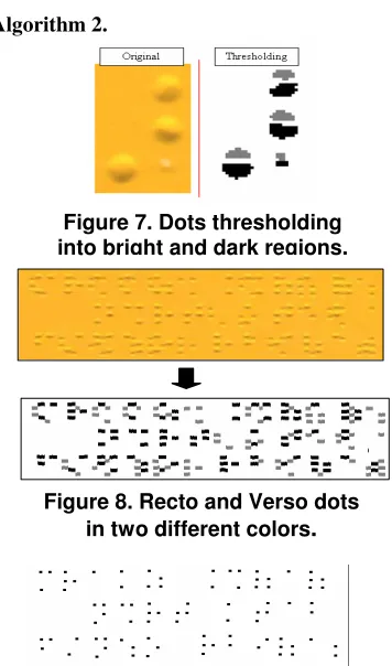
Experiences have shown that detection of Braille dot parts is better than detection of the whole dot. It was also proven that the average dot height is 8 pixels. Each dot is composed of a bright and a dark region with a small space between them. See Figure 7. The implication is that if the bright region comes at top where the dark one comes at bottom then this is a recto dot, the contrary situation results in a verso dot. The Figure 5. L, H and m values
Figure 4. Image values
algorithm for dot part detection has the following steps:
1. Since the average dot height is 8 pixels and each dot is composed of a dark and a bright region with a space in between, we will look for any 8 pixels high column. For each column we are interested only in the first and second values from top and bottom.
2. Construct an empty array to hold the points. 3. As indicated before, the value assigned to bright
pixels is +1 and to dark pixels is -1, otherwise 0. 4. A vertical search for dot parts is performed on the
array starting from top to bottom such that:
• If pixel(1)+pixel(2)>0 AND pixel(7)+pixel(8) <0 then this column is part of a recto dot.
• If pixel(1)+pixel(2)<0 AND pixel(7)+pixel(8) >0 then this column is part of a verso dot.
5. In case of having any of the two conditions true we register that in the array and then go down 12 pixels since this is the vertical space between two dots.
6. At the end, we will have recto and verso dots as in Figure 8. Now we can separate them in two arrays. Errors from previous step may occur. To correct that we can use either of the following methods:
Local Measure: select the best column within all columns that are 8 pixels below it.
Global Measure: all columns are classified into three categories: columns holding recto dots, columns holding verso dots, or undefined columns.
The second method gave excellent results.
3.6 Whole Dot Detection
This stage involves the following steps:
1. A detected dot should have at least three columns, less than that is not counted in.
2. An empty array that has the same size of the one holding dots parts is constructed.
3. We perform a vertical search on the array starting from up to down, when three parts of a dot that are not more than 6 pixels apart are found then this is considered a point. This point is registered at the corresponding position in the array as 4x4 point. 4. The region holding the detected dot part in the
previous step is deleted so that it will not be considered in future searches (Detect and Clean.) Figure 9 shows the dots at the end of the search.
3.7 Braille Cells Recognition
Having identified all possible valid dots, the system defines the region containing all the dots such that no dots exist outside this region. To do this, we have to add each row and column in the array separately then
we take the first and last positive value positions. After that one of the two following algorithms can be used:
Algorithm 1.
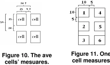
Determine the number of rows and columns in the defined region. The average line and column width have been identified as in Figure 10. To calculate the number of rows and columns we use the following two equations:
linNum = ( yMax - yMin ) / 59, colNum = ( xMax – xMin ) / 34.7;
Then we can reach the beginning of any cell by using the line and column number, as in the following equations:
i = yMin + (lin-1) * 59, j = xMin + (col-1) * 34.7;
Algorithm 2.
This algorithm does not depend on fixed lengths for cells heights and distances between them. The steps involved here are as follows:
(1) Determine the horizontal projection for the array holding the dots and then determine the average distances between the rows holding the dots.
[image:5.595.325.503.283.585.2](2) Determine the vertical projection for the array holding the dots and then determine the average distances between the columns holding the dots.
Figure 7. Dots thresholding into bright and dark regions.
Figure 8. Recto and Verso dots in two different colors
.
(3) Using the horizontal and vertical projections we can reach any cell. This is because we can consider any consecutive 3 rows and 2 columns as a cell as long as the distance between the rows and columns does not exceed the averages in (1) and (2).
By comparing the two algorithms we found that even though the latter one does not require fixed lengths to determine the cells, it is less accurate than the former one, especially that most Braille documents use the lengths and distances defined in Figure 10.
After using either of the algorithms, we now have to convert the cell to binary code. To do that, we first divide the cell into six regions as in Figure 11. Then we take each region separately, if the sum of its elements is more than 8 pixels then it will be assigned the number 1, otherwise it will be assigned 0. Then we convert the image to its decimal code representation: Decimal-Code=b1+b2*2+b3*4+b4*8+b5*16+ b6*32
The final step is to convert the decimal code to its corresponding Arabic letters to get the translation.
3.8 Correcting the Paper Layout
It might be hard for the user to recognize the correct layout of a Braille document when placed on a scanner. As a result some documents may be placed reversed by 180 degrees. To correct a reversed paper, we determine the percentage of the alphabetic in the
page. Having more than 85% indicates that the page is in its correct position while less than 45% indicates the opposite.
Horizontal and vertical reflections occur when the shadow direction is not specified in the calibration. Also, it has been shown that when the page is in its right position then the percentage of correctly recognized letters is more than the other positions.
4. Conclusion and Future Work
The proposed system has used some new techniques to recognize Braille cells using a standard scanner. The system has been tested with a wide variety of A4 scanned Braille documents, both single and double sided, written in the Arabic language and
scanned with different scanners. Overall, on single-sided and double-single-sided documents 99% of the dots are correctly recognized. The tests included different variations of Braille documents; skewed, reversed or worn-out.
We were unable to compare our work with others due to the unavailability of others as a working software, yet it gives almost similar results with the commercial OBR software (which does not support the Arabic language).
Further work will focus on Arabic/English Braille documents, large Braille papers, converting the recognized Braille cells (uncontracted and contracted, Arabic and English) to text by producing translation rules for the conversion of Braille into print for the required language, and more collaborative user interface.
5. References
[1] Blenkhorn, P., “A System for Converting Braille into Print”, IEEE transactions on rehabilitation engineering, Vol. 3, No. 2, June 1995.
[2] Hentzschel, T. W., and P. Blenkhorn, “An Optical Reading Systems for Embossed Braille Characters using a Twin Shadows Approach”, Journal of Microcomputer Applications, pp. 341-345. 1995.
[3] Hermida, X. F., et al, "A Braille O.C.R. for Blind People", Proceedings of ICSPAT-96. Boston (U.S.A.). October, 1996.
[4] Mennens, J., et al, “Optical Recognition of Braille Writing”, IEEE, 1993. pp. 428-431.
[5] Mennens, J., et al, “Optical Recognition of Braille Writing Using Standard Equipment”, IEEE transactions of rehabilitation engineering, Vol. 2, No. 4, December 1994. [6] Oyama, Y., T. Tajima, and H. Koga, “Character Recognition of Mixed Convex- Concave Braille Points and Legibility of Deteriorated Braille Points”, System and Computer in Japan, Vol. 28, No. 2, 1997.
[7] Wong, L., W. Abdulla, and S. Hussmann, “A Software Algorithm Prototype for Optical Recognition of Embossed Braille”, the 17th conference of the International Conference in Pattern Recognition, Cambridge, UK, 23-26 August 2004. [8] C. Ng and V. Lau, “Regular feature extraction for recognition of Braille”,ICCIMA'99, 1999.
[9] I. Dias, “A portable device for optically recognizing Braille-Part II: Software development”, 7th Australian & Neazlan Intelligent Information Systems Conf., pp. 18-21, Perth, W. Australia, Nov 2001.
[10] T. Gomez, et al, “AIR-Coupled Ultrasonic Scanner for Braille”, IEEE ultrasonic Symposium, pp. 591-594, 2001. [11] T. Yoshida, A. Ohya and S. Yuta, “Braille Block Detection for Autonomous Mobile Robot Navigation”, Proc. Of the 2000 IEEE/RSJ intl. Conf. on Intelligent Robots and Systems, pp. 633-638, 2000.
[12] J. Dubus, et al, “Image Processing Techniques to Perform an Autonomous System to Translate Relief Braille Figure 10. The ave
[image:6.595.78.265.427.538.2]cells’ mesuares.