This is a repository copy of
Magnetic field effects on THz quantum cascade laser: A
comparative analysis of three and four quantum well based active region design
.
White Rose Research Online URL for this paper:
http://eprints.whiterose.ac.uk/98966/
Version: Accepted Version
Article:
Daničić, A, Radovanović, J, Milanović, V et al. (2 more authors) (2016) Magnetic field
effects on THz quantum cascade laser: A comparative analysis of three and four quantum
well based active region design. Physica E: Low-Dimensional Systems and
Nanostructures, 81. pp. 275-280. ISSN 1386-9477
https://doi.org/10.1016/j.physe.2016.03.019
© 2016, Elsevier. Licensed under the Creative Commons
Attribution-NonCommercial-NoDerivatives 4.0 International
http://creativecommons.org/licenses/by-nc-nd/4.0/
[email protected] https://eprints.whiterose.ac.uk/ Reuse
Unless indicated otherwise, fulltext items are protected by copyright with all rights reserved. The copyright exception in section 29 of the Copyright, Designs and Patents Act 1988 allows the making of a single copy solely for the purpose of non-commercial research or private study within the limits of fair dealing. The publisher or other rights-holder may allow further reproduction and re-use of this version - refer to the White Rose Research Online record for this item. Where records identify the publisher as the copyright holder, users can verify any specific terms of use on the publisher’s website.
Takedown
If you consider content in White Rose Research Online to be in breach of UK law, please notify us by
Magnetic field effects on THz quantum cascade laser: a comparative
analysis of three and four quantum well based active region design
A Daničić1, J Radovanović2, V Milanović2, D Indjin3 and Z Ikonić3
1P* group, Vinča Institute of Nuclear Sciences, P.O.B. 522, University of Belgrade, 11001
Belgrade, Serbia
2School of Electrical Engineering, University of Belgrade, Bulevar kralja Aleksandra 73, 11120
Belgrade, Serbia
3Institute of Microwaves and Photonics, School of Electronic and Electrical Engineering,
University of Leeds, Woodhouse Lane, Leeds LS2 9JT, UK
E-mail: [email protected]
Abstract.We consider the influence of additional carrier confinement, achieved by application of strong
perpendicular magnetic field, on inter Landau levels electron relaxation rates and the optical gain, of two different GaAs quantum cascade laser structures operating in the terahertz spectral range. Breaking of the in-plane energy dispersion and the formation of discrete energy levels is an efficient mechanism for eventual quenching of optical phonon emission and obtaining very long electronic lifetime in the relevant laser state. We employ our detailed model for calculating the electron relaxation rates (due to interface roughness and electron–longitudinal optical phonon scattering), and solve a full set of rate equations to evaluate the carrier distribution over Landau levels. The numerical simulations are performed for three-and four-well (per period) based structures that operate at 3.9THz three-and 1.9THz, respectively, both implemented in GaAs/Al0.15Ga0.85As. Numerical results are presented for magnetic field values from 1.5 T
up to 20 T, while the band nonparabolicity is accounted for.
1. Introduction
Quantum Cascade Lasers (QCLs) have become important light sources for infrared spectroscopy within the last decade, especially when it comes to new structures operating in the terahertz (THz) region, suggesting numerous applications, such as chemical sensing, infrared imaging, non-invasive medical diagnostics and optical communications [1-13]. These devices are designed in such a manner so as to have electronic subbands defined as the upper and the lower laser level, electric pumping along the growth direction, as well as periodic repetition of active elements, which enhances the light amplification. Because of the specific properties of intersubband transitions, dynamical behavior is very different from that of inter-band lasers. The first and most important feature of intersubband transitions is very fast non-radiative scattering, proceeding on a time scale of few picoseconds [6].
THz frequencies belong to the quite under-utilized part of the electromagnetic spectrum, despite their significant application potential. This is mostly due to the lack of coherent solid-state THz sources. The so called „THz gap“ falls between two frequency ranges that have been well developed, the microwave and millimeter-wave frequency range. As the conventional semiconductor photonic devices (which are based on interband transitions) are limited to frequencies higher than those corresponding to the semiconductor energy gap, the frequency range ~1-10THz is thus inaccessible.
Terahertz QCLs are possibly the only solid-state terahertz sources that can deliver average optical power levels much greater than milliwatt that is essential for imaging applications, and also continuous wave (CW) operation for the frequency stability desired in high resolution spectroscopy techniques [5]. The realization of QCLs in the THz region was challenging because the energy of the emitted photon is comparable to the resonant energy of the longitudinal optical (LO) phonon of the host material (LO 36meV for GaAs). The physics of the intersubband transitions for such low energy spacing is still the object of active research [14].
emission frequencies throughout the 1.2− 4.9 THz range [14, 20] and with operating temperatures up to ~200 K
when operated in the pulsed mode [21]. Most recently, peak powers of larger than 1 W in pulsed mode [22] have been reported, whereas under CW operation output powers greater than 100 mW were achieved [23].
The QCL performance under the influence of a strong external magnetic field is also of special interest, as it is used to evaluate the relevant electron scattering mechanisms in the device. A detailed understanding of various scattering processes in the magnetic field assisted structures may be an important factor for improving the QCL applicability at longer wavelengths. Even though GaAs/AlGaAs QCLs are established sources in the THz range, recently, QCLs based on InGaAs/GaAsSb heterostructures have been proposed in order to improve characteristics of the devices, especially because of the conduction band offset and the low electron effective mass in this system. Their performance under the influence of a strong magnetic field has been investigated experimentally [24]. Besides aforementioned platforms, one of the options certainly is InGaAs/AlInGaAs, which turned out to be interesting choice for research, especially in the presence of external magnetic field [25], even though GaAs/AlGaAs QCLs are better option when it comes to high operating temperatures in magnetic field [25,1].Apart from investigating the physics of intersubband transitions, magnetic field operation is useful for testing new designs and/or new material combinations where lasing action is initially difficult to achieve. If the structure is functional under the magnetic field, it is an important indicator that by optimizing the fabrication process, the waveguide, etc., it can be made fully operational even without the field.
In this paper, we analyze two different QCL structures, while studying the electron relaxation rates due to electron-longitudinal optical phonon (LO phonon) scattering and interface roughness scattering (IRS), when each of the structures is subjected to a strong magnetic field parallel to the confinement direction. The best performing THz QCLs in terms of temperature employ fast electron-LO phonon scattering as a means of maintaining population inversion for achieving high output optical gain [5]. The presence of magnetic field introduces an additional quantization of the electron motion in the x-y plane (a plane perpendicular to the growth axis), by splitting the two-dimensional subbands into series of discrete Landau levels (LLs), with energies dependent on the field intensity [2]. The number of LLs of interest for given value of the magnetic field (B), as well as their exact energy values can be straightforwardly calculated, which makes the energy difference between relevant LLs pre-specified [26]. In this manner, one can affect the non-radiative scattering rates and therefore control the optical gain just by managing the magnetic field strength. By solving the full system of nonlinear rate equations, one calculates the optical gain and here we present the results of such calculations performed for two characteristic structures, lasing at 1.9THz and 3.9THz. These particular structures were chosen because they have already been fabricated and analyzed [4,5], but not in terms of output gain dependence on external magnetic field.
2. Theoretical considerations
Figure 1.Conduction band profile of a single period of THz QCL structure comprising: a) four-well design, and
b) three-well design, as described in [4,5].
The radiative transition between subbands n3 and n2 is diagonal for both structures from figure 1, The states2and2aare in resonance, enabling the fast depopulation of the lower laser state. The main scattering mechanism responsible for depopulation of the lower laser state, electron-LO phonon scattering, is described by a vertical transition. The energy difference between the states E2 and E1 is set to almost match the resonant LO-phonon energy. An additional non-radiative relaxation mechanism is taken into account, the interface roughness scattering (IRS), as it strongly affects the operation of this type of structure.
When there is no magnetic field applied, electronic subbands from figure 1 have free particle-like energy dispersion in the direction parallel to the QW planes, which may be given by:
2 2
|| 0 || 2 ||, 0
n n n n
E k E k m E ,
where m||n
En0 is the energy-dependent in-plane effective mass and k|| is the in-plane wave vector. If the whole structure is subjected to a strong magnetic fieldBin the growth direction, continuous subbands En
k|| split into series of strictly discrete states with energies:
2
22 2
, || 0 0 0 0
2
0 1 2 2 8 8 5 1 2
2
n l n
d d eB
E E k l l l l l eB
m dz dz
,
(1) where l0,1,2,...is the Landau index and
0
,
c eB m n En
is the cyclotron frequency, m being the effective mass in the well, 0 , 0 are the nonparabolicity parameters averaged over the z-coordinate, as derived in
[27]. The values ofBwhich give rise to resonant LO-phonon emission (and consequently, the dramatic reduction in the gain) are found by solving the equation: E3,0 En,l LO, where LOis the LO-phonon energy.
The LO-phonon emission rate on the transition between the initial (
i il
n
i E
E , ) and the final state (
f f l
n
f E
E , ) is given by [28]:
0 || ||
2 || 2 2 0 2 1 2 exp 2 1
4 N F q Gq dq
E E e
W i f LO q
p LO LO
E
Ei j
, (2)
where p1 denotes the difference between the reciprocal values of the static and the high-frequency dielectric constants, while stands for the width of the Gaussian distribution of the energy difference Ei Ef ,
exp 1
1
k T
Nq LO B is the mean number of LO phonons and q|| is the in-plane component of the phonon wave vector q
q||,qz
. Furthermore, F
q|| is the overlap integral defined as:
||22 22 2 || 2 2 || 2 || 2 2 ! ! 2 exp , , q L q l l q l l q
F i f
i f i l l l l l f i f
i , (3)
where eB and Lkm
x is the associated Laguerre polynomial.
*
* || '|| ' ' '
q z z
i f i f
G q
z z z z e dzdz is the suitable form factor, while i and f stand for the z-dependent parts of the wavefunctions.
In GaAs/AlGaAs QWs, monolayer fluctuations occur at the interfaces of the two materials (as the AlGaAs surface is covered by GaAs). Their influence on the carrier scattering may be described starting from the interface roughness height
r (at some in-plane position r
x,y ), and defining its correlation function as [29,30]:
' 2exp
'2 2
where
is the correlation length. After introducing the perturbation Hamiltonian '
0ˆ ,
IRS i
H U zz x y , one can calculate the scattering matrix element:
* ' *
, i, ,i xi ˆ f, ,f xf
i f n l k IRS n l k V
M
H dV . (5)Since the wavefunctions are given byn,l,kx
x,y,z
n
zl y,kx
expikxx
/ Lx , where Lx is the length ofthe structure in the x-direction, the averaged matrix element squared then reads:
2 2
2 2 2
2 ,
, exp 2 2 2
2
i f x
i f x
x F k M k L
(6)
where , , 0 *
i f
x x x i f i f
k k k F U z z
and
li lf
i f l l
2 ! !2
, while the form factor is given by:
t u
k dudtH k t H k u t H k t H u u t t k x l x l x l x l x i i i i
2 2 2 2exp 2 2 2 22
. (7)
In the above expression, Hj is the Hermite polynomial of the order j. The scattering rate could be rewritten as:
f x i x fi i f k k i f
IRS E
E E E M
W 2 exp 2 22 , , 2
. (8)
Since averaged matrix element does not depend on individual values of the wave vector components of the initial and final states, but only on their relative difference, by averaging over
i
x
k , we easily obtained:
xf i x
k
k i f M d k
L M
f x i
x
, , 22
, 2 . (9)
As IRS may appear at any surface in the structure, and roughness profiles at different interfaces are uncorrelated, we must include all the bordering surfaces, taking into account all the interface scattering along the growth axis (z axis).Now we define the total scattering rate of the system as:
i f i f i i f
LO IRS
E E E E z E E
W
W
W
. (10)In order to calculate the optical gain, one must first determine the population inversion NS3 NS2, on
which the gain depends. The electron distribution over all LLs can be found by solving the nonlinear system of rate equations, which describe the change in levels populations as a difference between the rate at which carriers arrive and the rate at which they leave the subband under consideration [31]:
f i E E i f f i E E i f f i f fi N f W
where indices i,f run over all the LLs in all the periods of the structure, while fi 1
eBNi
describes the probability that the state iis unoccupied according to the Fermi-Dirac distribution. The periodicity of the QCL design allows us to solve the system of rate equations in a simplified form, as described in [30]. Taking into account the periodic boundary conditions, each period is assumed to have an identical set of N LLs with identical electron distributions in corresponding levels. Therefore, we have N1 linearly independent equations (where N is the number of LLs in one period), and the additional one that is defined by the particle conservation law
NiNS, where NSis the total electron sheet density
.Upon determining the values of electron surface densities in all the LLs, the optical gain can be calculated (taking into account all the transitions from LLs originating from the upper laser state to LLs originating from the lower laser state), as in [30,32]:
2 2
3 2
3 2 3, 2, 3, 2,
0
2
i i i i
i
d e
g E E N N
n
, (12)where n is the refractive index of the material, and are the wavelength and the frequency of the emitted light, respectively, while Nn,l is the electron surface density in the Landau level positioned at En l, , and d32 is the transition matrix element between subbands 3 and 2.
However, in the previous expression, the influence of the magnetic field on the transition matrix element is not taken into account. As presented in [33], in the presence of magnetic field, the dipole transition matrix element can be expressed as:
0 0
2
1 * * 1 2 1 * 1
3 2 3 2
1 1
0
2 i f i f 2 i f
d B d B B l z z dzB l z dz
, (13)where
0,f0
i
and 1 ,
i f
denote the envelope wavefunctions when there is no magnetic field present and their respective first order corrections in the case of present magnetic field [33],Bis the magnetic field value andlis the Landau index. The corrections in the transition matrix element directly affect the optical gain, which can then be described with the following relation:
2 2
3 2 3 2 3, 2, 3, 2,
0
2
( ) i i i i
i
e
g d B E E N N
n
, (14)3. Numerical results
We analyzed two different GaAs/Al0.15Ga0.85As based QCL designs: four-QWs active region structure lasing at
1.9THz, and three-QWs structure lasing at 3.9THz [4, 16]. The structures exhibit a diagonal radiative transition which has proven to have a longer upper subband lifetime, leading to larger population inversion, especially at high temperatures when thermally activated LO-phonon scattering tends to diminish the population inversion. The second structure is simpler as it has one QW less per period, and also has the smallest oscillator strength of all so far known THz QCLs, while having high maximum operating temperature of ~186K [16]. As far as the four-QW structure is concerned, the layer widths are 49/78/23/76/32/76/52/168Å, starting from injector toward the collector barrier, while the electric field is set to 8.4 kV cm-1[4]. The calculated energy difference between
subbands 3 and 2 within our model is 8 meV, and the difference between the lower laser state and the ground state is 33.9meVLO. The three-QW structure has layer widths 48/85/28/85/42/164, starting from the injection barrier, with the electric field of 12.5 kV cm-1 [16].The calculated energy difference between the
subbands 3 and 2 reads 14.5 meV, while the difference between the lower laser state and the ground state amounts to 33.8 meV. The conduction band diagrams of single periods of both structures are shown in figure 1 while three adjacent periods were taken into account for calculations.
Figure 2. Landau Fan Charts. The magnetic field dependence of all relevant Landau levels for: a) four-wells
design, and b) three-wells design. In both figures, blue lines correspond to the LLs originating from the ground state of the active region, while red, green and black lines correspond to LLs originating from the lower, additional lower level and the upper laser state.
Numerical parameters used in simulations of both structures read: m* 0.0665m0, m0 being the free electron mass, Ec 0.835eV the conduction band discontinuity between GaAs and AlAs, interface roughness parameters are 1.5Å, 60Å, while the high-frequency and static permittivity are equal to 10.67 and
51 . 12
s
, respectively. The temperature is set to 77K in both cases, while the total sheet doping density is 14
10 2 . 2
S
N m-2. As described in [31,34], all the states are assumed to be broadened with Gaussian-like energy distribution that depends on the magnetic field. The electron relaxation rates due to emission on LO phonons and IRS, are calculated by using equations (2) and (8). As an illustrative quantity (to show the position of scattering resonances) we calculate the “effective” electron lifetime, inverted total scattering rate which represents a sum of the contributions of all the transition from the upper laser series (3, )i into the states originating from two lower series, showing the influence of interface roughness and LO phonon scattering.
Figure 3.The electron-interface roughness scattering rate dependence on applied magnetic field for: a) four-wells
design, and b) three-wells design.
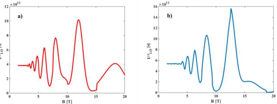
[image:7.595.65.531.480.650.2]Figure 4.The electron-LO phonon scattering rate dependence on applied magnetic field for: a) four-wells design,
and b) three-wells design.
The modal gain is calculated as:
p M
L g
G 3 2 , (15)
where the optical gain is given by (12), with the Dirac function replaced with a Lorentzian with the full width of
2
[image:8.595.57.554.468.662.2] meV. Furthermore, Lpis the length of one period, and
stands for the overlap factor between the optical mode and the core active region of the QCL. Here, as we are assuming a double-metal waveguide,
1
. In figure 5 we plot the modal gain for the specific temperature of 77K [4,5].Figure 5.The modal gain as a function of the applied magnetic field at the temperature 77K for: a) four-wells
design, and b) three-wells design.
at 3.9THz. In the case of four-wells structure, the highest scattering rates are obtained between the energy levels that are separated approximately by the LO phonon energy, which are in this case transitions
3,0 2 ,1a
L,
3,1 2 , 2a
L and
3, 2 1,0 R (where indexesLandRstand for the levels that belong to the first period on the left or on the right, since we took into account adjacent periods), and the energy differences between the aforementioned levels are 35.8meV, 34.2meV and 36.6meV, respectively. In the case of three-wells structure, the highest scattering rates correspond to transitions
3,0 1,3 L,
3,1 3, 2 L and
3,2 1,2 , and the energy differences between the aforementioned levels are 35.2meV, 35.3meV and 32.2mev, respectively. If we take a closer look at figure 3, we can conclude that some of the prominent peaks due to IR scattering occur for B=5.7T and B=9.4T for the structures lasing at 1.9THz and 3.9THz, respectively. In the case of the four-wells structure, the most important transitions are
3,0 2,1 ,
3,1 2,2 and
3,2 2,3 , where the energy difference reads 0.5meV, 0.6meV and 0.7meV, respectively. In the case of the three-wells structure, the most important transitions are
3,0 2,1 ,
3,0 1,5 and
3,1 2,2 , where the energy difference reads 1meV, 1.5meV and 1.1meV, respectively. As it can be seen, if E3,i En l, (n1,2) additional relaxation path isopen for electrons to elastically scatter to energetically close levels. The relevant scattering rates are multiplied by the carrier densities and Fermi-Dirac terms, according to equation 11, to determine the modal gain, and result for both structures are presented in figure 5. It is evident that in both cases the gain remains high for magnetic fields between 15 and 20T, when the energy separation between LLs is increased and the dominant scattering resonances are suppressed. In the case of the structure lasing at 1.9THz, the magnetic field values above 15T prevents fast depopulation of the upper laser state, either through the LO phonon or IR scattering mechanism, so the population inversion is easier to reach, therefore ensuring higher values of modal gain. The same stands for the second analyzed structure, with only difference of higher values of magnetic field needed, above 17T. As pointed out before, the total gain is influenced by the interplay of the analyzed scattering rates, as presented in figures 3, 4 and 5.
4. Conclusion
We have presented a detailed model for electron relaxation rates and optical gain calculation, for two- and three-well resonant-phonon depopulation design THz QCLs, in the presence of strong external magnetic field. Two types of scattering mechanisms are considered: inelastic electron-LO phonon scattering and elastic interface roughness scattering. It has been confirmed that both scattering mechanisms are strongly influenced by variations of the magnetic field, and should be considered when one calculates the optical gain of the structure. In the case of the structure lasing at 1.9THz, as it has four quantum wells per period, the number of levels being closely spaces is greater than in the case of the structure lasing at 3.9THz, which has only three wells per period. On the contrary, the three-well structure has such position of levels after splitting in magnetic field that the LO phonon scattering is dominant mechanism responsible for the depopulation of the lower state.
For both structures the optical gain variations become less pronounced at very high values of the applied magnetic field, since the conditions for resonant LO phonon emission from the upper laser level can no longer be fulfilled. The three-well an four-well structures which were considered in this work were found to have different behavior of the modal gain with the magnetic field, with the three-well structure experiencing an overall drop in the gain in the 5-10 T range compared to lower field values, but a common feature of both is the existence of a range of fields where the gain exceeds the zero-field value and makes the lasing easier to achieve. Furthermore, a careful comparison of calculated vs. measured gain dependence on magnetic field may prove to be a useful tool in deducing the parameters of the QCL structures.
Acknowledgements
This work was supported by the Ministry of Education and Science (Republic of Serbia), (Project III45010) and NATO SfP Grant, ref. no. 984068. The authors also acknowledge support from MPNS COST ACTION MP1204 TERAMIR Radiation: Materials, Generation, Detection and Applications and BMBS COST Action BM1205 -European Network for Skin Cancer Detection using Laser Imaging.
References
[1] Wade A, Fedorov G, Smirnov D, Kumar S, Williams B S, Hu Q and Reno J L 2009Nature Photon.341-45
[3] Daničić A , Radovanović J, Milanović M, Indjin D and Ikonić Z 2010 J. Phys. D: Appl. Phys.43045101
[4] Kumar S, Williams B S and Hu Q 2006Appl. Phys. Lett.88121123
[5] Kumar S 2011J. of Selected Topics in Quantum Electronics1738-47
[6] Wacker A 2011 Quantum Cascade Laser: An Emerging Technology, Nonlinear Laser Dynamics (Wiley-VCH, Berlin)
[7] Faist J, Capasso F, Sivco D L, Sirtori C, Hutchinson A L and Cho A Y 1994Science264553-556
[8] Gmachl C, Capasso F, Sivco D L and Cho A Y 2001 Rep. Prog. Phys.641533-1601
[9] Drachenko O, Winnerl S, Schneider H, Helm M, Wosnitza J and Leotin J 2011Rev. Sci. Instrum.82033108
[10] Hugi A, Maulini R and Faist J 2010Semicond. Sci. Technol.25083001
[11] Curl R F, Capasso F, Gmachl C, Kosterev A A, McManus B, Lewicki R, Pusharsky M, Wysocki G and Tittel F K 2010Chem. Phys. Lett.4871-18
[12] Tonouchi M 2007Nature Photon.198-105
[13] Burghoff D, Kao T -Y, Ban D, Lee A W M, Hu Q and Reno J 2011Appl. Phys. Lett.98061112
[14] Scalari G, Walther C, Fischer M, Terazzi R, Beere H, Ritchie D and Faist J 2008Laser & Photon. Rev.3
45-66
[15] Adams R W, Vijayraghavan K, Wang Q J, Fan J, Capasso F, Khanna S P, Davies A G, Linfield E H and Belkin M A 2010Appl. Phys. Lett97131111
[16] Kumar S, Hu Q and Reno J 2009Appl. Phys. Lett.94131105
[17]
Scalari G, Amanti M, Walther C, Terazzi R, Beck M and Faist J 2010Optics Express188043-8052[18] Koehler R, Tredicucci A, Beltram F, Beere H, Linfield E, Davies A, Ritchie D, Iotti R and Rossi F 2002 Nature417156-159
[19] Sirtori C, Barbieri S and Colombelli R 2013 Nature Phot.7691-701
[20] Kumar S and Lee A W M 2008IEEE J. Sel. Topics Quantum Electron.14333-344
[21] Fathololoumi S, Dupont E, Chan C W I, Wasilewski Z R, Laframboise S R, Ban D, Mátyás A, Jirauschek C, Hu Q and Liu H C 2012Opt. Express203866-3876
[22] Li L, Chen L, Zhu J, Freeman J, Dean P, Valavanis A, Davies G and Linfield E H 2014, Elec. Lett.50
309-311
[23] Williams B S, Kumar S, Hu Q and Reno J L 2006Elec. Lett.4289-91
[24] Maero S, de Vaulchier L -A, Guldner Y, Deutsch C, Krall M, Zederbauers T, Strasser G and Unterrainer K 2013Applied Physics Letters103051116
[25] Valmorra F, Scalari G, Ohtani K, Beck M and Faist J 2015New J. Phys17023050
[26] Jasnot F R, de Vaulchier L -A, Guldner Y, Bastard G, Vasanelli A, Manquest C, Sirtori C, Beck M and Faist J 2012Appl. Phys. Lett.100102103
[27] Ekenberg U 1989Phys. Rev. B40 7714-7726
[28] Becker C, Sirtori C, Drachenko O, Rylkov V, Smirnov D and Leotin J 2002Appl. Phys. Lett.81, 2941-2943 [29] Leuliet A, Vasanelli A, Wade A, Fedorov G, Smirnov D, Bastard G and Sirtori C 2006 Phys. Rev. B 73
085311
[30] Unuma T, Yoshita M, Noda T, Sakaki H and Akiyama H 2003J. Appl. Phys.931586-1594
[31] Radovanovic J, Milanovic V, Ikonic Z, Indjin D and Harrison P 2005J. Appl. Phys.97103109
[32] S. Tomić, M. Tadić, V. Milanović, Z. Ikonić, J. Appl. Phys. 87 (2000) 7965–7972. [33] A. Demić, J. Radovanović, M. Milanović, Electronics 19 (2015) 39–44.