UNIVERSITI TEKNIKAL MALAYSIA MELAKA
PERFORMANCE ANALYSIS OF BRASS SHEET UNDER
VIBRATION IMPACT TEST BY USING MAT LAB
This report submitted in accordance with requirement of the Universiti Teknikal Malaysia Melaka (UTeM) for the Bachelor of Mechanical Engineering Technology
(Maintenance Technology) with Honours
by
MOHAMAD DZUMALIN FAISAL BIN MUSA B071410117
920816075251
UNIVERSITI TEKNIKAL MALAYSIA MELAKA
BORANG PENGESAHAN STATUS LAPORAN PROJEK SARJANA MUDA
TAJUK: PERFORM AN AN ANALYSIS OF BRASS SHEET UNDER VIBRATION IMPACT TETS BY USING MAT LAB
SESI PENGAJIAN: 2017/2018 Semester 1
Saya MOHAMAD DZUMALIN FAISAL BIN MUSA
mengaku membenarkan Laporan PSM ini disimpan di Perpustakaan Universiti Teknikal Malaysia Melaka (UTeM) dengan syarat-syarat kegunaan seperti berikut:
1. Laporan PSM adalah hak milik Universiti Teknikal Malaysia Melaka dan penulis. 2. Perpustakaan Universiti Teknikal Malaysia Melaka dibenarkan membuat salinan
untuk tujuan pengajian sahaja dengan izin penulis.
3. Perpustakaan dibenarkan membuat salinan laporan PSM ini sebagai bahan pertukaran antara institusi pengajian tinggi.
4. **Sila tandakan ( )
SULIT
TERHAD
TIDAK TERHAD
(Mengandungi maklumat yang berdarjah keselamatan atau kepentingan Malaysia sebagaimana yang termaktub dalam AKTA RAHSIA RASMI 1972)
(Mengandungi maklumat TERHAD yang telah ditentukan oleh organisasi/badan di mana penyelidikan dijalankan)
Alamat Tetap:
A-2-3, Qtrs. Polis Tanjung Tokong,
10470, Georgetown, Pulau Pinang Tarikh: ________________________ Disahkan oleh: Cop Rasmi: Tarikh: _______________________
DECLARATION
I hereby, declared this report entitled
PERFORMANCE ANALYSIS OF BRASS SHEET UNDER VIBRATION IMPACT TEST BY USING MAT LAB
is the results of my own research except as cited in references.
Signature : ……….
Author’s Name : ………
APPROVAL
This report is submitted to the Faculty of Engineering Technology of UTeM as a partial fulfillment of the requirements for the degree of Bachelor of Mechanical Engineering Technology (Maintenance Technology) with Honours. The member of the supervisory is as follow:
ABSTRAK
ABSTRACT
This report is a study about how to detect, performing and analyze of the characterize of brass specimen in structural and mechanical system by examining changes in vibration response. Research in vibration-based damaged identification has been rapidly expanding over the last few years. Many feature vectors have been developed over the years and are well documented in the literature. What is not clear from the literature is the details associated with each feature so that the results are consistent among users. The basic ideas over this technology is that to get time domain and frequency domain properties and be using a software namely as I-Kaz 4D to interpret the data of physical properties of the structure. Those things will be determine in this study by using a brass specimen. An impact test will be conducted in order to get the modal parameter and to analyze the material characteristic of the specimen which is has Young modulus, Shear modulus, Tensile strength and Compressive strength of the brass specimen. A certain force will be applied to the specimen in order to created vibration and the modal parameter data will be recorded and analyze.
DEDICATION
To my beloved parents that the most exceptional person
Musa Bin Ismail &
Roslinah Binti Maslan
ACKNOWLEDGEMENT
Foremost, I would like to express my sincere gratitude to my supervisor En. Mohd Irman bin Ramli for the continuous support of my bachelor study, for his patience, motivation, enthusiasm and immense knowledge. His guidance helped me in all the time of research and writing of this report. I could not have imagined having a better advisor and mentor for my bachelor study.
In addition, millions thankful wishes to Allah S.W.T because with His permission, I am able to complete my Final Year Project Report. Besides that, I also would like to thank my family, my parents Musa Ismail and Roslinah Maslan, for giving birth to me at the first place and supporting me spiritually throughout my life.
Last but not least, thankful to all of my lecturer, all my friends that were giving spirit and support. Their support will never be forgotten.
TABLE OF CONTENT
Declaration iii
Approval iv Abstrak v
Abstract vi
Dedication vii
Acknowledgement viii
Table of Content ix
List of Table xii
List of Figures xiii
List Abbreviations, Symbols and Nomenclatures xv
CHAPTER 1: INTRODUCTION 1
1.0 Background 1
1.1 Problem Statement 2
1.2 Objectives 3
1.3 Scopes 4 CHAPTER 2: LITERATURE REVIEW 5
2.0 Introduction of vibration 5 2.1 Type of vibration 6
2.1.1 Free vibration 6 2.1.1.1 Free vibration with damping 6
2.1.1.2 Free vibration without damping 7 2.1.2 Force vibration 8 2.1.3 Damped ratio 8
2.2.2 Time domain analysis 10
2.2.3 Time-frequency analysis 11
2.3 Advantages of vibration analysis 11
2.4 Application of vibration analysis 12
2.5 Vibration Instrument 13
2.5.1 Velocity tranducer 13
2.5.2 Accelerometer 14 2.5.3 Proximity probes 16 2.5.4 Laser vibrometer 17 2.5.5 Sensor Piezofilm 18 2.6 Modal analysis 19 2.6.1 Experimental of modal analysis 16 2.6.1.1 Vibration sensor 20 2.6.1.2 Data acquisition 20
2.6.1.3 FRF analysis 20
2.6.1.4 Modal parameter extraction 21
2.6.2 Natural frequency 21
2.6.3 Damping ratio 22
2.6.4 Mode shape 22
2.7 Material 23
2.8 MATrix LABoratory(MATLAB) 23
CHAPTER 3: METHODOLOGY 25
3.0 Introduction 25
3.1 Flow chart 26
3.2 Material selection 27
3.3 Experimental equipment 27
3.3.1 Impact hammer 28
3.3.2 Piezoelectric film 29
3.3.3 Data acquisition 29
3.3.4 Supports 30
3.5 Procedure to set up the experiment 31
3.6 Determination Of Material Properties Using The Dynamic Response Technique 32
3.6.1 Poisson’s Ratio 32
3.6.2 Young and Shear Modulus 32
3.7 Advance Statistical Analysis 33
3.7.1 I-Kaz 4D Method 33
CHAPTER 4 : RESULTS AND DISCUSSION 35
4.0 Introduction 35
4.1 Types of Signals 35
4.2 Impact Force Signal 35
4.3 Vibration Signal 37
4.3.1 Piezofilm Sensor Signal 37
4.4 Relationship Between CES EduPack 2011 With Mechanical Properties 40
4.5 Adnvance Statistical Analysis Using I-Kaz 4D Method 41
4.5.1 Correlation Between Piezofilm Signal and Mechanical Properties 43
4.5.2 Correlation Between Piezofilm Signal and Young Modulus 45
4.5.3 Correlation Between Piezofilm Signal and Shear Modulus 47 4.5.4 Correlation Between Piezofilm Signal and Tensile Strength 49
4.5.5 Correlation Between Piezofilm Signal and Compressive Strength 51
4.6 Comparison Between I-Kaz 4d Statistical Method With Mechanical Properties With Error Percentage (%) 53
CHAPTER 5 : CONCLUSION 55
5.0 Conclusion 55
5.1 Recommendation 56
REFERENCES 57
LIST OF TABLE
3.1 Experimental component 27
3.2 Impact hammer specification 28
4.1 I-kaz coefficients of piezofilm signals for the square Brass 42 4.2 Linear equations and value for correlation coefficients (R2) of
the specimen 44
4.3 Linear equations and value of its correlation coefficients (R2)
for the Brass and Stainless Steel specimen 44
4.4 Linear coefficients (slope) (a) and young modulus of materials 45 4.5 Linear coefficients (slope) (a) and shear modulus of materials 47 4.6 Linear coefficients (slope) (a) and tensile strength 49 4.7 Linear coefficients (slope) (a) and compressive strength of materials 51 4.8 The error percentage comparison between both mechanical properties
according to CES Edupack 2011 with mathematical expression value
LIST OF FIGURE
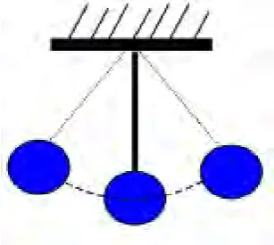
2.1 Swinging of the pendulum 5
2.2 The free vibration of a point mass ith viscous damping 7 2.3 Free vibration of a point mass without damping 7
2.4 Example of frequency domain analysis graph 10
2.5 Example of the time domain analysis graph 11
2.6 Example of a velocity transducer 14
2.7 Example of two common types of accelerometer 15
2.8 Example of the proximity probes 16
2.9 Example of mechanism of the piezofilm sensor 18
2.10 Experimental Modal Analysis Process 20
2.11 FRF Results for a Test Scenario 21
3.1 Flow chart of this study 26
3.2 Example of impact hammer 27
3.3 Example of piezoelectric film 29
3.4 Example of DAQ 29
3.5 Type of supports and the position of the supports on the specimen 30
3.6 Layout of the experiment set-up 31
4.8 Maximum and minimum value of mechanical properties of Brass
according to CES EduPack 2011 40
4.9 Maximum and minimum value of mechanical properties of Copper
according to CES EduPack 2011 40
4.10 Maximum and minimum value of mechanical properties of
Stainless Steel according to CES EduPack 2011 41
4.11 I-Kaz 4D coefficient of piezofilm sensor versus impact force
applied on the specimens 43
4.12 I-Kaz 4D coefficient of piezofilm sensor versus impact force
applied on the Copper and Stainless Steel specimen 44 4.13 Young modulus versus I-Kaz 4D linear coefficient of vibration signal 46 4.14 Shear modulus versus I-kaz 4D linear coefficient of vibration signal 48 4.15 Tensile Strength versus I-kaz 4D linear coefficient of vibration signal 50 4.16 Compressive strength versus I-kaz 4D linear coefficient of
LIST OF ABBREVIATIONS, SYMBOLS AND
NOMENCLATURE
AE - Acoustic Emission Testing
ADC - Analog-To-Digital
DSA - Dynamic Signal Analyzers
ET - Electromagnetic Testing
ETC - Et Cetera
FM - Freqeuncy Modulation
FFT - Fast Fourier Transfer
FRF - Frequency Response Function
IR - Thermal/Infrared Testing
ICP - Inductively Coupled Plasma
IEPE - Integrated Electronics Piezo Electric
MATLAB - Matrix Laboratory
MFL - Magnetic Flux Leakage
MHz - Megahertz
MT - Magnetic Particle Testing
Mv - Medium Voltage
NDT - Non-Destructive Test
PT - Liquid Penetrant Testing
PC - Personal Computer
RT - Radiographic Testing
SISO - Single Input And Single Output
TM - Tympanic Layer
TFM - Transfer Function Model
UT - Ultrasonic Testing
VA - Vibration Analysis
mm - Millimiter
°C - Celcius
m / s2 - Meter Per Second Square
CHAPTER 1
INTRODUCTION
1.0 Background
The law of nature has been states that everything has a vibration. Can be say that mostly of the engineering structures and machines experience vibrations to some of degree and their design usually requires consideration of their oscillatory motion. Before this, to do research on related to the vibration a destructive test has be conducted where the test has a lot of disadvantage such as could lead to higher cost and to complete the test it required a long time. To prevent this from happening a new method has been used by using Non-Destructive Test (NDT) method which can do those test without destroying the material.
Basically, the process of NDT are involving of evaluating materials, testing or assemblies or inspecting the components for discontinuities, without destroying the serviceability of the system or part or in a simplest word is the part or component still can be used without damaging or having a defect on it after completing the testing. There are several NDT testing that be using nowdays such as Electromagnetic Testing (ET), Acoustic Emission Testing (AE), Liquid Penetrant Testing (PT), Visual Testing (VT), Radiographic Testing (RT), Thermal/Infrared Testing (IR), Magnetic Particle Testing (MT), Magnetic Flux Leakage (MFL), Vibration Analysis (VA) and Ultrasonic Testing (UT). However, in this study will be focused on a Vibration Analysis Method.
NDT implementation is important in order to describe what should be found and what to reject. A totally immaculate production is never conceivable. Consequently testing particulars are key. These days there exist an extraordinary number of measures and acknowledgment regulations. Often which specific NDT
In addition, there a lot of reason or advantages to do Non-Destructive Test compare to the destructive testing method. The advantages of implementing the NDT
is Cawley’s stated that, a vibration technique for non-destructively evaluating the integrity of structures is described and applied to components fabricated and the method uses measurements of changes in the lower structural natural frequencies, which can be made at a single point in the structure, in conjunction with a dynamic analysis of the system to detect, locate and roughly to quantify damage (Cawley, 1979). Besides that, with just one test it can have more variety of result mechanical properties characteristic and it also easy to find the natural frequency for a given material. Non-Destructive Test (NDT) it is method that refers to the type of equipment that penetrates the material used to perform the test.
Furthermore, NDT tests result can prevent in to the replacement or repair of machine before malfunction can occur. For an example, oil spill a reliable non-destructive testing of the cement seals and blowout preventers on the Deepwater Horizon could have meant an incalculable amount of money that will be saved. NDT
technique testing is more reliable than DT technique due to the variety of available and complementary options. NDT technique also can eliminate the risk of inaccuracy or oversight. After all of these advantages that’s why the NDT technique is choosen for this study. By doing this study the result that obtained will be compare with the result of Destructive Test value to know the material properties on a material.
1.1 Problem Statement
severe operating conditions and it is continued until the application breaks. In order to determine the service life of the product or to determine the design weaknesses if any which may not show up under normal working conditions those two reason are main purpose why destructive test is needed.
However, destructive testing (DT) has a lot of disadvantages compare to the
NDT technique such as there are many flaws in the high cost of manufacturing machinery and equipment, and also there is a universal testing machine that are available on the market use only one test at a testing method results only which could lead to wasting time. By doing destructive test also the material or part that being used for the testing cannot be used anymore and if the testing is fail it need to do it again and again until it reach the result that wanted thus this could increase cost for the manufacturer.
Furthermore, to set up the experiments also quite complicated and requires a relatively long time to complete the experiment and it will take time. Besides that, the destructive test also only can detect certain test for example tensile test or hardness test and the test only valid for one time only. To overcome this problem a (NDT) Non-Destructive Test has been selected as it has the advantage of as the method requires no great skill and is easy to understand that any individual can do this test. By using this method it can save time whereby with just one software it can make different test at the same time. In addition, this technique also can saving time whereby the test can do for a several testing.
1.2 Objective
The objective for this study is stated below whereby this study contain two objective which is:
To obtain its material properties characteristic of brass material.
1.3 Scope
The process will start with the preparation of the sample. The sample that will be used is from the piece of brass material that in a square shape with a dimension of 300 mm length and 300 mm height with the thickness is 1.5 mm (300 mm X 1.5 mm
CHAPTER 2
LITERATURE REVIEW
2.0 Introduction of Vibration
[image:21.595.251.405.556.693.2]In simplest terms, any movement that more than once itself after an interim time is called vibration. The simplest example is on Figure 2.1 whereby it shows the swinging of a pendulum and the movement of a plucked string. Theory of vibration manages the investigation of oscillatory movement of bodies and strengths related with them. Kelly (2012) stated that, vibrations are occur in many structural and mechanical systems but, if it is uncontrolled, the vibration can lead to catastrophic situations whereby the vibrations that exist at the machine tools or machine tool chatter can lead to improper machining of parts. Besides that, during earthquakes or even wind-induced vibration the structural failure can happen due to the large dynamic stresses developed.
2.1 Type of Vibration
Engineers nowadays may encounter one of the most difficult things that need to be resolved during the time which is the problem are vibration. There are many different types of vibration, but if the vibration are classified in the wrong place it will be terrible for machines. For example, the vibration will cause a machine to breakdown and causing the machine to make louder noise when running. In addition, a major structure such as a bridge, if the wrong type of vibration occur it can cause a damage that could lead to fatal. There are many types of vibration that have developed over the years.
2.1.1 Free Vibration
Rohal’ and Ilkiv (2012) stated that, free vibration happens when a mechanical system are energized by the beginning condition, for example, a velocity, acceleration or displacement and along these lines enabling it to vibrate freely without proceeded continued force interaction. In addition, the examples of this type of vibration are like on a tuning fork and after that let the ring pull back the tyke on a swing and letting go. The mechanical framework vibrates at least one of its regular frequencies and damps down to motionless.
2.1.1.1 Free Vibration With Damping
schematically is shown by Fig. 2.2 whereby it is free vibration of a point mass with viscous damping.
[image:23.595.182.482.139.297.2]Fb = b
= b ˙ q(t)
Figure 2.2: The free vibration of a point mass with viscous damping (Rohal’ and Ilkiv, 2012)
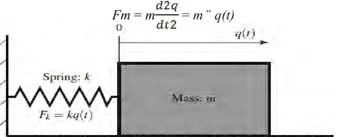
2.1.1.2 Free Vibration Without Damping
Based on Rohal’-Ilkiv (2012), a system that had been show in Fig. 2.2. Shows that the damping is not being used and there are no external force acting on it. For the vibrating mass, it is often to be referred as a simple harmonic oscillator, however it is sliding on a frictionless surface and has a mass of m. The position of the mass is signified by dependent coordinate, q (t). In the meantime, the mass are connected with the surface with a linear spring and have the spring constant (k).
Fm = m
= m ¨ q(t)
[image:23.595.144.488.587.725.2]2.1.2 Forced Vibration
Forced vibration in a simplest definition is the vibration that happens under the excitation of outer force. Blake (2010) stated that, all real systems have some damping, even though it is often very small. However, a small damping forces also can affect the forced response around resonance, this can be helpful to be able to merge them into theoretical model and investigate damped forced vibration. The examples of this forced vibration include car vibration caused by an engine, a shaking clothes washer because of an irregularity, or vibration of a building cause by an earthquake.
2.1.3 Damped Vibration
According to Blake (2010), at the point when the vitality of a vibrating system is step by step it will be annihilated by grinding and other resistance, so the vibrations are said to be damped. Moreover, the vibrations slowly change or being lessen in recurrence and the framework will be rests in its equilibrium position.
2.2 Vibration Analysis