This is a repository copy of
Speed Control of Non-collocated Stator-Rotor Synchronous
Motor with Application in Robotic Surgery
.
White Rose Research Online URL for this paper:
http://eprints.whiterose.ac.uk/113726/
Version: Accepted Version
Proceedings Paper:
Mohammadi, A, Samsonas, D, Di Natali, C et al. (3 more authors) (2015) Speed Control of
Non-collocated Stator-Rotor Synchronous Motor with Application in Robotic Surgery. In:
2015 10th Asian Control Conference: Emerging Control Techniques for a Sustainable
World, ASCC 2015. 2015 10TH Asian Control Conference (ASCC), 31 May - 03 Jun 2015,
Kota Kinabalu, Malaysia. IEEE . ISBN 978-1-4799-7862-5
https://doi.org/10.1109/ASCC.2015.7244830
(c) 2015 IEEE. Personal use of this material is permitted. Permission from IEEE must be
obtained for all other users, including reprinting/ republishing this material for advertising or
promotional purposes, creating new collective works for resale or redistribution to servers
or lists, or reuse of any copyrighted components of this work in other works.
[email protected] https://eprints.whiterose.ac.uk/
Reuse
Unless indicated otherwise, fulltext items are protected by copyright with all rights reserved. The copyright exception in section 29 of the Copyright, Designs and Patents Act 1988 allows the making of a single copy solely for the purpose of non-commercial research or private study within the limits of fair dealing. The publisher or other rights-holder may allow further reproduction and re-use of this version - refer to the White Rose Research Online record for this item. Where records identify the publisher as the copyright holder, users can verify any specific terms of use on the publisher’s website.
Takedown
If you consider content in White Rose Research Online to be in breach of UK law, please notify us by
Speed Control of Non-collocated Stator-Rotor
Synchronous Motor with Application in Robotic
Surgery
Alireza Mohammadi
∗, Danielius Samsonas
∗, Christian Di Natali
†, Pietro Valdastri
†, Ying Tan
∗, Denny Oetomo
∗∗Melbourne School of Engineering, The University of Melbourne, Melbourne, Australia
†Department of Mechanical Engineering, Vanderbilt University, Nashville, TN, USA
Email: [email protected] and [email protected]
Abstract—This paper introduces Non-collocated Stator-Rotor Synchronous Motor (NSRSM) as a novel actuation system for cases where the stator and rotor are required to interact across a physical barrier. The main motivation for NSRSM is in the area of laparoscopic robotic surgery whereby it is desired to actuate the manipulators across the abdominal wall, but it also has potential application in other robotic surgery procedures. The configuration of NSRSM is similar to that of permanent magnet synchronous motor (PMSM) although due to asymmetric structure of the windings around the rotor, the electromechanical model of PMSMs was developed to obtain the dynamic model of NSRSM. Thefield oriented controlmethod is used to develop an appropriate model for control purposes. Then two widely used control algorithms (PI controller and linear quadratic regulator (LQR)) are used to control the rotor speed in the presence of the modelling uncertainties and load disturbances. Simulation results show that these two methods are robust.
Keywords—Permanet magnet synchronous motor, robotic surgery, field oriented control, LQR.
I. INTRODUCTION
In the last decade, surgical advances have focused on techniques to minimise the invasiveness of operations in order to reduce the resulting trauma; such as advances in laparoscopic techniques [7]. Current promising approaches are developed in robotic surgery for reducing access trauma using laparoendoscopic single site surgery [1]. In these cases, the robotic manipulators are actuated through on-board motors. However, the performance of the motors that can fit through the small (20mm) incision is limited.
In one of the most recent studies [9], the authors proposed a novel approach called Local Magnetic Actuation (LMA) to transfer mechanical power across the abdominal wall by a magnetic coupling which eliminates the need for embedded actuators and wired connections. The LMA is composed of an anchoring unit to support the instrument during the surgery and an actuation unit to transfer power to internal driven magnet via rotating external driving magnet. The technique has the advantage of requiring only one incision through which the (internal) surgical units can be inserted and then actuated from outside the abdominal wall. Additionally, stator components of the actuations can be placed outside the abdominal cavity, thus allowing space saving within the cavity and the use of larger external actuation components capable of delivering higher performance.
ߙ
ߠ ܯ
Abdominal Wall
ߙ
[image:2.612.340.552.228.379.2]Abdom ݅
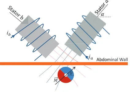
Fig. 1. Schematic of Non-collocated rotor and stator
The magnetic field linkage is inversely proportional to the thickness of the abdominal wall separating the external magnets and the internal magnets in the LMA technique [9]. Therefore, in a larger distance, the provided torque will be
small. In addition, increasing the load torque can cause pole
slipping between external and internal driving magnets and consequently reducing the amount of transferred torque sig-nificantly. Misalignment of rotational axis of two permanents magnets is also another issue with LMA. The LMA system in [9] consists of permanent magnets, therefore is unable to compensate for these variations in physical parameters conveniently.
The structure of the proposed actuation system in Fig. 1 is similar to that of Permanent Magnet Synchronous Motor (PMSM) although there is a significant difference. In PMSMs, the stator coils surround the entire circumference of the perma-nent magnet rotor in a circular and symmetric manner while in the proposed system, stator coils can only be located to one side of the rotor, which is the side facing the abdominal wall. For this reason, the proposed system is tentatively labelled Non-collocated Stator-Rotor Synchronous Motor (NSRSM).
Since it is not possible, or at least inconvenient, to place more stator coils on the other side of the rotor in the NSRSM design, there is no physical symmetry in its structure. Having no symmetry causes more severe torque ripple compared to conventional motors. In addition, due to the variation in distance between stator and rotor of NSRSM, the parameters of the model is time-varying. Due to these differences, the model of PMSMs and their control schemes cannot be directly used for NSRSM.
Therefore, the first purpose of this paper is to develop the electromechanical model of NSRSM using the model of PMSMs. This model should be simple for control purposes while it captures all the important dynamic characteristics of NSRSM. The second objective of this study is to propose appropriate control schemes to generate a smooth torque with taking into account the asymmetric structure of NSRSM.
In PMSMs, since the back-emf voltage is sinusoidal, the controller should attempt to provide sinusoidal current signals with an appropriate relative phases such that permanent magnet rotate smoothly. The conventional control method is to feed desired sinusoidal current signals to a pair of PI controllers to regulate current signal in each coil. This will result in a smooth rotation provided that the output current waveform accurately track the desired sinusoidal signal. However, the main problem with this method is that the controller attempts to track a time-varying signal which in general is difficult
in high speeds [6]. The field oriented control can solve this
problem by controlling the current signals in a new coordinate system rotating with rotor speed [5]. In this coordinate, the current signals are constant and independent of rotor position. Consequently, performance of the controllers are generally independent of the speed of the rotor. Then, well-established control methods can be employed for current control in the coils.
Although the back-emf voltage in NSRSM in sinusoidal similar to PMSMs, the PMSM control schemes cannot be directly applied to NSRSM due to its asymmetric structure and variable model parameters as mentioned above. Therefore, an appropriate control schemes should be proposed to generate a smooth torque and these controllers should be robust enough to track a desired speed in the presence of load disturbance and model uncertainties.
II. DYNAMICMODEL OFNSRSM
The schematic diagram of the proposed NSRSM is depicted in Fig. 1. NSRSM has at least two stator windings labelled as stator a and stator b and a permanent magnet as rotor. Two electromagnetic coils were used to produce a unique motion (speed and direction of rotation) of the rotor, located across the
Pgv"uvcvqt"" ewttgpv""
[image:3.612.367.524.56.200.2]xgevqt"
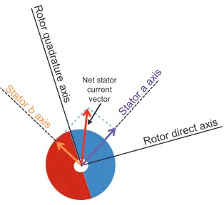
Fig. 2. The schematic of the net stator current vector based on current vectors of stator a and stator b
abdominal wall. The electrical equations of NSRSM is similar to PMSM and can be represented as [10]:
va = Rsia+Ladia
dt +ea, (1)
vb = Rsib+Lbdib
dt +eb, (2)
whereva andvb are the stator phase voltages,Rsis the stator
resistance per phase,ia andib are the stator phase currents,La
and Lb are the self-inductance of phases a andb andea and
eb are the phase back electromotive forces (back-emfs) which
are as follows:
ea = ωλmsin(θ), (3)
eb = ωλmsin(θ−π
2). (4)
whereωis the angular speed of the rotor,λmis the flux linkage
of the permanent magnet and θ is the rotor position.
The dynamic motion of the permanent magnet rotor can be represented as:
Jdω
dt +bω=Te−Tl−Tcog (5)
where J is the total moment of inertia, b is the friction
coefficient, Te is the electromagnetic torque, Tl is the load
torque and Tcog is the cogging torque.
In this paper the following assumptions are considered for NSRSM:
• The resistance and inductance of two coils are equal
(La =Lb=L),
• The mutual inductance is small,
• The cogging torque is negligible (Tcog= 0).
The electromagnetic torque,Te, is the consequence of the
interaction between of the permanent magnet field,−M→, and the
stator magnetic field,−→B, which can be represented as:
Te=−M→×−→B. (6)
the other hand, if two fields are parallel to each other, no torque is produced. Since the magnetic fields of the coils are proportional to the current, it is more convenient to use coil currents instead of magnetic field of the coils. As a result, the net stator current can be considered as a vector which is aligned at the direction of the net stator field as shown in Fig. 2. The purpose of NSRSM control is that, in each position of rotor, produce current signals in coils such that the current vector is orthogonal to the permanent magnet rotor axis. The stator current can be divided to two orthogonal components in parallel and perpendicular to the axis of the rotor labeled as quadrature and direct. Therefore, the control goal will be simplified to producing current signals such that the current in direct direction is zero. Consequently, the produced torque is proportional to the current in the quadrature direction.
Similar to PMSMs, the electromagnetic torque,Te, in terms
of current, back-emf and rotor speed can be expressed as [10]:
Te= (eaia+ebib)/ω. (7)
Then, substituting (3)-(4) in the above equation gives:
Te=λm(sin(θ)ia+ sin(θ−π
2)ib). (8)
This equation also shows that the torque is a function of rotor
position, θ, and in each position of rotor, there are optimal
values of the current vectorsia andibthat provides maximum
torque. Therefore, in order to produce maximum torque, the current signal should be generated as:
ia = Issin(ωt) (9)
ib = Issin(ωt−π
2) (10)
whereIsis the stator current. Substituting the above equations
in the torque equation (7) results in:
Te=λmIs(sin2(ωt) + sin2(ωt−π
2)) =λmIs. (11)
PMSMs have at leastN stator coils surrounding the rotor,
N ≥ 3, where the stator coils are arranged evenly 360/N
degrees apart from each other. Therefore, current signals are
phase shifted360/Ndegrees while in NSRSM the coils should
be oriented on axes with 90 degrees angle between them (see Fig. 1) and then current signals should be phase shifted 90 degrees from the other one.
Equation (11) shows that in order to produce constant smooth torque without rippling, the current signals (9), (10) should be constant in magnitude and frequency, irrespective of rotor position. This requires very accurate measurement of currents and rotor position and in cases that desired torque changes, tracking of time-varying current signal is required. This is achievable in low speeds, however, as motor speed increases, the controller should track a sinusoidal current signal with increasing frequency. Also, the controller should overcome the variation in amplitude and frequency of back-emf as speed changes. Field-oriented control can address this problem by controlling current signals in the rotating d-q frame which is explained in the next section.
III. FIELD-ORIENTEDCONTROL
Since electrical equations represented above are dependent on position of permanent magnet flux, it is not easy to design a speed or torque controller with well-established control methods. The main goal of field-oriented control (FOC) is to decouple torque (quadrature) and magnetising flux (direct) components of the stator magnetic field, as shown in Fig. 2, and therefore remove the dependency to rotor position by
projecting the system equations in d-q system that rotates
at the speed of the rotor. This projection is known as Park transformation which is given by [6]:
iq = −sin(θ)ia+ cos(θ)ib, (12)
id = cos(θ)ia+ sin(θ)ib. (13)
In this new coordinate system, the electrical equations are represented as:
vq = Rsiq+Lqdiq
dt +ωλd, (14)
vd = Rsid+Lddid
dt −ωλq, (15)
where
λq = Lqiq, (16)
λd = Ldid+λm, (17)
vd and vq are the d, q axis voltages, id and iq are the d, q
axis stator currents, Ld andLq are the d, q axis inductances
and λm is the flux linkage due to the rotor magnets linking
the stator.
Also, the electromagnetic torque in this new reference frame is:
Te=λdiq−λqid. (18)
Based on equation (18), in order to produce maximum
torque for a given stator current, the current in d-axis should
be set to zero.
Considering equations (14), (15) and (18), system dyna-mics can be expressed in state-space form as:
diq
dt = (vq−Rsiq−ω−Ldωid−λmω)/Lq, (19) did
dt = (vd−Rsid+Lqωiq)/Ld, (20)
dω
dt = (Te−Tl−bω)/J. (21)
In order to find the currents and voltages in a-b coordinate, the following inverse Park transformation can be applied:
Sa Sb
=
−sin(θ) cos(θ)
cos(θ) sin(θ)
Sq Sd
,
[image:4.612.346.570.577.641.2]RK"
RK" d,q
a,b RK"
d,q
a,b
RYO" Oqfwncvkqp"
߱
݀ ݀ݐ"
ߠ ߱
െ െ
െ
݅ௗ
݅
݅
݅ௗ
ݒ
ݒ
ݒ
ݒௗ
Encoder co E d
݅
[image:5.612.103.524.60.244.2]݅
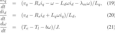
Fig. 3. The basic scheme of FOC with PI-based controller
IV. PI-BASEDCONTROLLERDESIGN
As mentioned in the previous section, after expressing the
electromechanical equations ind-qreference frame, the control
goal is to control voltage signalsvqandvdsuch that the current
id is zero for a desired speed and torque command. Fig. 3
shows the basic schematic of implementation of PI-based FOC for NSRSM. The required measurements for this control are currents of two coils and rotor position. The measured currents,
ia andib, are feed to the Park transformation and its output,
iq andidare compared to iqref andidref and fed back to the
PI controllers. The iqref signal is produced by the required
torque demanded by the speed regulator and idref should be
set to zero as explained in the previous section. The outputs of
the current controller, vq andvd are fed into the inverse Park
transformation and then applied to the coils as va andvb. It
should be noted that both Park and inverse Park transformation require the rotor position which can provided by a Hall effect sensor. The derivative of the position signal is also used as rotor speed feedback signal.
This control scheme consists of two control loops: the inner control loop that regulates current signals and the outer velocity control loop that attains the desired velocity. Both of these controllers are based on conventional proportional-integral (PI) with velocity and currents as feedback. Therefore, the control laws for the current signals and the rotor velocity are:
vq = Kpq˜iq+Kiq
˜iqdt, (22)
vd = Kpd˜id+Kid
˜iddt, (23)
iqref = Kpωω˜+Kiω
˜
ωdt, (24)
where˜iq = iq −iqref,˜id =id−idref, ω˜ = ω−ωref and
(Kpq, Kiq),(Kpd, Kid)and(Kpω, Kiω)are proportional and integral gains of quadrature current, direct current and rotor speed, respectively.
V. LQR-BASEDCONTROLLERDESIGN
PI controllers are widely applied in control of industrial systems due to their simple structure and good performance
without requiring a priori knowledge about the plant model.
However, it is difficult to tune the controller gains and there is no guarantee regarding performance and stability of the system.
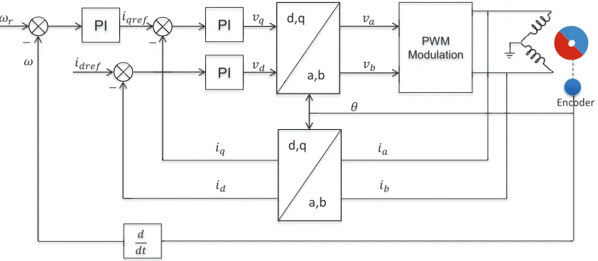
Linear-Quadratic Regulator (LQR) can address the afore-mentioned problems. The goal of LQR is to find gains of the feedback control such that the given cost function is minimised. As a result, it achieves a compromise between the control effort and tracking performance that will guarantee stable performance of the system. In this method, the inner and outer layers of the control will be replaced by one controller
that regulates the rotor speed, ω, and current signal in direct
axis, id.
The design procedure in LQR requires a linear model of the system. Therefore, the nonlinear system (20)-(21) is linearised
around its equilibrium point at iq=id=ω= 0 which gives:
˙
x = Ax+Bv, (25)
y = Cx, (26)
wherex= [iq id ω]T,v= [vq vd]T and
A= ⎡
⎢ ⎣
−Rs
Lq 0 −
λm
Lq
0 −Rs
Ld 0
λm
J 0 −
b J
⎤
⎥ ⎦,
B= ⎡
⎣ 1
Lq 0
0 1
Ld
0 0
⎤
⎦, C=
0 1 0
0 0 1
Since we want to design a controller that regulates the rotor
velocity to the desired velocity, ωref, and the direct current,
id, to zero, the error system is constructed as:
˙˜
" d,q
a,b
d,q
a,b
RYO" Oqfwncvkqp"
߱
݀ ݀ݐ"
ߠ ߱
െ
݅
݅ௗ
ݒ
ݒ
ݒ
ݒௗ
Encoder co E d
NST" Eqpvtqnngt"
݅
[image:6.612.116.504.59.242.2]݅
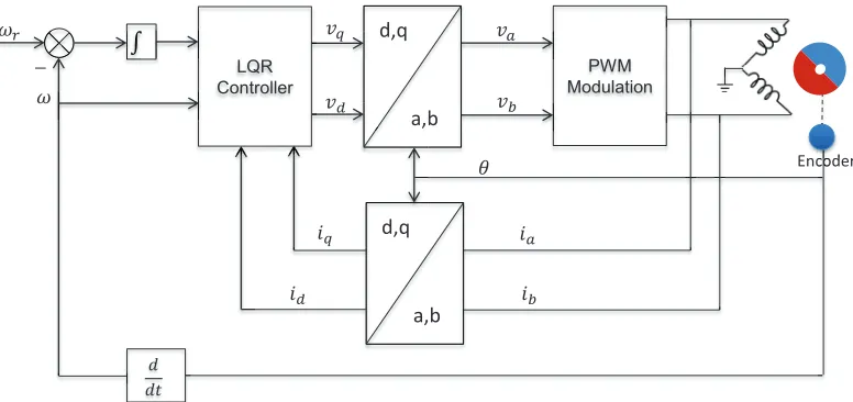
Fig. 4. The scheme of FOC with LQR-based controller
where x˜ = [ ˜iq id˜ ω˜]T,u= [Vq Vd], iq˜ =iq−bωr
λm,
˜
id =id, ˜
ω=ω−ωr,Vq =vq−(bωr
λm +ωrλm)andVd=vd−
−Lqbω2r
λm .
The cost function is considered as:
J(x) =
∞
0
(˜xTQx˜+uTRu)dt (28)
where Q =QT ≥0 and R =RT >0. Then, the feedback
control law that minimises the cost is
v=−K1x,˜ K1=R−1BTP, (29)
and P is found by solving the algebraic Riccati equation
ATP+P A−P BR−1BTP+Q= 0. (30)
The LQR controller can achieve the desired performance and trajectory tracking provided that a perfect model of the system is available. However, in NSRSM, due to variation in distance between the coils and the permanent magnet rotor there are uncertainties in the system model. In addition, there is load disturbances which should be rejected appropriately. A potential solution instead of retuning the feedback gains is to make use of integral action as explained in the next section.
A. Internal Model Principle
In systems that exogenous signals such as desired trajectory and input disturbances are generated by a known model, asymptotic output tracking in the presence of input disturbance can be achieved by including such model in the feedback controller. This method is known as internal model principle (IMP) [3]. In the cases that the exogenous signals are constant, asymptotic regulation of output to the desired trajectory and disturbance rejection can be achieved by including integral action in the control.
In order to introduce the integral action, the regulation
error, e=y−r wherer= [id ω], is integrated and therefore
the augmented model is obtained as: ˙˜
x = Ax˜+Bu, (31)
˙
σ = e. (32)
Given the augmented system, the feedback control law is of the form
u=−K1x˜+K2σ (33)
where K1 is the LQR state feedback term and K2 is the
integral term.
This controller guarantees asymptotically stable equilib-rium point of the augmented system. As a result, although parameter uncertainties of the model will change the
equilib-rium point, the conditione= 0warrants the trajectory tracking
in the presence of parameter uncertainties of the model. The schematic of this controller scheme is shown in Fig. 4.
VI. SIMULATIONRESULTS
In this section, the proposed control schemes are tested through simulations. The NSRSM is required to track a desired
speed, ωr = 20rad/s. For the simulation purposes, the
[image:6.612.341.548.536.602.2]parameters of the NSRSM model are considered as Table. I similar to [8].
TABLE I. MODEL PARAMETERS OFNSRSM
Resistance (Rs) 0.8Ω
Inductance (L) 60mH
Friction Coefficient (b) 0.0000828N ms
Total Moment of Inertia (J) 0.56×10⁻⁶kgm2
Flux Linkage of Permanent Magnet (λm) 0.007V /rad/s
In order to investigate the robustness of the designed controllers in the presence of load disturbances, a disturbance
torque Tl = 3mN m is applied at t = 1sec. In addition,
as mentioned in Introduction, depending of the thickness of abdomen wall, the distance between stator and rotor is variable. This variation has a direct influence on back-emf voltage and electromagnetic torque due to variation in flux
linkage of permanent magnet,λm. Therefore, the performance
of the control schemes are also assessed in terms of model
uncertainties by varying value of λm from 0.007 to0.005 at
2 207 3 307 4 407 5 "*tc f1 u+ /7 2 7 32 37 42 47
2 207 3 307 4 407 5
xc "c pf "xd "*X+ /4 /3 2 3 4 5 6 7
xc"
xd"
Vkog"*uge+
2 207 3 307 4 407 5
xs "c pf "xf "*X+ /3 2 3 4 5 6 7
xs"
xf"
*c+
*d+
[image:7.612.57.296.53.332.2]*e+
Fig. 5. Simulation results of implementation PI controller for speed regulation of NSRSM with torque disturbance att= 1secand parameter variation (λm)
att= 2sec; (a) Rotor speed, (b) Voltage control inputs to stator a and stator
b, (c) Control voltages ind-qcoordination
Based on the parameters of the model in Table I, the gains of PI controller are tuned for the best performance of the controller. The giants of PI controller are obtained as (Kpq = 0.2, Kiq = 1), (Kpd = 1, Kid = 10) and (Kpω = 1, Kiω = 10) for quadrature current, direct current and rotor speed, respectively. As it was expected, the inner loop which includes quadrature and direct current control is faster than the outer speed control. In future, a better and systematic tuning method such as extremum seeking based PI controllers will be explored [4].
The state feedback and integral gains of the LQR-IMP controller are also obtained as:
K1=
10.28 0 0.087
0 0.03 0
, K2=
20 0
0 7
The simulation results are shown in Fig. 5 and Fig. 6. The results show that both PI controllers and LQR controllers work well in the presence of disturbances and uncertainties. These results demonstrate the effectiveness of design procedures. Fine tuning methods will be used in experiments in near future.
VII. CONCLUSIONS
Non-collocated stator-rotor synchronous motor as a novel actuation system in robotic surgery has been introduced in this paper. The dynamic model of this system and two control schemes, PI and LQR-IMP, have been presented. The simula-tion results show that both of controllers can track the desired angular velocity of rotor and handle the load disturbances and uncertainties in the model parameters.
2 207 3 307 4 407 5
"*tc f1 u+ /7 2 7 32 37 42 47
2 207 3 307 4 407 5
xc "c pf "xd "*X+ /3 2 3 4 5 6 7
xc" xd"
Vkog"*uge+
2 207 3 307 4 407 5
xs "c pf "xf "*X+ /3 2 3 4 5 6 7
xs" xf" *c+
*d+
*e+
Fig. 6. Simulation results of implementation LQR-IMP controller for speed regulation of NSRSM with torque disturbance at t= 1sec and parameter
variation (λm) att= 2sec; (a) Rotor speed, (b) Voltage control inputs to
stator a and stator b, (c) Control voltages ind-qcoordination
REFERENCES
[1] Fader, A. N. and Escobar, P. F., “Laparoendoscopic single-site surgery (LESS) in gynecologic oncology: technique and initial report”, Gyneco-logic Oncology, vol. 114, no. 2, pp. 157-161, 2009.
[2] Garbin, N., Di Natali, C., Buzzi, J., De Momi, E. and Valdastri, P., “Laparoscopic Tissue Retractor Based on Local Magnetic Actuation”,
Journal of Medical Devices, vol. 9, no. 1, 011005, 2015.
[3] Khalil, H.,Nonlinear Systems, 3rd ed, Upper Saddle River: Prentice hall, 2002.
[4] Killingsworth, N. J. and Krstic, M., “PID tuning using extremum seeking: online, model-free performance optimization”, IEEE Transactions on Control Systems, vol. 26, no. 1, pp. 70-79, 2006.
[5] Kubota, K., and Matsuse, K., “Speed sensorless field-oriented control of induction motor with rotor resistance adaptation”,IEEE Transactions on Industry Applications, vol. 30, no. 5, pp.1219-1224, 1994.
[6] Low, T. S., Lee, T. H., Tseng, K. J. and Lock, K. S., “Servo Performance of a BLDC Drive with Instantaneous Torque Control”,IEEE Transactions on Industry Applications, vol. 28, no. 2, pp. 455-462, 1992.
[7] Mack, M. J., “Minimally invasive and robotic surgery”,Journal of the American Medical Association, vol. 285, no. 5, pp. 568-572, 2001. [8] Mohammadi, A., Di Natali, C., Samsonas, D., Valdastri P., Tan, Y.
and Oetomo, D., “Electromagnetic Actuator across Abdominal Wall for Minimally Invasive Robotic Surgery”, Accepted in ASME Journal of Medical Devices, 2014.
[9] Natali, C. Di, Ranzani, T., Simi, M., Menciassi, A., and Valdastri, P., “Trans-abdominal active magnetic linkage for robotic surgery: Concept definition and model assessment”, in Proceedings of IEEE International Conference on Robotics and Automation, pp. 695-700, 2012.
[image:7.612.331.562.55.327.2]