73761101 pdf
122
0
0
Full text
(2) Revision History Revision. Revision History. Date. -001. Released Version. November 1999. This product specification applies only to standard VC820 desktop boards with BIOS identifier VC82010A.86A. Changes to this specification will be published in the Intel Desktop Board VC820 Specification Update before being incorporated into a revision of this document.. Information in this document is provided in connection with Intel® products. No license, express or implied, by estoppel or otherwise, to any intellectual property rights is granted by this document. Except as provided in Intel’s Terms and Conditions of Sale for such products, Intel assumes no liability whatsoever, and Intel disclaims any express or implied warranty, relating to sale and/or use of Intel products including liability or warranties relating to fitness for a particular purpose, merchantability, or infringement of any patent, copyright or other intellectual property right. Intel products are not intended for use in medical, life saving, or life sustaining applications. Intel may make changes to specifications and product descriptions at any time, without notice. The VC820 desktop board may contain design defects or errors known as errata that may cause the product to deviate from published specifications. Current characterized errata are available on request. Contact your local Intel sales office or your distributor to obtain the latest specifications before placing your product order. Copies of documents which have an ordering number and are referenced in this document, or other Intel literature, may be obtained from: Intel Corporation P.O. Box 5937 Denver, CO 80217-9808 or call in North America 1-800-548-4725, Europe 44-0-1793-431-155, France 44-0-1793-421-777, Germany 44-0-1793-421-333, other Countries 708-296-9333. †. Third-party brands and names are the property of their respective owners.. Copyright 1999, Intel Corporation. All rights reserved..
(3) Preface This Technical Product Specification (TPS) specifies the board layout, components, connectors, power and environmental requirements, and the BIOS for the Intel Desktop Board VC820. It describes the standard VC820 board product.. Intended Audience The TPS is intended to provide detailed, technical information about the VC820 board and its components to the vendors, system integrators, and other engineers and technicians who need this level of information. It is specifically not intended for general audiences.. What This Document Contains Chapter 1 2 3 4 5. Description A description of the hardware used on this board A map of the resources of the board The features supported by the BIOS Setup program The contents of the BIOS Setup program’s menus and submenus A description of the BIOS error messages, beep codes, POST codes, and enhanced diagnostics. Typographical Conventions This section contains information about the conventions used in this specification. Not all of these symbols and abbreviations appear in all specifications of this type.. Notes, Cautions, and Warnings. ✏. NOTE Notes call attention to important information.. CAUTION Cautions are included to help you avoid damaging hardware or losing data.. WARNING Warnings indicate conditions, which if not observed, can cause personal injury.. iii.
(4) Intel Desktop Board VC820 Technical Product Specification. Other Common Notation. iv. #. Used after a signal name to identify an active-low signal (such as USBP0#). (NxnX). When used in the description of a component, N indicates component type, xn are the relative coordinates of its location on the board, and X is the instance of the particular part at that general location. For example, J5J1 is a connector, located at 5J. It is the first connector in the 5J area.. KB. Kilobyte (1024 bytes). Kbit. Kilobit (1024 bits). MB. Megabyte (1,048,576 bytes). Mbit. Megabit (1,048,576 bits). GB. Gigabyte (1,073,741,824 bytes). xxh. An address or data value ending with a lowercase h indicates a hexadecimal value.. x.x V. Volts. All voltages are DC unless otherwise specified.. †. This symbol is used to indicate third-party brands and names that are the property of their respective owners..
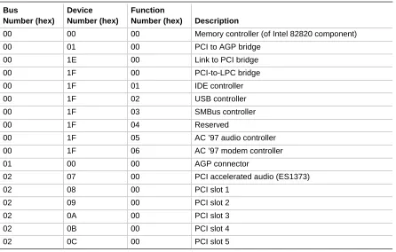
(5) Contents 1 Product Description 1.1. Overview ................................................................................................................... 12 1.1.1 Feature Summary ....................................................................................... 12 1.1.2 VC820 Desktop Board Layout ..................................................................... 14 1.1.3 Block Diagram ............................................................................................. 15 1.2 Online Support........................................................................................................... 16 1.3 Design Specifications ................................................................................................ 16 1.4 Processor .................................................................................................................. 19 1.5 System Memory......................................................................................................... 20 1.5.1 RDRAM Terminology .................................................................................. 20 1.5.2 Memory Features ........................................................................................ 20 1.5.3 Continuity RIMM Modules ........................................................................... 21 1.5.4 RDRAM Memory Configuration ................................................................... 21 1.5.5 Memory Bus Frequencies............................................................................ 22 1.5.6 ECC Memory............................................................................................... 22 1.6 Intel® 820 Chipset...................................................................................................... 23 1.6.1 AGP ............................................................................................................ 24 1.6.2 USB............................................................................................................. 24 1.6.3 IDE Support................................................................................................. 25 1.6.4 Real-Time Clock, CMOS SRAM, and Battery.............................................. 25 1.7 I/O Controller ............................................................................................................. 26 1.7.1 Serial Ports.................................................................................................. 27 1.7.2 Infrared Support .......................................................................................... 27 1.7.3 Parallel Port................................................................................................. 27 1.7.4 Diskette Drive Controller.............................................................................. 28 1.7.5 Keyboard and Mouse Interface ................................................................... 28 1.8 Audio ......................................................................................................................... 29 1.8.1 Enhanced PCI Audio Subsystem................................................................. 29 1.8.2 Audio Connectors........................................................................................ 31 1.9 Hardware Management Features .............................................................................. 33 1.9.1 Hardware Monitor Component .................................................................... 33 1.9.2 Chassis Intrusion Detect Connector ............................................................ 33 1.10 Power Management Features.................................................................................... 34 1.10.1 Software Support ........................................................................................ 34 1.10.2 Hardware Support ....................................................................................... 37. 2 Technical Reference 2.1 2.2 2.3 2.4 2.5 2.6. Introduction................................................................................................................ 43 Memory Map ............................................................................................................. 43 I/O Map ..................................................................................................................... 44 DMA Channels .......................................................................................................... 46 PCI Configuration Space Map ................................................................................... 46 Interrupts ................................................................................................................... 47. v.
(6) Intel Desktop Board VC820 Technical Product Specification. 2.7 2.8. 2.9 2.10. 2.11. 2.12 2.13 2.14 2.15. PCI Interrupt Routing Map ......................................................................................... 47 Connectors ................................................................................................................ 49 2.8.1 Back Panel Connectors ............................................................................... 50 2.8.2 Midboard Connectors .................................................................................. 54 2.8.3 Front Panel Connectors .............................................................................. 67 Jumper Blocks ........................................................................................................... 70 Mechanical Considerations........................................................................................ 72 2.10.1 Form Factor................................................................................................. 72 2.10.2 I/O Shield .................................................................................................... 73 Electrical Considerations ........................................................................................... 74 2.11.1 Power Consumption .................................................................................... 74 2.11.2 Add-in Board Considerations....................................................................... 75 2.11.3 Standby Current Requirements ................................................................... 75 2.11.4 Fan Power Requirements............................................................................ 76 2.11.5 Power Supply Considerations...................................................................... 77 Thermal Considerations............................................................................................. 78 Reliability ................................................................................................................... 79 Environmental............................................................................................................ 80 Regulatory Compliance ............................................................................................. 81 2.15.1 Safety Regulations ...................................................................................... 81 2.15.2 EMC Regulations ........................................................................................ 81 2.15.3 Certification Markings.................................................................................. 82. 3 Overview of BIOS Features 3.1 3.2 3.3. 3.4 3.5. 3.6 3.7. 3.8 3.9. Introduction................................................................................................................ 83 BIOS Flash Memory Organization ............................................................................. 84 Resource Configuration ............................................................................................. 84 3.3.1 PCI Autoconfiguration ................................................................................. 84 3.3.2 PCI IDE Support.......................................................................................... 85 System Management BIOS (SMBIOS) ...................................................................... 86 BIOS Upgrades ......................................................................................................... 87 3.5.1 Language Support....................................................................................... 87 3.5.2 Custom Splash Screen................................................................................ 87 Recovering BIOS Data .............................................................................................. 88 Boot Options.............................................................................................................. 89 3.7.1 CD-ROM and Network Boot ........................................................................ 89 3.7.2 Booting Without Attached Devices .............................................................. 89 USB Legacy Support ................................................................................................. 90 BIOS Security Features ............................................................................................. 91. 4 BIOS Setup Program 4.1 4.2 4.3 4.4. vi. Introduction................................................................................................................ 93 Maintenance Menu .................................................................................................... 94 4.2.1 Extended Configuration Submenu............................................................... 95 Main Menu................................................................................................................. 96 Advanced Menu......................................................................................................... 97 4.4.1 PCI Configuration Submenu........................................................................ 98 4.4.2 Boot Configuration Submenu ...................................................................... 99.
(7) Contents. 4.5 4.6 4.7 4.8. 4.4.3 Peripheral Configuration Submenu............................................................ 100 4.4.4 IDE Configuration Submenu...................................................................... 102 4.4.5 Diskette Configuration Submenu ............................................................... 104 4.4.6 Event Log Configuration Submenu............................................................ 105 4.4.7 Video Configuration Submenu................................................................... 106 Security Menu.......................................................................................................... 107 Power Menu ............................................................................................................ 108 Boot Menu ............................................................................................................... 109 4.7.1 IDE Drive Configuration Submenu............................................................. 110 Exit Menu ................................................................................................................ 110. 5 Error Messages and Beep Codes 5.1 5.2 5.3 5.4 5.5 5.6. BIOS Error Messages.............................................................................................. 111 Port 80h POST Codes ............................................................................................. 113 Bus Initialization Checkpoints .................................................................................. 117 Speaker ................................................................................................................... 118 BIOS Beep Codes ................................................................................................... 119 Enhanced Diagnostics ............................................................................................. 120. Figures 1. 2. 3. 4. 5. 6. 7. 8. 9. 10. 11. 12. 13. 14. 15. 16. 17. 18. 19.. VC820 Board Components ........................................................................................ 14 Block Diagram ........................................................................................................... 15 Intel 820 Chipset Block Diagram................................................................................ 23 Block Diagram of AC ’97 V 1.03 Compatible Audio Subsystem with Creative Labs ES1373 Controller and AMR Connector ............................................. 29 Using the Wake on LAN Technology Connector ........................................................ 39 Location of Standby Power Indicator LED ................................................................. 40 Connector Groups ..................................................................................................... 49 Back Panel Connectors ............................................................................................. 50 Audio Connectors ...................................................................................................... 55 Peripheral Interface and Indicator Connectors........................................................... 57 Hardware Control and Power Connectors ................................................................. 60 Add-In Board Connectors .......................................................................................... 63 Front Panel Connectors............................................................................................. 67 Location of the Jumper Block .................................................................................... 70 VC820 Board Dimensions.......................................................................................... 72 I/O Shield Dimensions ............................................................................................... 73 Thermally-sensitive Components............................................................................... 78 Memory Map of the Flash Memory Device ................................................................ 84 Enhanced Diagnostic LEDs ..................................................................................... 120. vii.
(8) Intel Desktop Board VC820 Technical Product Specification. Tables 1. 2. 3. 4. 5. 6. 7. 8. 9. 10. 11. 12. 13. 14. 15. 16. 17. 18. 19. 20. 21. 22. 23. 24. 25. 26. 27. 28. 29. 30. 31. 32. 33. 34. 35. 36. 37. 38. 39. 40. 41. 42. 43. 44. 45. 46.. viii. Feature Summary...................................................................................................... 12 Specifications ............................................................................................................ 16 Supported Processors ............................................................................................... 19 Typical RIMM Module Configurations ........................................................................ 21 Memory Bus Frequency with DRCG (Rambus Clock Generator)............................... 22 Memory Error Detection Mode Established in Setup Program ................................... 22 Effects of Pressing the Power Switch ........................................................................ 35 Power States and Targeted System Power ............................................................... 36 Wake Up Devices and Events ................................................................................... 37 Fan Connector Descriptions ...................................................................................... 38 System Memory Map................................................................................................. 43 I/O Map ..................................................................................................................... 44 DMA Channels .......................................................................................................... 46 PCI Configuration Space Map ................................................................................... 46 Interrupts ................................................................................................................... 47 PCI Interrupt Routing Map ......................................................................................... 48 PS/2 Keyboard/Mouse Connectors............................................................................ 51 USB Connectors........................................................................................................ 51 Parallel Port Connector.............................................................................................. 52 Serial Port Connectors............................................................................................... 52 MIDI/Game Port Connector ....................................................................................... 53 Audio Line Out Connector ......................................................................................... 53 Audio Line In Connector ............................................................................................ 53 Mic In Connector ....................................................................................................... 53 CD-ROM Legacy Style Connector (J2C1) ................................................................. 56 ATAPI CD-ROM Connector (J1F1) ............................................................................ 56 Telephony Connector (J2F1) ..................................................................................... 56 Auxiliary Line In Connector (J2F2)............................................................................. 56 PC/PCI Connector (J7A2).......................................................................................... 56 SCSI LED Connector (J7B3) ..................................................................................... 58 PCI IDE Connectors (J8H1, Primary and J7H1, Secondary) ..................................... 58 Diskette Drive Connector (J8G1) ............................................................................... 59 Power Supply Fan Control Connector (J5L1)............................................................. 61 Processor Fan Connector (J2M1).............................................................................. 61 Power Connector (J7L2)............................................................................................ 61 System Fan Connector (J7L1) ................................................................................... 61 Wake on LAN Technology Connector (J7C1) ............................................................ 62 Wake on Ring Connector (J7B2) ............................................................................... 62 Chassis Intrusion Connector (J7A1) .......................................................................... 62 PCI Bus Connectors (J4A1, J4B1, J4C1, J4D1, J4E1) .............................................. 64 AGP Bus Connector (J5E1) ....................................................................................... 65 Audio/Modem Riser Connector (J3F1)....................................................................... 66 Front Panel Connector (J8G2)................................................................................... 68 States for a Single-colored Power LED...................................................................... 69 States for a Dual-colored Power LED ........................................................................ 69 Auxiliary Front Panel Power LED Connector (J8J1)................................................... 69.
(9) Contents. 47. 48. 49. 50. 51. 52. 53. 54. 55. 56. 57. 58. 59. 60. 61. 62. 63. 64. 65. 66. 67. 68. 69. 70. 71. 72. 73. 74. 75. 76. 77. 78. 79. 80. 81. 82. 83. 84. 85.. S5 Remote Control Jumper Settings (J4A2) .............................................................. 71 BIOS Setup Configuration Jumper Settings (J7B1) ................................................... 71 Typical Power Usage................................................................................................. 74 Maximum Power Supply Current Requirements ........................................................ 74 Maximum PCI Add-in Board Current Load................................................................. 75 Standby Current Requirements ................................................................................. 76 Thermal Considerations for Components .................................................................. 79 VC820 Board Environmental Specifications............................................................... 80 Safety Regulations .................................................................................................... 81 EMC Regulations....................................................................................................... 81 Supervisor and User Password Functions ................................................................. 91 BIOS Setup Program Menu Bar................................................................................. 93 BIOS Setup Program Function Keys ......................................................................... 94 Maintenance Menu .................................................................................................... 94 Extended Configuration Submenu ............................................................................. 95 Main Menu................................................................................................................. 96 Advanced Menu......................................................................................................... 97 PCI Configuration Submenu ...................................................................................... 98 Boot Configuration Submenu..................................................................................... 99 Peripheral Configuration Submenu .......................................................................... 100 IDE Configuration Submenu .................................................................................... 102 IDE Configuration Sub-Submenus ........................................................................... 103 Diskette Configuration Submenu ............................................................................. 104 Event Log Configuration Submenu .......................................................................... 105 Video Configuration Submenu ................................................................................. 106 Security Menu.......................................................................................................... 107 Power Menu ............................................................................................................ 108 Boot Menu ............................................................................................................... 109 IDE Drive Configuration Submenu ........................................................................... 110 Exit Menu ................................................................................................................ 110 BIOS Error Messages.............................................................................................. 111 Uncompressed INIT Code Checkpoints................................................................... 113 Boot Block Recovery Code Checkpoints ................................................................. 113 Runtime Code Uncompressed in F000 Shadow RAM ............................................. 114 Bus Initialization Checkpoints .................................................................................. 117 Upper Nibble High Byte Functions ........................................................................... 117 Lower Nibble High Byte Functions ........................................................................... 118 Beep Codes............................................................................................................. 119 Diagnostic LED Codes............................................................................................. 121. ix.
(10) Intel Desktop Board VC820 Technical Product Specification. x.
(11) 1 Product Description What This Chapter Contains 1.1 1.2 1.3 1.4 1.5 1.6 1.7 1.8 1.9 1.10. Overview ................................................................................................................... 12 Online Support........................................................................................................... 16 Design Specifications ................................................................................................ 16 Processor .................................................................................................................. 19 System Memory......................................................................................................... 20 Intel® 820 Chipset...................................................................................................... 23 I/O Controller ............................................................................................................. 26 Audio ......................................................................................................................... 29 Hardware Management Features .............................................................................. 33 Power Management Features.................................................................................... 34. 11.
(12) Intel Desktop Board VC820 Technical Product Specification. 1.1 Overview 1.1.1. Feature Summary. Table 1 summarizes the VC820 board’s major features. Table 1.. Feature Summary. Form Factor. ATX (12.0 inches by 8.2 inches). Processor. Support for Intel® Pentium® III and Pentium II processors. Memory. • Two 168-pin RIMM† sockets • Support for up to 512 MB. Chipset. Intel® 82820, consisting of: • Intel 82820 Memory Controller Hub (MCH) with AHA (Accelerated Hub Architecture) bus • Intel® 82801AA I/O Controller Hub (ICH) with AHA bus • Intel® 82802AB 4 Mbit Firmware Hub (FWH). I/O Control. LPC47M102 SIO low pin count (LPC) interface I/O controller. Accelerated Graphics Port (AGP) Video. AGP universal connector supporting 1X, 2X, and 4X AGP boards. Peripheral Interfaces. • Two serial ports • Two Universal Serial Bus (USB) ports • One parallel port • Two IDE interfaces with Ultra DMA and ATA-66 support • One diskette drive interface • Game Port • PS/2 keyboard and mouse. Expansion Capabilities. Seven add-in board expansion slots: • Five PCI bus add-in board connectors (SMBus routed to PCI connector – slot 2) • One AGP universal connector • AMR (Audio/Modem Riser) connector. BIOS. • Intel/AMI BIOS • Intel® 4 Mbit symmetrical flash memory • Support for Advanced Power Management (APM), Advanced Configuration and Power Interface (ACPI), Plug and Play, and SMBIOS.. Enhanced Diagnostics. Four dual-color LEDs on back panel. Hardware Monitor Subsystem. • Two fan sense inputs used to monitor fan activity • Two pin header security feature for intrusion detection • Remote diode temperature sense • Voltage sense to detect out of range values • Hardware monitor component continued. 12.
(13) Product Description. Table 1.. Feature Summary (continued). Instantly Available PC. • Support for PCI Local Bus Specification Revision 2.2 • Suspend to RAM support • Wake on PS/2 keyboard and USB ports. Audio. Audio Codec ’97 V 1.03 (VC ’97) compliant features including ICH and AMR with enhanced PCI audio supported by the Creative Labs ES1373 AC ’97 Digital Controller with Crystal Semiconductor CS4297 (A) Stereo Audio Codec. Wake on LAN† Technology Connector. Support for system wake up using an add-in network interface board with remote wake up capability. Wake on Ring Connector. Support for system wake up using an add-in telephony device, such as a modem. SCSI LED Connector. Allows add-in SCSI controllers to use the same LED as the onboard I/O controller. For information about. Refer to. The VC820 board’s compliance level with APM, ACPI, Plug and Play, and SMBIOS. Section 1.3, page 16. 13.
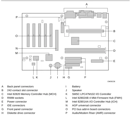
(14) Intel Desktop Board VC820 Technical Product Specification. 1.1.2. VC820 Desktop Board Layout. Figure 1 shows the location of the major components on the VC820 board. A. P. B O C N. D. M. E. L K. J. I. H G. F OM09236. A B C D E F G H. Back panel connectors 242-contact slot connector Intel 82820 Memory Controller Hub (MCH) RIMM sockets Power connector IDE connectors Front panel connector Diskette drive connector. I J K L M N O P. Battery Speaker SMSC LPC47M102 I/O Controller Intel 82802AB 4 Mbit Firmware Hub (FWH) Intel 82801AA I/O Controller Hub (ICH) AGP universal connector PCI bus add-in board connectors Audio/Modem Riser (AMR) connector. Figure 1. VC820 Board Components. 14.
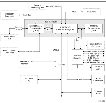
(15) Product Description. 1.1.3. Block Diagram. Figure 2 is a block diagram of the major functional areas of the VC820 board. Primary/ Secondary IDE. ATA33/66 USB. Processor Connector. USB Ports. Host Bus. 820 Chipset 82820 Memory Controller Hub (MCH). Rambus Channel. AHA Bus. 82802AB Firmware Hub (FWH). 82801AA I/O Controller Hub (ICH). RIMM Banks 0, 1. LPC Bus Diskette Drive Connector. AGP Universal Connector. AGP Bus. SMBus LPC I/O Controller. Hardware Monitor. Serial Port A Serial Port B Parallel Port PS/2 Mouse PS/2 Keyboard MIDI/Game Port. PCI Bus Diagnostic LEDs. PCI Slots (5). AC Link. Audio Subsystem. Enhanced Audio. OM08828. Figure 2. Block Diagram. 15.
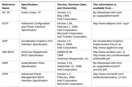
(16) Intel Desktop Board VC820 Technical Product Specification. 1.2 Online Support Find information about Intel desktop boards under “Product Info” or “Customer Support” at these World Wide Web sites: http://www.intel.com/design/motherbd http://support.intel.com/support/motherboards/desktop Find “Processor Data Sheets” or information about “Proper Date Access in Systems with Intel Motherboards” at these World Wide Web sites: http://www.intel.com/design/litcentr http://support.intel.com/support/year2000 Find information about the ICH addressing at this World Wide Web site: http://developer.intel.com/design/chipsets/datashts/. 1.3 Design Specifications Table 2 lists the specifications applicable to the VC820 board. Table 2.. Specifications. Reference Name. Specification Title. Version, Revision Date, and Ownership. The information is available from…. AC ‘97. Audio Codec ‘97. Version 2.1, May 1998, Intel Corporation.. ftp://download.intel.com/ pc-supp/platform/ac97. ACPI. Advanced Configuration and Power Interface Specification. Version 1.0b, February 2, 1999, Intel Corporation, Microsoft Corporation, and Toshiba Corporation.. http://www.teleport.com/~acpi/. AGP. Accelerated Graphics Port Interface Specification. Version 2.0, May 4, 1998, Intel Corporation.. the Accelerated Graphics Implementers Forum at: http://www.agpforum.org/. AMI BIOS. American Megatrends BIOS Specification. AMIBIOS 99, 1999 American Megatrends, Inc.. http://www.amibios.com, or http://www.ami.com/download/ amibios99.pdf. AMR. Audio/Modem Riser Specification. Version 1.01, September 10, 1998, Intel Corporation.. ftp://download.intel.com/ pc-supp/platform/ac97/ amr101.pdf. APM. Advanced Power Management BIOS Interface Specification. Version 1.2, February 1996, Intel Corporation, Microsoft Corporation.. http://www.microsoft.com/ hwdev/busbios/amp_12.htm. continued. 16.
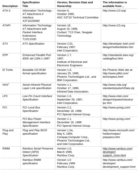
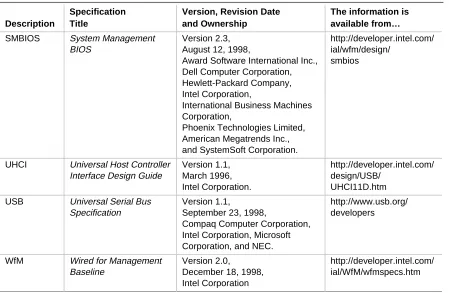
(17) Product Description. Table 2.. Specifications (continued) Specification Title. Version, Revision Date and Ownership. The information is available from…. ATA-3. Information Technology AT Attachment-3 Interface, X3T10/2008D. Version 6, October 1995, ASC X3T10 Technical Committee. http://www.t13.org/. ATAPI. Information Technology AT Attachment with Packet Interface Extensions T13/1153D. Version 18, August 19, 1998, Contact: T13 Chair, Seagate Technology. http://www.t13.org. ATX. ATX Specification. Version 2.01, February 1997, Intel Corporation.. http://developer.intel.com/ design/motherbd/atx.htm. EPP. Enhanced Parallel Port IEEE std 1284.1-1997. Version 1.7, 1997, Institute of Electrical and Electronic Engineers. http://standards.ieee.org/ catalog/bus.html. El Torito. Bootable CD-ROM format specification. Version 1.0, January 25, 1995, Phoenix Technologies Ltd., and IBM Corporation.. the Phoenix Web site at: http://www.ptltd.com/ techs/specs.html. IrDA†. Serial Infrared Physical Layer Link specification. Version 1.1, October 17, 1995, Infrared Data Association.. http://www.irda.org/ standards/pubs/IrData.zip. LPC. Low Pin Count Interface Specification. Version 1.0, September 29, 1997, Intel Corporation.. http://www.intel.com/ design/chipsets/industry/ lpc.htm. PCI. PCI Local Bus Specification. Version 2.2, December 18, 1998, PCI Special Interest Group.. http://www.pcisig.com/. PCI Bus Power Management Interface Specification. Version 1.1, December 18, 1998’ PCI Special Interest Group.. http://www.pcisig.com/. Plug and Play. Plug and Play BIOS specification. Version 1.0a, May 5, 1994, Compaq Computer Corp., Phoenix Technologies Ltd., and Intel Corporation.. http://www.microsoft.com/ hwdev/respec/ pnpspecs.htm. RIMM. Rambus Serial Presence Detect (SPD) Specification. Version 1.0, March 1999, Rambus Corp.. http://www.rambus.com/ developer/ support_rimm.html. Rambus RIMM specification. Version 1.0 February 1999 Rambus Corp.. http://www.rambus.com/ developer/ development_support.html. Description. continued. 17.
(18) Intel Desktop Board VC820 Technical Product Specification. Table 2.. Specification Title. Version, Revision Date and Ownership. The information is available from…. SMBIOS. System Management BIOS. Version 2.3, August 12, 1998, Award Software International Inc., Dell Computer Corporation, Hewlett-Packard Company, Intel Corporation, International Business Machines Corporation, Phoenix Technologies Limited, American Megatrends Inc., and SystemSoft Corporation.. http://developer.intel.com/ ial/wfm/design/ smbios. UHCI. Universal Host Controller Interface Design Guide. Version 1.1, March 1996, Intel Corporation.. http://developer.intel.com/ design/USB/ UHCI11D.htm. USB. Universal Serial Bus Specification. Version 1.1, September 23, 1998, Compaq Computer Corporation, Intel Corporation, Microsoft Corporation, and NEC.. http://www.usb.org/ developers. WfM. Wired for Management Baseline. Version 2.0, December 18, 1998, Intel Corporation. http://developer.intel.com/ ial/WfM/wfmspecs.htm. Description. 18. Specifications (continued).
(19) Product Description. 1.4 Processor CAUTION The VC820 desktop board supports processors that have a 19.3 A maximum current draw (2 V core), or a 22.0 A maximum current draw (1.6 V core). Using a processor not in compliance with these guidelines can damage the processor, the board, and the power supply. See the processor’s data sheet for current usage requirements.. CAUTION Before installing or removing the processor, make sure that AC power has been removed by unplugging the power cord from the computer (the standby power indicator LED should not be lit). Failure to do so could damage the processor and the board. See Figure 6, page 40 for the location of the standby power indicator LED.. ✏. NOTE 66 MHz host bus frequency processors are not supported in this product. A hardware lockout is provided so that if such a processor is installed, the VC820 board will not power-up. The VC820 desktop board supports either a single Pentium III processor at host bus frequencies of 100 or 133 MHz, or a single Pentium II processor at a host bus frequency of 100 MHz. Host bus frequencies for all processors are automatically selected. The VC820 board supports up to 512 KB L2 cache. All supported onboard memory can be cached up to the cachability limit of the processor. See the processor’s data sheet for cachability limits. The VC820 board supports the 242-contact slot type processors listed in Table 3. The processor must be secured by a retention mechanism attached to the board. Table 3.. Supported Processors. Processor Type. Processor Designation (MHz). Host Bus Frequency (MHz). L2 Cache Size (KB). Pentium III processor. 450, 500, 550, and 600. 100. 512. 550E, 600E, 650, and 700. 100. 256. 533B and 600B. 133. 512. 533EB, 600EB, 667, and 733. 133. 256. 350, 400, and 450. 100. 512. Pentium II processor. For information about. Refer to. Processor support for the VC820 boards. Section 1.2, page 16. Processor data sheets. Section 1.2, page 16. 19.
(20) Intel Desktop Board VC820 Technical Product Specification. 1.5 System Memory CAUTION Incorrect insertion of RIMM modules or continuity RIMM modules in the RIMM connectors can damage the VC820 board.. CAUTION Before installing or removing RIMM modules, make sure that AC power has been removed by unplugging the power cord from the computer (the standby power indicator LED should not be lit). Failure to do so could damage the memory and the board. See Figure 6, page 40 for the location of the standby power indicator LED.. 1.5.1. RDRAM Terminology. The VC820 desktop board uses RDRAM technology. For clarity, some RDRAM terms and definitions are included in the list below. • The terms Direct Rambus† and Direct RDRAM are simplified to Rambus and RDRAM. • The Rambus Memory System includes the Memory Controller, which in turn includes the Rambus interface, the Rambus Channel, and the DRAMs with the Rambus interface. • The Rambus Memory Module for desktop systems is referred to as the RIMM module. The RIMM connector supports a RIMM module. • The RIMM module and RIMM connector use a form factor similar to the DIMM module and connector. They do not, however, work interchangeably.. 1.5.2. Memory Features. The Intel 82820 Memory Controller Hub (MCH) integrates a single Rambus channel as an electrically pipelined serial bus (16 data bits in width) with uniform impedance of 28 ohms and single ended termination. This Rambus channel is capable of providing a processor-to-memory bandwidth up to 1.6 GB/sec. The board supports the following memory features: • • • • • •. 20. Up to two 2.5 V, 168-pin, RIMM modules Single- or double-sided RIMM module configurations Serial Presence Detect (SPD) memory only Non-ECC memory with 16-bit components (128 Mbit technology) ECC memory with 18-bit components (144 Mbit technology) 512 MB maximum onboard capacity using 128/144 Mbit technology. For information about. Refer to. The Rambus RIMM Specification. Section 1.3, page 16. The Direct Rambus Serial Presence Detect (SPD) Specification. Section 1.3, page 16.
(21) Product Description. 1.5.3. Continuity RIMM Modules. All RIMM connectors must be populated to achieve continuity for termination at the Rambus interface. Continuity RIMMs (or “pass-through” modules) must be installed in any unused RIMM connectors.. 1.5.4. RDRAM Memory Configuration. CAUTION The board supports combinations of no more than 32 RDRAM components across the installed RIMM modules. If the total number of RDRAM components installed in RIMM connectors exceeds 32, the computer will not boot. Table 4 gives examples of RDRAM component-counts for various RIMM modules. Component counts can be identified on the RIMM label. Table 4.. ✏. Typical RIMM Module Configurations. Rambus Technology. 4 RDRAM components per RIMM. 6 RDRAM components per RIMM. 8 RDRAM components per RIMM. 12 RDRAM components per RIMM. 16 RDRAM components per RIMM. 128/144 Mbit. 64 MB. 96 MB. 128 MB. 192 MB. 256 MB. NOTE To obtain best memory bus loading characteristics, RIMM modules should be installed in Bank 0 first and then in Bank 1. (Bank 0 is closest to the processor.) A Continuity RIMM module must be installed in Bank 1 if unused.. 21.
(22) Intel Desktop Board VC820 Technical Product Specification. 1.5.5. Memory Bus Frequencies. The BIOS automatically selects the memory bus frequency from the Serial Presence Detect (SPD) information in the RIMM module. The VC820 platform supports only Serial Presence Detect (SPD) memory. Serial Presence Detect (SPD) information is required to properly configure the Rambus interface. Table 5 describes the memory frequencies supported with standard configurations of the board. The BIOS configures the Rambus interface to the speed of the slowest RIMM module installed.. ✏. NOTE Intel recommends using only tested memory. For a list of tested memory, see the User-Installable Upgrades Web page at: http://developer.intel.com/design/motherbd/vc/vc_user.htm Table 5.. *. 1.5.6. Memory Bus Frequency with DRCG (Rambus Clock Generator) PC600. PC700. PC800. Host Bus frequency: 100 MHz. 300 MHz. See footnote*. 400 MHz. Host Bus frequency: 133 MHz. 266 MHz. 356 MHz. 400 MHz. The BIOS configures the Rambus interface to a memory bus frequency of 300 MHz for PC700 memory when configured with a host bus speed of 100 MHz. This is equivalent to PC600 performance.. ECC Memory. ECC memory detects multiple-bit errors and corrects single-bit errors. When ECC memory is installed, the BIOS will support both ECC and non-ECC mode. The BIOS automatically detects if ECC memory is installed and provides the Setup option for selecting ECC mode. ECC mode must be enabled in the Setup program; the default setting is disabled. If any non-ECC memory is installed, ECC operation is not available. Table 6 describes the effect of using Setup to put each memory type in each supported mode. Table 6.. ✏. Memory Error Detection Mode Established in Setup Program. Memory Type. ECC Disabled. ECC Enabled. Non-ECC RIMM. No error detection. N/A. ECC RIMM. No error detection. Single-bit error correction, multiple-bit error detection. NOTE Whenever ECC mode is selected in Setup, some performance loss may occur.. 22.
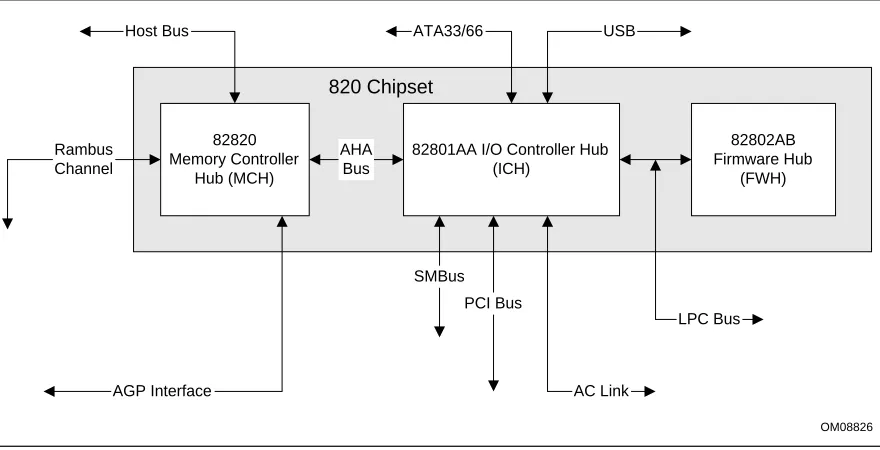
(23) Product Description. 1.6 Intel® 820 Chipset The Intel® 820 chipset consists of the following devices: • 82820 Memory Controller Hub (MCH) with Accelerated Hub Architecture (AHA) bus • 82801AA I/O Controller Hub (ICH) with AHA bus • 82802AB Firmware Hub (FWH) The chipset provides the host, memory, AGP, and I/O interfaces shown in Figure 3.. Host Bus. ATA33/66. USB. 820 Chipset Rambus Channel. 82820 Memory Controller Hub (MCH). AHA Bus. 82801AA I/O Controller Hub (ICH). 82802AB Firmware Hub (FWH). SMBus PCI Bus LPC Bus. AGP Interface. AC Link OM08826. Figure 3. Intel 820 Chipset Block Diagram. For information about. Refer to. The Intel 820 chipset. http://developer.intel.com. The resources used by the chipset. Chapter 2. The chipset’s compliance with ACPI, APM, AC ‘97. Section 1.3, page 16. 23.
(24) Intel Desktop Board VC820 Technical Product Specification. 1.6.1. AGP. The VC820 board supports 1x, 2x, and 4x AGP boards. AGP is a high-performance bus for graphics-intensive applications, such as 3-D applications. AGP, while based on the PCI Local Bus Specification, Rev. 2.1, is independent of the PCI bus and is intended for exclusive use with graphical display devices. AGP overcomes certain limitations of the PCI bus related to handling large amounts of graphics data with the following features: • •. Pipelined memory Read and Write operations that hide memory access latency De-multiplexing of address and data in the bus for nearly 100 percent bus efficiency. For information about. Refer to. Obtaining the Accelerated Graphics Port Interface Specification. Section 1.3, page 16. 1.6.2. USB. The VC820 board has two USB ports; one USB peripheral can be connected to each port. For more than two USB devices, an external hub can be connected to either port. The two USB ports are implemented with stacked back panel connectors. The VC820 board fully supports UHCI and uses UHCI-compatible software drivers. USB features include: • Self-identifying peripherals that can be plugged in while the computer is running • Automatic mapping of function to driver and configuration • Support for isochronous and asynchronous transfer types over the same set of wires • Support for up to 127 physical devices • Guaranteed bandwidth and low latencies appropriate for telephony, audio, and other applications • Error-handling and fault-recovery mechanisms built into the protocol. ✏. NOTE Computer systems that have an unshielded cable attached to a USB port may not meet FCC Class B requirements, even if no device or a low-speed USB device is attached to the cable. Use shielded cable that meets the requirements for full-speed devices.. 24. For information about. Refer to. The location of the USB connectors on the back panel. Figure 8, page 50. The signal names of the USB connectors. Table 18, page 51. The USB specification and UHCI. Section 1.3, page 16.
(25) Product Description. 1.6.3 1.6.3.1. IDE Support IDE Interfaces. The VC820 board has two independent bus-mastering IDE interfaces. These interfaces support: • ATAPI devices (such as CD-ROM drives) • ATA devices using the transfer modes listed in Table 68 on page 103 The BIOS supports logical block addressing (LBA) and extended cylinder head sector (ECHS) translation modes. The drive reports the transfer rate and translation mode to the BIOS. The VC820 board supports laser servo (LS-120) diskette technology through its IDE interfaces. The LS-120 drive can be configured as a boot device by setting the BIOS Setup program’s Boot menu to one of the following: • ARMD-FDD (ATAPI removable media device – floppy disk drive) • ARMD-HDD (ATAPI removable media device – hard disk drive) For information about. Refer to. The location of the IDE connectors. Figure 10, page 57. The signal names of the IDE connectors. Table 31, page 58. BIOS Setup program’s Boot menu. Table 74, page 109. Ultra ATA/66. Section 3.3.2, page 85. 1.6.3.2. SCSI Hard Drive Activity LED Connector. The SCSI hard drive activity LED connector is a 1 x 2-pin connector that allows add-in SCSI controller to use the same LED as the IDE controller. This connector can be attached to the LED output of the add-in controller board. The LED will indicate when data is being read or written using the add-in controller. For information about. Refer to. The location of the SCSI hard drive activity LED connector. Figure 10, page 57. The signal names of the SCSI hard drive activity LED connector. Table 30, page 58. 1.6.4. Real-Time Clock, CMOS SRAM, and Battery. The real-time clock is compatible with DS1287 and MC146818 components. The clock provides a time-of-day clock and a multi-century calendar with alarm features and century rollover. The realtime clock supports 256 bytes of battery-backed CMOS SRAM in two banks that are reserved for BIOS use. A coin-cell battery (CR2032) powers the real-time clock and CMOS memory. When the computer is not plugged into a wall socket, the battery has an estimated life of three years. When the computer is plugged in, the standby current from the power supply extends the life of the battery. The clock is accurate to ± 13 minutes/year at 25 ºC with 3.3 VSB applied. The time, date, and CMOS values can be specified in the BIOS Setup program. The CMOS values can be returned to their defaults by using the BIOS Setup program.. 25.
(26) Intel Desktop Board VC820 Technical Product Specification. ✏. NOTE If the battery and AC power fail, standard defaults, not custom defaults, will be loaded into CMOS RAM at power-on.. ✏. NOTE The recommended method of accessing the date in systems with VC820 boards is indirectly from the Real-Time Clock (RTC) via the BIOS. The BIOS on VC820 boards contains a century checking and maintenance feature. This feature checks the two least significant digits of the year stored in the RTC during each BIOS request (INT 1Ah) to read the date and, if less than 80 (i.e., 1980 is the first year supported by the PC), updates the century byte to 20. This feature enables operating systems and applications using the BIOS date/time services to reliably manipulate the year as a four-digit value. For information about. Refer to. Proper date access in systems with VC820 boards. Paragraph 1.2, page 16. 1.7 I/O Controller The SMSC LPC47M102 I/O Controller provides the following features: • Low pin count (LPC) interface • 3.3V operation • Two serial ports • One parallel port with Extended Capabilities Port (ECP) and Enhanced Parallel Port (EPP) support • Serial IRQ interface compatible with serialized IRQ support for PCI systems • PS/2-style mouse and keyboard interfaces • Interface for one 1.2 MB, 1.44 MB, or 2.88 MB diskette drive • Intelligent power management, including a programmable wake up event interface • PME (Power Management Event) Interface • IrDA† 1.0 compliant • Fan control: Two fan control outputs Two fan tachometer inputs The BIOS Setup program provides configuration options for the I/O controller.. 26. For information about. Refer to. SMSC LPC47M102 I/O controller. http://www.smsc.com.
(27) Product Description. 1.7.1. Serial Ports. The VC820 board has two 9-pin D-Sub serial port connectors located on the back panel. The serial ports’ NS16C550-compatible UARTs support data transfers at speeds up to 115.2 kbits/sec with BIOS support. The serial ports can be assigned as COM1 (3F8h), COM2 (2F8h), COM3 (3E8h), or COM4 (2E8h). For information about. Refer to. The location of the serial port connectors. Figure 8, page 50. The signal names of the serial port connectors. Table 20, page 52. 1.7.2. Infrared Support. On the front panel connector, there are four pins that support Hewlett Packard HSDL-1000 compatible infrared (IR) transmitters and receivers. In the BIOS Setup program, Serial Port B can be directed to a connected IR device. (In this case, the serial port B connector on the back panel cannot be used.) The IR connection can be used to transfer files to or from portable devices like laptops, PDAs, and printers. The Infrared Data Association (IrDA) specification supports data transfers of 115 Kbits/sec at a distance of 1 meter. For information about. Refer to. The infrared port connector. Table 43, page 68. Configuring serial port B for infrared applications. Section 4.4.3, page 100. The IrDA specification. Section 1.3, page 16. 1.7.3. Parallel Port. The connector for the multimode bidirectional parallel port is a 25-pin D-Sub connector located on the back panel. In the BIOS Setup program, the parallel port can be configured for the following: • Output only (PC AT†-compatible mode) • Bi-directional (PS/2 compatible) • EPP • ECP For information about. Refer to. The location of the parallel port connector. Figure 8, page 50. The signal names of the parallel port connector. Table 19, page 52. 27.
(28) Intel Desktop Board VC820 Technical Product Specification. 1.7.4. Diskette Drive Controller. The I/O controller supports one diskette drive that is compatible with the 82077 diskette drive controller and supports both PC-AT and PS/2 modes.. ✏. NOTE The I/O controller also supports a 1.2 MB, 3.5-inch diskette drive. A special driver is required for this configuration however. For information about. Refer to. The location of the diskette drive connector. Figure 10, page 57. The signal names of the diskette drive connector. Table 32, page 59. The supported diskette drive capacities and sizes. Table 69, page 104. 1.7.5. Keyboard and Mouse Interface. PS/2 keyboard and mouse connectors are located on the back panel. The +5 V lines to these connectors are protected with a PolySwitch† circuit that, like a self-healing fuse, reestablishes the connection after an overcurrent condition is removed.. ✏. NOTE The keyboard is supported in the bottom PS/2 connector and the mouse is supported in the top PS/2 connector. Power to the computer should be turned off before a keyboard or mouse is connected or disconnected. The keyboard controller contains the AMI keyboard and mouse controller code, provides the keyboard and mouse control functions, and supports password protection for power-on/reset. A power-on/reset password can be specified in the BIOS Setup program. The keyboard controller also supports the hot-key sequence <Ctrl><Alt><Del> for a software reset. This key sequence resets the computer’s software by jumping to the beginning of the BIOS code and running the power-on self-test (POST).. 28. For information about. Refer to. The location of the keyboard and mouse connectors. Figure 8, page 50. The signal names of the keyboard and mouse connectors. Table 17, page 51.
(29) Product Description. 1.8 Audio The VC820 desktop board offers an enhanced PCI audio system consisting of: • Intel 82801AA I/O Controller Hub (ICH) • AMR connector • Creative Labs’ PCI-128 capable ES1373 digital controller with Crystal Semiconductor CS4297 (A) codec The ICH and AMR support these features: • Split digital/analog architecture for improved S/N (signal-to-noise) ratio: ≥ 85 dB • Power management support for APM 1.2 and ACPI 1.0 (driver dependant) • 3-D stereo enhancement The enhanced PCI audio subsystem has additional features described below.. 1.8.1. Enhanced PCI Audio Subsystem. The VC820 board offers an AC ’97 V 1.03 compliant audio feature-set supported by the Creative Labs ES1373 digital controller with Crystal Semiconductor CS4297 (A) codec (see Figure 4 below). AC ’97 uses a five-wire digital serial interface between the PCI digital controller and the audio codec splitting the digital and analog architecture for improved S/N ratio. This approach supports downloadable wavetables utilizing system memory, eliminating the requirement for a hardware wavetable ROM.. Analog Codec (Crystal Semiconductor CS4297(A)). 82801AA I/O Controller Hub (ICH). AMR Connector. AC ’97 Link. PCI Bus. CD-ROM Line In Audio In Mic In Modem Audio Line Out. AC ’97 Link. Digital Controller (Creative Labs ES1373). Game Port MIDI Interface. OM08843. Figure 4. Block Diagram of AC ’97 V 1.03 Compatible Audio Subsystem with Creative Labs ES1373 Controller and AMR Connector. 29.
(30) Intel Desktop Board VC820 Technical Product Specification. The enhanced PCI audio subsystem supports the following audio connectors: • Audio inputs: Three analog line-level stereo inputs for connection from the back-panel; line in, CD and auxiliary line in One analog line-level input for speakerphone (telephony) •. One mono microphone input Audio outputs: Stereo line-level output Mono output for speakerphone (telephony). The Creative Labs ES1373 digital controller with the Crystal Semiconductor CS4297 (A) codec support the following features: •. •. 30. Creative Labs ES1373 AC ’97 V1.03 Digital Controller: PCI 2.1 compliant PCI bus master for PCI audio 128-voice wavetable synthesizer Aureal A3D† API, Sound Blaster Pro†, Roland MPU-401 MIDI, joystick compatible Ensoniq 3D positional audio and Microsoft DirectSound† 3D support Crystal Semiconductor CS4297 (A) Stereo Audio Codec: High performance 18-bit stereo full-duplex audio codec with up to 48 kHz sampling rate Connects to the ES1373 digital controller using a five-wire digital interface.. For information about. Refer to. Obtaining audio software and utilities. Paragraph 1.2, page 16.
(31) Product Description. 1.8.2. Audio Connectors. The audio connectors include the following: • CD-ROM (legacy-style 2-mm connector) • ATAPI-style connectors: CD-ROM Telephony •. Auxiliary line in Back panel audio connectors: MIDI/Game Port Line out Line in. •. Mic in Audio/Modem Riser (AMR). For information about. Refer to. The back panel audio connectors. Section 2.8.1, page 50. 1.8.2.1. CD-ROM (Legacy-style 2 -mm) Connector. A 1 x 4-pin legacy-style 2-mm connector connects an internal CD-ROM drive to the audio mixer. For information about. Refer to. The location of the legacy-style 2-mm connector. Figure 9, page 55. The signal names of the legacy-style 2 mm connector. Table 25, page 56. 1.8.2.2. ATAPI CD-ROM Audio Connector. A 1 x 4-pin ATAPI-style connector connects an internal ATAPI CD-ROM drive to the audio mixer. For information about. Refer to. The location of the ATAPI CD-ROM connector. Figure 9, page 55. The signal names of the ATAPI CD-ROM connector. Table 26, page 56. 31.
(32) Intel Desktop Board VC820 Technical Product Specification. 1.8.2.3. Telephony Connector. A 1 x 4-pin ATAPI-style connector connects the monoaural audio signals of an internal telephony device to the audio subsystem. A monaural audio-in and audio-out signal interface is necessary for telephony applications such as speakerphones, fax/modems, and answering machines. For information about. Refer to. The location of the telephony connector. Figure 9, page 55. The signal names of the telephony connector. Table 27, page 56. 1.8.2.4. Auxiliary Line In Connector. A 1 x 4-pin ATAPI-style connector connects the left and right channel signals of an internal audio device to the audio subsystem. For information about. Refer to. The location of the auxiliary line in connector. Figure 9, page 55. The signal names of the auxiliary line in connector. Table 28, page 56. 1.8.2.5. Audio/Modem Riser (AMR) Connector. The AMR is a 46-pin riser connector that supports adding modems and/or audio risers to VC820 boards. The AMR interface, utilizing an AC ’97 2.1 link, includes support for audio codec, modem codec, and audio/modem codec devices.. 32. For information about. Refer to. The location of the Audio/Modem Riser connector. Figure 12, page 63. The signal names of the Audio/Modem Riser connector. Table 42, page 66. The AMR specification. Section 1.3, page 16.
(33) Product Description. 1.9 Hardware Management Features The hardware management features enable the VC820 board to be compatible with the Wired for Management (WfM) specification. The VC820 board has several hardware management features, including the following: • Hardware monitor component • Chassis intrusion detection • Fan control and monitoring (implemented on the SMSC LPC47M102 I/O controller) For information about. Refer to. The WfM specification. Table 2, page 16. Fan control functions of the SMSC LPC47M102 I/O controller. Section 1.7, page 26. 1.9.1. Hardware Monitor Component. The hardware monitor component provides low-cost instrumentation capabilities. The features of the component include: • Internal ambient temperature sensing • Remote thermal diode sensing for direct monitoring of processor temperature (if supported in the processor) • Power supply monitoring (+12, +5, +3.3, +2.5, 3.3 VSB, VCCP) to detect levels above or below acceptable values • SMBus interface. 1.9.2. Chassis Intrusion Detect Connector. The VC820 board supports a chassis security feature that detects if the chassis cover is removed. For the chassis intrusion circuit to function, the chassis’ power supply must be connected to AC power. The security feature uses a mechanical switch on the chassis that attaches to the chassis intrusion detect connector. The mechanical switch is closed for normal computer operation. For information about. Refer to. The location of the chassis intrusion detect connector. Figure 11, page 60. The signal names of the chassis intrusion detect connector. Table 39, page 62. 33.
(34) Intel Desktop Board VC820 Technical Product Specification. 1.10 Power Management Features Power management is implemented at several levels, including: • Software support:. •. Advanced Power Management (APM) Advanced Configuration and Power Interface (ACPI) Hardware support: Power connector Fan connectors Wake on LAN technology Instantly Available technology Wake on Ring Resume on Ring Wake from USB Wake from PS/2 keyboard PME# wakeup support. 1.10.1. Software Support. The software support for power management includes: • APM • ACPI If the VC820 board is used with an ACPI-aware operating system, the BIOS can provide ACPI support. Otherwise, it defaults to APM support.. 1.10.1.1. APM. APM makes it possible for the computer to enter an energy-saving standby mode. The standby mode can be initiated in the following ways: • Time-out period specified in the BIOS Setup program • From the operating system, such as the Standby menu item in Windows† 98 In standby mode, the VC820 board can reduce power consumption by spinning down hard drives, and reducing power to, or turning off of, VESA† DPMS-compliant monitors. Power management mode can be enabled or disabled in the BIOS Setup program While in standby mode, the system retains the ability to respond to external interrupts and service requests, such as incoming faxes or network messages. Any keyboard or mouse activity brings the system out of standby mode and immediately restores power to the monitor. The BIOS enables APM by default; but the operating system must support an APM driver for the power management features to work. For example, Windows 98 supports the power management features upon detecting that APM is enabled in the BIOS.. 34.
(35) Product Description. For information about. Refer to. Enabling or disabling power management in the BIOS Setup program. Section 4.6, page 107. The VC820 board’s compliance level with APM. Table 2, page 16. 1.10.1.2. ACPI. ACPI gives the operating system direct control over the power management and Plug and Play functions of a computer. The use of ACPI with the VC820 board requires an operating system that supports ACPI. ACPI features include: • Plug and Play (including bus and device enumeration) and APM support normally contained in the BIOS • Power management control of individual devices, add-in boards (some add-in boards may require an ACPI-aware driver), video displays, and hard disk drives • Methods for achieving less than 30-watt system operation in the power-on/standby sleeping state • A Soft-off feature that enables the operating system to power off the computer • Support for multiple wake up events (see Table 9 on page 37) • Support for a front panel power and sleep mode switch. Table 7 lists the system states based on how long the power switch is pressed, depending on how ACPI is configured with an ACPI-aware operating system. Table 7.. Effects of Pressing the Power Switch. If the system is in this state…. …and the power switch is pressed for…. Off (ACPI G2/S5 – Soft off). Less than four seconds. …the system enters this state Power-on (ACPI G0 – working state). On (ACPI G0 – working state). Less than four seconds. On (ACPI G0 – working state). More than four seconds. Soft-off/Standby (ACPI G1 – sleeping state) Fail safe power-off (ACPI G2/S5 – Soft off). Sleep (ACPI G1–sleeping state). Less than four seconds. Wake up (ACPI G0 – working state). Sleep (ACPI G1–sleeping state). More than four seconds. Power-off (ACPI G2/S5 – Soft off). For information about. Refer to. The VC820 board’s compliance level with ACPI. Section 1.3, page 16. 35.
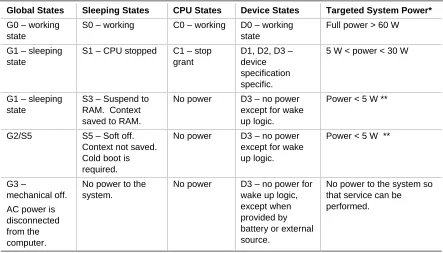
(36) Intel Desktop Board VC820 Technical Product Specification. 1.10.1.2.1. System States and Power States. Under ACPI, the operating system directs all system and device power state transitions. The operating system puts devices in and out of low-power states based on user preferences and knowledge of how devices are being used by applications. Devices that are not being used can be turned off. The operating system uses information from applications and user settings to put the system as a whole into a low-power state. Table 8 lists the power states supported by the VC820 board along with the associated system power targets. See the ACPI specification for a complete description of the various system and power states. Table 8.. Power States and Targeted System Power. Global States. Sleeping States. CPU States. Device States. Targeted System Power*. G0 – working state. S0 – working. C0 – working. D0 – working state. Full power > 60 W. G1 – sleeping state. S1 – CPU stopped. C1 – stop grant. D1, D2, D3 – device specification specific.. 5 W < power < 30 W. G1 – sleeping state. S3 – Suspend to RAM. Context saved to RAM.. No power. D3 – no power except for wake up logic.. Power < 5 W **. G2/S5. S5 – Soft off. Context not saved. Cold boot is required.. No power. D3 – no power except for wake up logic.. Power < 5 W **. G3 – mechanical off.. No power to the system.. No power. D3 – no power for wake up logic, except when provided by battery or external source.. No power to the system so that service can be performed.. AC power is disconnected from the computer.. 36. *. Total system power is dependent on the system configuration, including add-in boards and peripherals powered by the system chassis’ power supply.. **. Dependent on the standby power consumption of wake-up devices used in the system..
(37) Product Description. 1.10.1.2.2. Wake Up Devices and Events. Table 9 lists the devices or specific events that can wake the computer from specific states. Table 9.. Wake Up Devices and Events. These devices/events can wake up the computer…. …from this state. Power switch. S1, S3, S5. RTC alarm. S1, S3, S5. PME# (including PCI 2.2 compliant add-in boards). S1, S3, S5*. LAN (through Wake on LAN technology connector). S5*. Modem (through COM port connector). S1, S3. IR command. S1, S3. USB. S1, S3. PS/2 keyboard. S1, S3. *. S5 with jumper J4A2 pins 1 and 2 connected, see Table 47). 1.10.1.2.3. Plug and Play. In addition to power management, ACPI provides controls and information so that the operating system can facilitate Plug and Play device enumeration and configuration. ACPI is used only to enumerate and configure VC820 board devices that do not have other hardware standards for enumeration and configuration. PCI devices on the VC820 board, for example, are not enumerated by ACPI.. 1.10.2. Hardware Support. CAUTION If the Wake on LAN, Wake from USB and Instantly Available technology features are used, ensure that the power supply provides adequate +5 V standby current. Failure to do so can damage the power supply. The total amount of standby current required depends on the wake devices supported. Refer to Section 2.11.3 on page 75 for additional information. The VC820 board provides several hardware features that support power management, including: • Power connector • Fan connectors • Wake on LAN technology • Instantly Available technology • Wake on Ring • Resume on Ring • Wake from USB • Wake from PS/2 keyboard • PME# wakeup support Both Wake on LAN technology and Instantly Available technology require power from the +5 V standby line. The sections discussing these features describe the incremental standby power requirements for each.. 37.
(38) Intel Desktop Board VC820 Technical Product Specification. Wake on Ring and Resume on Ring enable telephony devices to access the computer when it is in a power-managed state. The method used depends on the type of telephony device (external or internal) and the power management mode being used (APM or ACPI).. ✏. NOTE The use of Wake on Ring, Wake from USB, and Resume on Ring technologies from an ACPI state requires an operating system that provides full ACPI support.. 1.10.2.1. Power Connector. When used with an ATX-compliant power supply that supports remote power-on/ -off, the VC820 board can turn off the system power through software control. To enable soft-off control in software, power management must be enabled in the BIOS Setup program and in the operating system. When the system BIOS receives the correct APM command from the operating system, the BIOS turns off power to the computer. With soft-off enabled, if power to the computer is interrupted by a power outage or a disconnected power cord, when power resumes, the computer returns to the power state it was in before power was interrupted (on or off). For information about. Refer to. The location of the power connector. Figure 11, page 60. The signal names of the power connector. Table 35, page 61. The ATX specification. Section 1.3, page 16. 1.10.2.2. Fan Connectors. The VC820 board has three fan connectors. The functions of these connectors are described in Table 10. Table 10.. Fan Connector Descriptions. Connector. Function. System fan (Fan 1). Provides +12 V DC for a system or chassis fan. The fan voltage can be switched on or off, depending on the power management state of the computer. A tachometer feedback connection is also provided.. Power supply fan control (Fan 2). Provides +12 V DC for a system or chassis fan. The fan voltage can be switched on or off, depending on the power management state of the computer. A tachometer feedback connection is also provided.. Processor fan (Fan 3). Provides +12 V DC for a processor fan or active fan heatsink. For information about. 38. Refer to. The location of the fan connectors. Figure 11, page 60. The signal names of the fan connectors. Section 2.8.2.3, page 60.
(39) Product Description. 1.10.2.3. Wake on LAN Technology. CAUTION For Wake on LAN technology, the 5-V standby line for the power supply must be capable of providing adequate +5 V standby current. Failure to provide adequate standby current when implementing Wake on LAN technology can damage the power supply. Refer to Section 2.11.3 on page 75 for additional information. Wake on LAN technology enables remote wakeup of the computer through a network. The LAN subsystem PCI bus network adapter monitors network traffic at the Media Independent Interface. Upon detecting a Magic Packet† frame, the LAN subsystem asserts a wakeup signal that powers up the computer. Depending on the LAN implementation, the VC820 board supports Wake on LAN technology in one of two ways: • Through the Wake on LAN technology connector (APM or ACPI S5 only) • Through the PCI bus PME# signal (for PCI 2.2 compliant LAN designs) The Wake on LAN technology connector can be used with PCI bus network adapters that have a remote wake up connector, as shown in Figure 5. Network adapters that are PCI 2.2 compliant assert the wakeup signal through the PCI bus signal PME# (pin A19 on the PCI bus connectors).. Network Interface Card. Remote Wake up connector. Wake on LAN technology connector. PCI Slot. Desktop Board OM09129. Figure 5. Using the Wake on LAN Technology Connector For information about. Refer to. The location of the Wake on LAN technology connector. Figure 11, page 60. The signal names of the Wake on LAN technology connector. Table 37, page 62. 39.
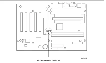
(40) Intel Desktop Board VC820 Technical Product Specification. 1.10.2.4. Instantly Available Technology. CAUTION For Instantly Available Technology, the 5-V standby line for the power supply must be capable of providing adequate +5 V standby current. Failure to provide adequate standby current when implementing Instantly Available technology can damage the power supply. Refer to Section 2.11.3 on page 75 for additional information. Instantly Available technology enables the VC820 board to enter the ACPI S3 (Suspend-to-RAM) sleep-state. While in the S3 sleep-state, the computer will appear to be off (the power supply is off, the fans are off, and the front panel LED is amber if dual-color, or off if single-color.) When signaled by a wake-up device or event, the system quickly returns to its last known wake state. Table 9 on page 37 lists the devices and events that can wake the computer from the S3 state. The VC820 board supports the PCI Bus Power Management Interface Specification. For information on the versions of this specification, see Section 1.3. Add-in boards that also support this specification can participate in power management and can be used to wake the computer. The use of Instantly Available technology requires operating system support and PCI 2.2 compliant add-in boards and drivers. The standby power indicator LED (located between the AGP universal connector and the RIMM Bank 0 connector) provides an indication that power is still present to the RIMM modules and PCI bus connectors, even when the computer appears to be off. Figure 6 shows the location of the standby power indicator LED.. DS6F1. OM09237. Standby Power Indicator. Figure 6. Location of Standby Power Indicator LED. 40.
Figure
+7

Related documents
An ini- tial, gas-phase-only version of this model, the Atmospheric Chemistry and Canopy Exchange Simulation System (AC- CESS), includes processes accounting for the emission of
As far as we know, all current optimized flow routing strategies can schedule only large flows, since it is far from trivial to schedule each of the numerous short,
[r]
Using the SMS attributes specified in the management class and storage group provides space and availability management at the data set and volume level.. Figure 1-2 shows the
Along pre-apical and apical zones a zoomed view of file progression in the canal is shown on the enlarged root image on the right side of the display (Apical Zoom), and
- Check in point 2 located directly outside airport, for Shuttle Wristband Exchange and Trogir/Seget Apartment/ Kasteli Apartment check in. - Direct coach to Beachville Campsite
REACH YOUR WINTER SPORTS ENTHUSIASTS TARGET GROUP, WITH OUR INNOVATIVE ADVERTISING POSSIBILITIES.. WE PLAN YOUR CAMPAIGN - ACCORDING TO YOUR PERSONAL WISHES
Poor household energy efficiency, increasing electricity costs, and overcrowding are identified as key other causal factors of energy poverty (The Guardian, 2016). In such context,
