A representation scheme for digital product service system definitions
Alison McKay
⇑, Saikat Kundu
1School of Mechanical Engineering, University of Leeds, Leeds LS2 9JT, UK
a r t i c l e
i n f o
Article history:
Received 21 August 2012
Received in revised form 9 July 2014 Accepted 11 July 2014
Available online 14 August 2014
Keywords: Service definition
Product service systems (PSS) PSS representation
PSS development
Computer-aided engineering
a b s t r a c t
The growing trend for delivering physical products to customers as parts of product service systems (PSS) is creating a need for a new generation of Computer Aided Design (CAD) system to support the design of PSS: so-called ‘‘PSS-CAD’’. Key research issues in the development of such systems include building understanding of the kinds of applications that designers of PSS might need and the establishment of well-founded representation schemes to underpin and support communication between PSS-CAD systems. Recent literature includes numerous descriptions of integrated PSS development processes, PSS-CAD tools to support these processes and early meta-models to provide information support. This paper complements this work by proposing a representation scheme that is a key prerequisite to achiev-ing the interoperability between PSS-CAD systems which would be necessary to support the deployment of integrated PSS development processes in industry.
The representation scheme, a form of meta-model, draws on learning from the product definition community that emerged in the 1970s in response to a need for interoperability between the different shape-based CAD systems that were being developed at the time. The initial focus on shape representa-tion has developed to digital product definirepresenta-tions that define the design of a product coupled with meta-data recording details of processes by which the design was created and, more recently, supported through-life. Similarly, PSS-related information includes both PSS definitions, to support the lifecycles of physical products and associated services, and meta-data needed to support the management of PSS development processes.
This paper focuses on information requirements for the definition of service elements of PSS and rela-tionships with product elements and service actors. These requirements are derived from earlier work on the use of service blueprinting for the visualisation and mapping of service activities to deliver different types of service contract. Key information requirements addressed include the need to represent service process flow and breakdown structures, relationships between service and product elements, substitu-tion relasubstitu-tionships, and service variants. A representasubstitu-tion scheme is proposed and demonstrated through application to a PSS case study. The representation scheme is built on a generic information architecture that has already been applied to problems of product definition; as such there is an underlying compat-ibility that offers real promise in the future realisation of integrated PSS development processes.
Ó2014 The Authors. Published by Elsevier Ltd. This is an open access article under the CC BY license (http://creativecommons.org/licenses/by/3.0/).
1. Introduction
The transition from the delivery of products to product service systems (PSS) is driving companies to focus on the performance of not only the products they develop and deliver to customers but also the services used to provide through-life support for these products. A consequence of this transition is that the role of the
physical product is changing. Where once the development of products was a goal in its own right, increasingly products are parts of PSSs where the goal is to support and operate products through their lifecycles. This has led to an increasing interest in both the integration of products and services[64]and innovation in service offerings [37,53]. In response, the description of inte-grated service development processes is growing [20,30,47,59] and the need to consider both product and service lifecycles, and interactions between them, early in PSS development processes when the cost of change is at its lowest, is increasingly recognised [31,72]. In their broadest sense, PSS-CAD systems will support PSS developers in understanding these issues and many authors describe service design and development tools[23,51].
http://dx.doi.org/10.1016/j.aei.2014.07.004
1474-0346/Ó2014 The Authors. Published by Elsevier Ltd.
This is an open access article under the CC BY license (http://creativecommons.org/licenses/by/3.0/). ⇑ Corresponding author. Tel.: +44 113 343 2113.
E-mail addresses: [email protected] (A. McKay), [email protected] (S. Kundu).
1
Present address: School of Engineering, Manchester Metropolitan University, ll Saints Building, All Saints, Manchester M15 6BH, UK. Tel.: +44 161 2471636.
Contents lists available atScienceDirect
Advanced Engineering Informatics
Like product development processes, integrated PSS develop-ment processes will require underlying information architectures through which the integration of these tools can be achieved. A key to the realisation of such architectures lies in the establish-ment of well-founded representation schemes to support the defi-nition of PSS through their lifecycles. This paper introduces such a representation scheme for service elements of PSS. It has been val-idated through application to case studies on the definition of con-tracted services in high value manufacturing systems [34]. The resulting digital service definitions have been used to support risk management of an industrial service[35]and the articulation of information requirements in the defence sector[14]. In the future such definitions could increase the use of computer-based evalua-tions of service concepts, for example by integrating them with simulation models[15], and more human-centred service design activities such as those discussed by Meiren et al.[47].
The representation scheme draws on learning from product def-inition both on the kinds of functionalities that might be required in PSS development processes and how such information might be represented. Parallels between the definition of product and ser-vice elements of PSS are introduced in Section 2.1 and used to inform requirements for digital service definition. The model has been implemented to support the definition of a range of industrial services that are subject to confidentiality restrictions. For this rea-son, a fragment of a fictitious case study that exhibits key charac-teristics of these real-world PSS, a coffee making machine repair service with two types of contract (spares only and availability [71]), is introduced in Section 3. The representation scheme, in the form of an information model, is introduced in Section4and its efficacy demonstrated through application to the coffee maker case study through population (in Section4) and through imple-mentation in a prototypical PSS definition system (in Section5). An analysis of its efficacy in comparison to PSS meta-models avail-able in the literature is provided in Section6and areas for further research are outlined in Section7.
2. Literature review
Information requirements used to inform the development of product data representation schemes result from analyses of (i) the kinds of information that need to be captured to support prod-uct-related engineering processes and (ii) the kinds of tools and techniques the representation scheme is required to support. This section provides information requirements for the representation of service elements of PSS (Section 2.3) based on reviews of approaches to the definition of service products when compared with physical products (Section2.1), and tools and techniques used for the definition of services (Section2.2).
2.1. Definitions of physical products and service products
For the purpose of this paper, a PSS is a system composed of a physical product and associated services that support the product through-life. Thinking on the dual nature of technical artefacts argues that technical artefacts have both designed physical struc-tures and intended functional strucstruc-tures. On intended functional structures, Vermaas and Houkes, in their ICE (Intentionalist, Cau-sal-role, Evolutionist) theory [74], assert that when engineers ascribe functions to artefacts they have to consider explicitly the goals for which agents use artefacts and the actions that constitute their use; the agents’ actions are captured in a ‘‘use plan’’. A num-ber of papers resulting from this work, for example[33], include discussions on the distinction between function, behaviour and capacity of physical artefacts. Mumford[49]provides the following definitions for function and capacity: capacity is a property of an
artefact that is understood according to what it can do or what function it can play in relation to other properties; function is a capacity plus the use plan that exploits it for an intended purpose. In this paper we take the view that, in a given PSS, the service elements are forms of use plan for the product elements.
On designed physical structures, Simons[61]uses mereology to provide a theoretical basis for the definition of physical product structures, of which bills of materials are a common manifestation. Key elements for a physical product definition are geometry, mate-rial specification and process plan. Design rationale, as captured using tools such as Rationale™[5,55,73]and DRed[11], is a means by which designed physical structures are related to intended functional structures. Design intent, for example as captured using
advanced requirements management techniques [2], enables
intended functional structures to be related to stakeholder intents and so aspects of what Vermaas and Houkes refer to as use plans. An initial analysis of requirements for the definition of physical products and services is provided inTable 1.
It can be seen that there are alignments in the lifecycle stages of products and services and potential commonality in the represen-tation schemes that might be used to represent requirements and design rationale. A key difference is that a core aspect of a physical product definition is its shape whereas the core aspect of a service definition is the service delivery process. There are many approaches to the definition of processes in the literature and some include digital process definitions that are used to support process evaluations. For example, Wynn et al.[76]report work related to the definition and simulation of product development processes. However, the underlying representation schemes for these process definitions are typically not published and, for this reason, the extent to which they might be integrated into PSS definitions is uncertain.
2.2. Service definition tools and techniques
A number of tools and techniques are being developed to support the definition of services in the fields of social and behav-ioural sciences, business, design and information technology; for the range of information to be supported see[69]and for examples of the tools and techniques see[19]. Tassi[65]presents a collection of these tools and techniques according to the following categories:
(i) the design activities they support (e.g. envisioning, design-ing/co-designing, testing and prototyping);
(ii) the kind of representation they produce (e.g. text, graphs, narratives, models, games);
(iii) the recipients they address (e.g. stakeholders, professionals, service staff, users); and
(iv) the contents of the project they convey (e.g. context, system, offering, interaction).
results in a modified service blueprint that includes a blend of product and service structure elements.
The two most widely reported PSS-CAD systems are ‘‘Service CAD’’ [58] and ‘‘Service Explorer’’ [23]. Cavalieri and Pezzotta [13]refer to a PSS engineering process which can be regarded as a core business process within which PSS design, along with other activities, sits. Cavalieri and Pezzotta highlight the importance of creating PSS whose lifecycle processes are considered in a system-atic way during the design process. Many research groups report developments of such systems[57]. As with the development of product CAD in the 1980s, the reporting of these systems tends to focus on system functionality rather than the underlying repre-sentation schemes on which the systems are built. However, an analysis of the system outputs presented in these papers highlights a need for the representation of both functional and service activity structures and, in each kind of structure, both part-whole and con-nection relationships. For example, the representation of Hara et al.’s PSS function structure[23]requires a functional part-whole structure whereas their behaviour blueprint would require a func-tional structure with connection relationships, and their activity blueprint a service activity structure with connection relation-ships. Similarly, for the representation of PSS to support Sakao et al.’s system[58], the outputs presented include service function structures, service flow structures, product breakdown structures and relationships between elements of product and service structures.
Other PSS-CAD researchers focus on supporting later stages of PSS design and development processes. For example, ‘‘Service Explorer’’ and ‘‘Service CAD’’ both include means of visualising ser-vice activities. Visualisation draws information from the system’s underlying representation of a service and presents it in ways that are useful to system users. In addition to supporting visualizations by people, CAD systems also provide information to support appli-cation packages such as, for product-CAD, engineering analysis. Rese et al. [56] recognise the different needs of individual user groups and propose a framework for the definition of information strategies that are sensitive to these needs. Dill and Schendel[17] propose an approach to PSS design that supports the generation and evaluation of PSS alternatives; the generated variants are rep-resented using a simplified version of a service blueprint where activities are positioned within swim lanes but not connected to each other flow-wise. This supports evaluation of variants based on ownership and transaction costs. Service simulation can also be regarded as a form of service system application. Cuthbert et al.[15], for example, describe an application of discrete event simulation to maintenance services. Supporting such applications
requires a service representation that includes both service and product related aspects of the PSS.
The representation scheme introduced in this paper supports the definition of product and service elements of PSS and both part-whole and connection relationships between them. In addition, it has the flexibility to support Dill and Schendel’s system because process/activity steps can be defined without ships between them – this is because both elements and relation-ships are treated as first class objects. As a result the representation scheme could be used to underpin the exchange and sharing of data between users of the two systems. From the available litera-ture, the ‘‘Service Explorer’’ and ‘‘Service CAD’’ systems each supports detailed PSS definitions at a single point in time. When used in live PSS engineering processes, there will also be a need to support how PSS definitions change over time and in response to the needs of individual customers. The representation scheme in this paper can be used to support this additional information through substitution relationships and the definition of PSS variants (see Sections4.4 and 4.5).
2.3. The definition of service information
[image:3.595.44.563.88.257.2]Zeithaml et al.[77]identify five quality gaps in service delivery that may result in service failure. Managerial strategies to close the service quality gaps are recommended by Zeithaml et al. and distilled by Lovelock and Wirtz[38]. Several are related to improv-ing the management of service information. Effective delivery of service demands access to high quality service information (i.e. complete, correct, minimal and available to the right people at the right time). McFarlane [40] asserts that the information requirements for support service solutions are multifaceted and highly dependent on the nature of the offering and the underpin-ning service agreement. Berkeley and Gupta[9]survey information required to deliver quality services involving high levels of cus-tomer contact. In high cuscus-tomer contact services, a firm’s ability to deliver a quality service depends on its capacity to collect, pro-cess, distribute and use information. According to Berkeley and Gupta, service delivery processes can be broken down into three broad categories: input information, process information and out-put information. The representation scheme introduced in this paper defines the service itself; this service definition could include the definition of service processes that collect and operate on data in all three of Berkeley and Gupta’s categories. In this context, a number of researchers propose ways of representing services although the focus is on service concepts rather than the service definition itself; these systems support early stages of PSS design Table 1
Initial analysis of requirements for the definition of physical products and services.
Product (artefact–goods) definition Product (service) definition parallels
Product Specification:Requirements and links to stakeholder needs[2] For services, Service Level Agreements, Performance Indicators (PIs) and Key Performance Indicators (KPIs) constitute a service specification
Product Definition:What is defined depends upon the kind of product and the product development process being used: specifically, the information required at each stage gate and through key process steps
Service designs (including ‘‘to be’’ service processes) are equivalent to product definitions. Drawing parallels with physical product development, understanding of the Service Development Process, for example ABB Full ServiceÒ[1], which provides process phases and decision points is needed to determine the scope and coverage of service definitions
Product Definition/Representation:Product structure and relationships are key information[44]. Product definitions include shape and material
Service definitions include process definitions and structures. Services have no physical shape or material specifications; research identifying key properties of service products is in its early stages
and development processes. Becker et al.[8]provide a review of these approaches. Given their focus, it is not surprising that the representation schemes within such systems tend to support the definition of service concepts and requirements. Welp et al.[75] propose three planes (function, process and object) which must be addressed through service representation schemes. The repre-sentation scheme introduced in this paper sits on Welp et al.’s process plane.
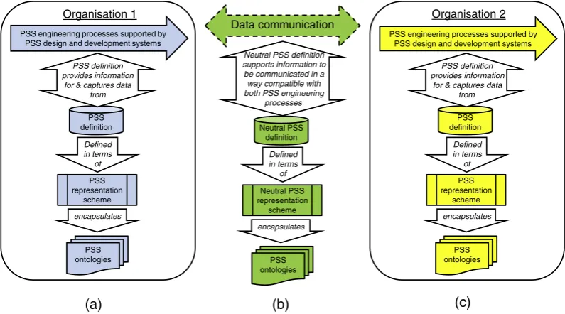
Each of the papers reviewed in the previous paragraph supports the positioning of PSS representation schemes with respect to both their scope and level of detail. In discussing more detailed aspects of PSS knowledge and information management, the literature refers to a range of knowledge and information models, ontologies and languages. Fig. 1provides a framework that is used in this paper to create a coherent overview of these PSS knowledge and information management solutions. The figure provides a sche-matic that shows the underlying information infrastructure needed to support knowledge intensive activities such as PSS engineering. It can be seen that each organisation (which could be different functions within one company or separate companies in a supply network) has a different manifestation (indicated by the different colours used in the figure) of a PSS engineering pro-cess. Each PSS engineering process interacts with (taking informa-tion from and adding informainforma-tion to) its own PSS definiinforma-tion. In turn, each of these definitions is defined in terms of a PSS represen-tation scheme which will be tailored to suit the needs of the engi-neering process it is intended to support. These representation schemes can be viewed using the ANSI/SPARC three layer model for database management systems[16]. This model includes three perspectives for considering database schemas: multiple external views which address the needs of specific applications and users, a single conceptual view which includes information structures that support all of the external views, and one or more internal (or physical) views which specify how the conceptual view is implemented on different computational platforms and/or using different implementation methods. Finally, each representation scheme is underpinned by one or more ontologies which specify the concepts and relationships captured through the representa-tion scheme. The central secrepresenta-tion ofFig. 1, labelled (b), shows a sim-ilar structure for supporting communication of PSS definition data between the organisations represented in sections (a) and (c) of the
figure. It can be seen that the underlying infrastructure has a com-mon structure but different manifestations to either of the two organisations; this is because the purpose of the central portion (to support communication) is different to the purpose of the other two sections (to support the engineering of PSS offerings).
PSS definition data is generated and used through PSS engineer-ing processes. Maussang et al.[39]describe a PSS design method-ology that encompasses both service and product structures. A core aspect of the theoretical basis upon which the service definitions of this methodology build lies in process definition and modelling. For example, Maussang et al. show connections between service and product breakdown structures and Stanicek and Winkler[62] report an application of conceptual modelling to the behaviour of a service system. The representation scheme in this paper enables the definition of multiple service breakdown structures of a given service. The nature of these [PSS lifecycle] processes determines the information content (both scope and level of detail) in the PSS definition and, therefore, the necessary representation schemes and underlying theoretical frameworks and ontologies. Hepperle et al.[24]define a PSS lifecycle model that includes key PSS lifecycle activities connected to a process model. This model is equivalent to an Application Activity Model in a STEP Application Protocol[25]and could be used to identify PSS engineering activ-ities and information flows that are in (and out of) scope for the underlying information system. Hepperle et al.’s model could be coupled with Muller et al.’s[48]framework for the elicitation of PSS requirements to create information requirements for the PSS definition needed to support particular PSS lifecycle activities. In this vein, Goh et al.[22]give an example of how in-service data collected through the delivery of a PSS might be made available to inform future design activities.
The implementation and population of representation schemes with sample data is a widely accepted means of validating repre-sentation schemes. For example, in the STEP standard, Abstract Test Cases are used to provide such data. Such test cases, in their development, can be used to validate the underlying representa-tion schemes and, in use, can be used to test software tools that implement the representation schemes. Ontologies can be tested in the same way, either through implementation and use in knowl-edge engineering systems such as Protégé or through implementa-tion in data models that can be populated using methods similar to
Defined in terms
of PSS definition Organisation 1
PSS engineering processes supported by PSS design and development systems
PSS definition provides information
for & captures data from
PSS representation
scheme
encapsulates
PSS ontologies
Data communication
PSS definition Organisation 2
PSS engineering processes supported by PSS design and development systems
PSS representation
scheme
encapsulates
PSS ontologies Neutral PSS
definition Neutral PSS definition supports information to be communicated in a way compatible with both PSS engineering
processes
Neutral PSS representation
scheme
PSS ontologies
PSS definition provides information
for & captures data from
Defined in terms
of Defined
in terms of
encapsulates
[image:4.595.92.490.519.740.2](a)
(b)
(c)
those used in this paper. A number of authors introduce ontologies that could be used to underpin PSS knowledge and information management systems. However, from information available in the literature, these are in the very early stages of development and require substantial verification and validation efforts before being translated into wide practice. For example, Annamalai et al. [4]present an ontology that was developed through engagement with a wide PSS community and contains a potentially useful col-lection of attributes for PSS definitions but without detail on how such attributes, or PSS definitions more generally, might be defined and structured for specific purposes derived from PSS engineering process needs. Annamalai et al. cite Bullinger et al.[12]who intro-duce a service model (a representation scheme in the terminology ofFig. 1) where service activities are defined as parts of service structures which include flow, composition, alternative, substitu-tion and integrasubstitu-tion relasubstitu-tionships. Bullinger et al.’s model repre-sents these relationships as attributes of service activities in contrast to the representation scheme introduced in this paper which supports the explicit definition of these kinds of relationship and, because the relationships are treated as first class objects, the addition of attributes and relationships to other PSS elements. More details on the implications of this are given in Section6. Sim-ilarly, Doultinsou et al.[18]present a UML model for the capture of service information for use in engineering design and Zhu et al. [79] provide an ontology for maintenance, repair and overhaul services. Like Annamalai et al., both of these models have been developed using systematic processes, and screenshots from early implementations are provided, but neither paper provides detail of how the models have been validated or might be used in engineer-ing processes such as design (Doultinsou et al.) or maintenance, repair and overhaul (Zhu et al.). Hara et al.[23]highlight different types of PSS structure and their importance in the configuration of PSS offerings. Two key service structures are shown in Service Explorer screenshots and highlighted in their behavioural and activity blueprints. The representation scheme introduced in this paper could be used to define these different kinds of structure and, because they use the same underlying structure as product definitions, these definitions could be explicitly related to elements of product structures which are represented as hardware entities in the Service Explorer system.
3. Case study – Coffee maker machine maintenance and repair service
PSS definitions are typically not presented in the literature because of commercial sensitivities. This is comparable to product-related literature where, again, design details are rarely published. In such situations, researchers tend to use synthetic case studies that reflect key characteristics of the PSS they are working with. For example, Kim et al.[28]use a case study based on the laundry industry. The efficacy of the representation scheme presented in this paper is demonstrated by populating it with data from a case study based on maintenance services that draw on examples from the high value manufacturing sector but, for confi-dentiality reasons, using a fictitious coffee making machine PSS. The representation scheme introduced in this paper has been used to capture service blueprint information in the form of digital ser-vice definitions. In this paper it is applied to a fragment of the cof-fee maker machine maintenance and repair service case study introduced in[45]. A labelled fragment of this case study, used in this paper, is given inFig. 2.
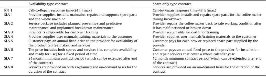
The whole case study defines a service for two types of contract: availability and spares only. For the availability type contract, the coffee maker manufacturer supplies coffee maker machines to its customer and takes responsibility for their maintenance and repair
in an availability type contract. The service level agreements (SLAs) and key performance indicators (KPIs) for the availability type con-tact are shown in the middle column of Table 2. On the other hand, in the spares only type contract, the coffee maker manufac-turer supplies coffee maker machines to its customer and takes responsibility for their installation and repair in the event of break-down in a spare only type contract. The service level agreements and key performance indicators for the spares only type contact are outlined in the right-hand column ofTable 2.
The key process steps carried out in the coffee maker machine maintenance and repair service for both availability and spares only type contracts are illustrated in the flow chart inFig. 2. The process steps carried out only in availability type service contracts are shown by the hatched shapes and the process steps carried out only in the spares only type service contract are shown by shapes filled with dots. Substitute or alternate process steps in both types of contract are tagged usingSxandAxrespectively. For example, the
process step tagged withS1is used in the spares only type contract and is replaced by the process step tagged withA1in availability type contracts. Process steps carried out by the service provider are represented by shapes with solid outlines whilst those done by the service customer are shown using shapes with dashed out-lines. The process steps are logically connected by solid arrows to represent the process sequence. The process flow is in the arrow direction. The dashed arrows represent flow of physical artefacts during service delivery. Other labels in this figure are used for clarification later in the paper.
4. Underlying information model and its application to the case study
An information model for the definition of PSS structures is given inFig. 3. It is an adapted version of the general model for product, process and supply network structures which was originally pre-sented in[42]. The model is based on a theoretical foundation that combines mereology with learning that has evolved from work on the definition of product structure models through process struc-ture to supply chain and enterprise network models. A key feastruc-ture is that elements and relationships (nodes & arcs) are treated equally, as first class objects, and, as a result, each can exist inde-pendently of the other. This capability is exploited in this paper to represent PSS. The model in Fig. 3 is described in this section through application to the case study introduced in Section3.
The information model shown in Fig. 3 is drawn using the EXPRESS-G notation ([25]). EXPRESSis used because the representation
scheme presented in this paper is a conceptual model (in an ANSI/ SPARC sense) and, therefore, not directly related to a specific implementation form or method; the STEP standard provides a ser-ies of standards (ISO-10303:20 serser-ies) which specify how EXPRESS
data specifications might be translated into a range of implemen-tation methods. In addition, the represenimplemen-tation scheme introduced in this paper is validated through population using a graphical notation of EXPRESS-I[27], EXPRESS-I-G, that allows instance data to
be presented with explicit reference to constructs (entities and relationships) in the underlying data model. Most of the ontologies and representation schemes reviewed in Section3are defined and implemented using object oriented approaches (forms of internal schema in an ANSI/SPARC sense). Zhao and Liu[78]give an exam-ple of the translation of an EXPRESSdata specification into the OWL
Web Ontology Language. The boxes in Fig. 3represent concepts (EXPRESS entities) and the lines represent relationships between
plain end. For example, everystructured_element_relationshiphas two and only two structured_elements and, every structured_ele-mentcan play the role of zero, one or manyrelatingandrelated structured_element_relationships. The heavy lines represent special-isation relationships. For example, inFig. 3 a structured_element can be either anitemor anitem_relationshipand a givenitemis either apart, aprocess_step, aninformation_requirement, aphysical artefact oradecision2. It can also be seen that a given item_relation-shipcan represent either acompositionor aconnectionrelationship. The remainder of this section reports the application of this information model to represent key facets of service elements of the PSS case study introduced in Section3.
4.1. Definition of service process flow structures
A service process flow structure is a collection of process steps (shown by rectangles and diamonds inFig. 2) and the connections
between them that are needed to deliver the service (shown by solid arrows inFig. 2). With respect to product definitions, and tak-ing a view that, like physical products, services have lifecycles, the service flow structure in the case study can be regarded as an as-designed service definition. An instance of the information model given in Fig. 3, for the part of the service definition given in Fig. 2, is shown inFig. 4. It can be seen that three process steps (labelled with black stars) are shown. Each is defined as aprocess stepwhich is a subtype ofitem, and each flow between process steps (V, W and XA) is represented using the connection entity
which is a subtype of theitem relationshipentity. The EXPRESS-I-G
also includes an information requirement (labelled with an open star) which, like process steps, is modelled as a subtype of theitem entity and can therefore be connected to process steps in the same way as process steps are connected to each other. This flexibility, in a relatively small information model, results primarily from both elements and relationships being treated as first class objects.
A key reason for developing the representation scheme intro-duced in this paper was to support the creation of digital service blueprints. A service blueprint is built around the principal stages Report
problem & schedule engineer’s
visit
Visit customer, take charge of faulty product, and diagnose problem & root
cause Handover product to engineer
Identify repair & maintenance requirements
Need any spare parts? Identify spare
parts requirements
Source spare parts from suppliers & send to service
engineer
Spare parts Yes
Availability info. of service engineer &
customer
KEY:
Service provider process step
Service customer process step
Decision
Process step jointly
done by provider &
customer Key information requirement
Physical artefact
X substitute process for availability
Agreed maintenance schedules from
planning DB th
contract
Process step done only in availability type contract
Identify repair requirements
Xthsubstitute process for spare
[image:6.595.106.477.71.298.2]only contract
[image:6.595.33.553.376.527.2]Fig. 2.Labelled fragment of service to demonstrate the capability of the information model introduced in this paper. Adapted from[45]
Table 2
Service level agreements (SLAs) and key performance indicators (KPIs) for availability type and spare only type contracts for coffee maker machine’s maintenance and repair service.
Availability type contract Spare only type contract
KPI 1 Call-to-Repair response time-24 h (max) Call-to-Repair response time-48 h (max)
SLA 1 Provider supplies, installs, maintains, repairs and supports spare parts and the whole machine
Provider supplies, installs and repairs spare parts for the coffee maker during breakdown
SLA 2 Service package includes planned preventive and predictive maintenance, and unplanned breakdown maintenance
Provider repairs the coffee maker back to safe working condition after it has malfunctioned or broken down
SLA 3 Provider is responsible for customer training Provider responsible for customer training
SLA 4 Provider supplies user manuals/training materials to the customer Provider supplies user manuals/training materials to the customer SLA 5 Customer pays an annual fixed price to the provider for availability of
the product (coffee maker) and services
Customer pays for each new or replaced spare part supplied by the provider
SLA 6 The price includes both spares and services (i.e. complete availability and ready for use) for a fixed period of time
Customer pays an annual fixed price to the provider for installation and repair services that cover a whole calendar year
SLA 7 24 month minimum contract period (which can be extended after end of the contract)
12 month minimum contract period (which can be extended after end of the contract)
SLA 8 Services are provided on both as-planned and on-demand bases for the duration of the contract
Services are provided on an on-demand basis for the duration of the contract
2
(i.e. key process steps) of the service and two axes on the blueprint: (i) a horizontal axis representing the chronology of actions conducted by the service customer and the service provider and (ii) a vertical axis that distinguishes between different areas of actions – these areas of actions are separated by different lines of visibility and interaction. The information represented in Fig. 4 supports the positioning of service process steps on the horizontal axis of a service blueprint.
4.2. Identification of who carries out each process step
For the vertical axis of a service blueprint, two kinds of process need to be captured: principal actions and support processes. Principal actions can be of three types: onstage principal actions by the customer, and onstage and backstage principal actions by
the service provider’s customer contact personnel. A service pro-vider’s principal actions and support processes interact with IT resources. For technical services these could include engineering information systems. The visibility of the sub-processes that form processes in the service definition is governed by their positioning on the blueprint relative to a number of visibility and interaction lines. If the enactment of a service blueprint is seen as a simulta-neous production and consumption of the service then these lines govern who sees which parts of the delivery of the service. For this reason, the representation scheme needs to support information to determine the visibility and interaction level of each process step. This is achieved through the process step operator entity which allows the specification of who carries out the step: customer, provider or both (achieved through the default ANDOR supertype relationship on theprocess step operatorentity). The instance data
substitution structured
element
structured element relationship
related relating
item process
step
part
composition
connection item
relationship
physical artefact
information requirement
service stakeholder
operates
provider customer
(1) (1)
(1)
process step operator
operator service
[image:7.595.152.452.67.280.2]activity decision
Fig. 3.An adaptation of the general purpose information model from[42]to support process flows and part breakdown structures.
customer & provider
structured element
item relationship
connection structured
element relationship
structured element relationship
structured element relationship structured
element relationship
related relating related relating related relating related relating
structured element
item
process step
Report problem and ....
structured element
item
process step
Visit customer, take charge ...
structured element
item
process step
Identify repair & maintenance ... structured
element
item relationship
connection structured
element
item relationship
connection structured
element relationship
related relating
structured element relationship
structured element relationship
related relating related relating
structured element
item
information requirement
Agreed ... DB
service stakeholder
customer
provider
process step operator operates
structu elem
item
proce ste
provider service
stakeholder operator process step
operator
operates
operator
[image:7.595.111.496.321.564.2]that defines who operates each of the process steps in the case study can be seen at the bottom ofFig. 4, highlighted with grey stars.
In its current form the information model only allows operator information to be associated with process steps and therefore (because they are subtypes of theprocess stepentity) process activ-ities and decisions. This is because the service blueprint that the information model was designed to support only has this as a requirement. In the future the need to position other kinds of service element on a service blueprint, such as information requirements and parts, may emerge. If this were to happen then the information model given inFig. 3would need to be adjusted. A key characteristic of the information model is that aprocess step can be defined without being associated with aservice stakeholder and vice versa. Drawing on learning from the STEP standard[26], the association of people and organisations with a service defini-tion is applicadefini-tion specific. For example, in this case it is needed to support the visualisation of a service as a service blueprint. The information model has been designed to allow both stakehold-ers and service processes to be defined independently of each other.
4.3. Definition of service breakdown structures
The phrase ‘‘service breakdown structure’’ is widely used in the literature but covers a range of possible meanings. Drawing from research in product definition, a product breakdown structure has elements of a given kind related to each other through compo-sition (part-whole) relationships. Simons[61]uses mereology to provide a theoretical basis for the definition of physical product structures, of which bills of materials are a common manifestation. Given the earlier assertion (Section4.1) that the process steps form a service definition, it can be argued that the service breakdown structure is a process breakdown structure where the elements are process steps, related to each other through composition (part-whole) relationships. It will be seen later that this logic enables the definition of service variants and substitution relationships.
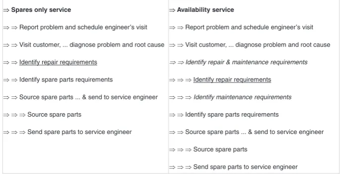
Examples of service breakdown structures, shown as indented [service element] parts lists, for the two kinds of contract intro-duced through the case study are given inFig. 5. It can be seen that each service (spares only and availability) has its own structure composed of process steps that are largely common across the two. Italics are used inFig. 5to highlight differences between the two breakdown structures. As with product breakdown structures,
a key benefit from these structures is that they highlight service elements needed to realise each service. For example, the spares-only service includes a process step called ‘‘Identify repair requirements’’; this also exists in the availability service but at a lower level of decomposition as part of the ‘‘Identify repair & main-tenance requirements’’ process step.
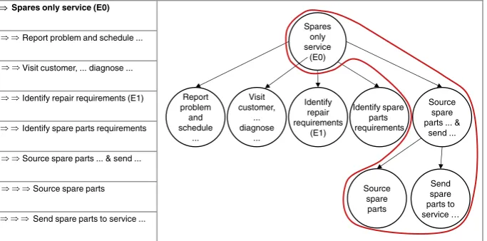
A schematic of the spares only service breakdown structure is given inFig. 6and a population of the information model for a part of this structure is shown inFig. 7.
A key difference betweenFigs. 4 and 7lies in the kind ofitem relationshipentity that is used:connectionrelationships inFig. 4 andcompositionrelationships inFig. 7. The process steps are again labelled with black stars; the numbers in the stars indicate the level of decomposition inFigs. 5 and 6 with zero indicating the top level of structure. However, since both process steps and rela-tionships between them are treated as first class objects the same service elements (in this case process steps and relationships between them) can occur in multiple service process flow and breakdown structures.
4.4. Definition of substitutions within service process definitions
As with product definitions, the definition of a service is unlikely to remain constant through its lifecycle and, for this rea-son, there is a need to be able to capture substitutions made as a result of change processes. The definition of substitutions within service process definitions is supported through a substitution entity based on the STEP substitution entity[26](seeFig. 8).
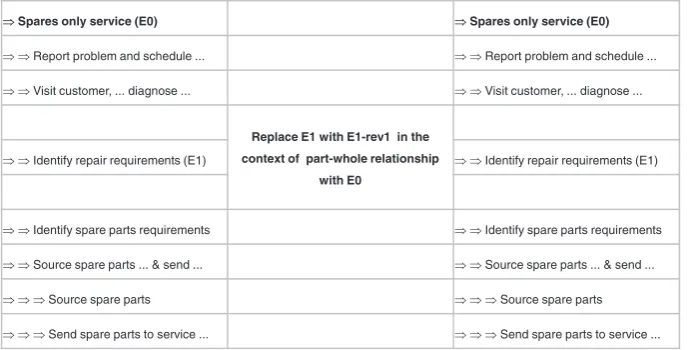
[image:8.595.121.465.563.739.2]A benefit of treating elements and relationships as first class objects is the additional expressive power that is achieved in com-parison with models, such as the STEP integrated resources, where relationships are dependent on the elements that they relate. For example, the information model inFig. 2capturessubstitution rela-tionships as a kind of connection relationship that relates a compo-sition relationship with a process step inFig. 10. An example of a service element substitution is given inFig. 9and the associated information model that supports its representation is given in Fig. 9. It can be seen that asubstitutionis defined as a subtype of aconnectionwhich, in turn, is a subtype of anitem_relationship; meaning that a substitution is a kind of connection that is used to connect parts of the service in a given time and/or context rather than flow-wise. An example instance is given inFig. 10where one process step is substituted for another. The example relates to process step substitutions because these occur in the case study. However, the information model is more general and could be used
to support substitution of any kind of item rather than just process steps; further work is needed to explore the implications and applicability of this generality. The context of the substitution is the part-whole [breakdown structure] relationship that connects the step being replaced to the rest of the service structure. An alter-native approach could be to substitute the relationships, which is possible because arcs and nodes are treated equally as first class objects in the underlying information model, in which case no text would be needed. However, in the longer term, if process con-nections are shared then this may not be feasible; more research is needed to understand the possible range of instances and their meanings and implications. An example instance of a service sub-stitution relationship from the case study is given inFig. 11.
4.5. Definition of service variants
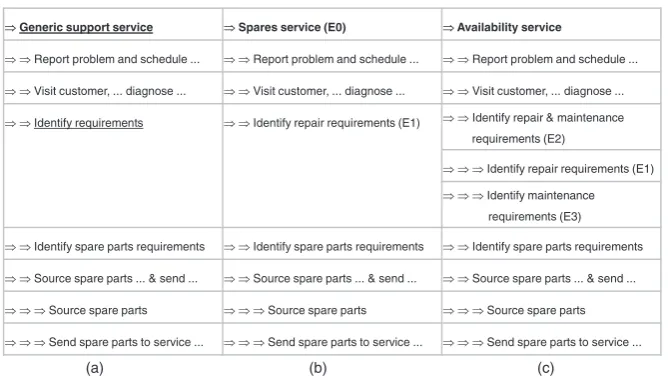
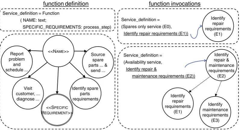
Substitution relationships are used to specify design changes across versions of a design. There is also a need to support the definition of variants of a design. The key difference between ver-sions and variants is that verver-sions reflect how a design (intended to meet a common set of requirements) changes over time whereas variants are responses to different sets of design requirements using a common solution architecture. Tidstam and Malmquist [66]report research on physical product variants and the design of product platforms as a common architecture on which designs delivering different functional requirements are built. In this paper we demonstrate how the definition of variants might allow variety and so customisation of service offerings. An example of service variants from the case study is given inFig. 12.
It can be seen that there are two service variants, one spares-only and the other availability, which both share a generic archi-tecture (see Fig. 12(a)) where the details of one step, ‘‘Identify requirements’’, depends on the kind of contract being delivered. If the variant is a spares-only service (see Fig. 12(b)) then the ‘‘Identify requirements’’ step is E1, ‘‘Identify repair requirements’’. On the other hand, if the variant is an availability service contract (see Fig. 12(c)) then the ‘‘Identify requirements’’ step is E2, Spares only service (E0)
Report problem and schedule ...
Visit customer, ... diagnose ...
Identify repair requirements (E1)
Identify spare parts requirements
Source spare parts ... & send ...
Source spare parts
Send spare parts to service ...
Spares only service
(E0)
Report problem
and schedule
...
Visit customer,
... diagnose
...
Identify repair requirements
(E1)
Identify spare parts requirements
Source spare parts ... &
send ...
Source spare parts
[image:9.595.134.476.68.237.2]Send spare parts to service …
Fig. 6.Example spares only service breakdown structure.
structured element
item relationship
composition structured
element relationship
structured element relationship
structured element relationship structured
element relationship
structured element
item
process step
structured element
item
process step
structured element
item
process step structured
element
item relationship
composition structured
element
item relationship
composition structured
element relationship
related relating
structured element relationship
structured element
item
process step
related
relating relating related
related
[image:9.595.101.497.273.481.2]relating relating related relating related
Fig. 7.EXPRESS-I-G of the right-hand branch (outlined in red) of the service breakdown structure in Fig. 6.
‘‘Identify repair & maintenance requirements’’, which includes both step E1 and a second step, E3, ‘‘Identify maintenance require-ments’’. The structure of these two service variants and the generic service architecture are defined using a functional notation in Fig. 13. Implementation of this notation would require a functional capability with the characteristic of lambda calculus where the [data] types of both functions and their parameters can be of any kind. For example, inFig. 13, theservice_definition function is of type service_definition; the function has two parameters, one is text, a string of characters, and the other is aprocess_step. As can be seen in the function invocations on the right-hand side of Fig. 13, the value of this second parameter can be either a simple process step or a process step that is composed of other process steps.
In this section product structure relationships have been used to demonstrate the principle of service variants. For a full imple-mentation, more sophisticated modelling methods would be needed such as the ability to represent instances as types[43]or reflective computing[63]. For this reason, an EXPRESS-I-G instance
is not provided for the definition of service variants.
5. Computer implementation
The representation scheme to support the definition of PSS structures was validated through population (see Section4) and through application to support a prototypical PSS definition system. In this section screenshots taken from this system are pre-sented and used to highlight key features of the representation scheme and the benefits it provides.
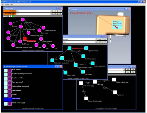
[image:10.595.123.467.68.243.2] [image:10.595.110.478.285.504.2]The screenshot given in Fig. 14 shows a product model that includes two design definitions: a bill of materials product struc-ture (containing part-whole relationships) in the top left-hand cor-ner of the figure and a Solidworks eDrawing in the top right-hand corner of the figure. These two definitions (the product structure defined using the representation scheme from Section4) and the CAD model are related to each other by relationships between the bill of materials and the eDrawing. These relationships can be seen by the highlighted (red3) parts at the bottom of the figure which change as the bill of materials is navigated. This functional-ity is the same as a Solidworks assembly tree, of which there are equivalents in other 3D modelling systems; however, including Fig. 9.An example of service substitution relationship.
the bill of materials in the PSS definition allows other relationships to be created as well. For example, the network shown in the bottom right-hand corner ofFig. 14shows a maintenance process definition of the kind that would be found in a service blueprint swim-lane. The red3highlighted area in this part of the screenshot highlights a relationship between the parts in the bill of materials and the Solidworks eDrawing and steps in the maintenance process (item to item relationships). A small number of these relationships are shown in the bottom left-hand corner ofFig. 14.
The screenshot shown inFig. 15includes all of the definition elements given in Fig. 14 plus a linkage to a supply network shown in the centre ofFig. 15. The definition of supply networks, which are defined as structured entities in a similar way to prod-uct and process elements of PSS, is outside the scope of this paper but is used to illustrate the value of representing relationships as first class objects. In this case the part in the product definition
(the ‘‘OK indicator light’’) highlighted in the top half of Fig. 15 is related to a flow in a supply network map. This allows users of the PSS definition to find out who supplied the part, for example, to support the acquisition of a replacement part, and demonstrates how the representation scheme presented in this paper can be used to define relationships between items in one structure (in this case, parts in a product structure) and item relationships in a second structure (in this case, a flow in a supply network). This is possible because, like the STEP integrated resources, relationships are represented explicitly in the underly-ing conceptual model.
The third kind of relationship across structures supported by the representation scheme presented in this paper is between pairs of item relationships. An example of this kind of relationship is given inFig. 16where a process step in the process model (Check fuse. Not OK’’) is related to a flow in the supply chain definition (‘‘fuse supplier – power connector’’ relationship). This flow, in turn, is related to an element in the product definition (a fuse). The definition of these kinds of relationship is possible because
structured element relationship
structured element
connection structured
element relationship
structured element
item
process step structured
element
item relationship
composition structured
element relationship
related relating
structured element
item
process step
related relating
item relationship
substitution related relating structured
element relationship
related relating
structured element
item
[image:11.595.105.498.68.293.2]process step
Fig. 11.EXPRESS-I-G of substitution example given inFig. 9in terms of the information model given inFig. 10.
Fig. 12.An example of service variants.
3
[image:11.595.136.471.328.520.2]relationships and elements are treated as equal, first class, objects in the underlying conceptual model. This contrasts with the STEP integrated resources where relationships can only be related to each other through elements of product structures.
6. Discussion
Nøhr Hinz et al.[52]provide a general framework for PSS devel-opment and use it to position a range of PSS develdevel-opment methods
Identify repair requirements
(E1)
Identify repair & maintenance requirements
(E2)
Identify maintenance requirements
(E3) Identify
repair requirements
(E1) <<NAME>>
<<SPECIFIC REQUIREMENT>> Report
problem and schedule ...
Visit customer, ...
diagnose ...
Identify spare parts requirements
Source spare parts ... &
send ... Service_definition = Function
( NAME: text;
SPECIFIC_REQUIREMENTS: process_step)
Service_definition =
(Spares only service (E0),
Identify repair requirements (E1))
Service_definition =
(Availability service,
Identify repair &
maintenance requirements (E2))
[image:12.595.93.492.67.285.2]function definition
function invocations
Fig. 13.Spares-only and Availability service definitions defined using functions.
[image:12.595.59.525.325.684.2]and tools. Bochnig et al.[10]provide a similar generic PSS develop-ment process as does Laurischkat[36]who then describes a gen-eral architecture for PSS-CAD systems. A common theme in these and other PSS development processes lies in the decomposition of the development process into series of process steps and stage gates which require key information elements. Information requirements elicited from representative PSS development pro-cesses, methods and tools are discussed in Section6.1with a view to informing the design of underlying PSS information support sys-tems. Like product-CAD (P-CAD), industry strength PSS informa-tion support systems are likely to include PSS-CAD systems from multiple vendors used across organisational and project bound-aries. The role of the representation scheme introduced in this paper is to support these information flows, especially at the later stages of the PSS development process, what Bochnig et al. refer to as ‘‘IPS2architecture specifications and definitions of product ser-vice modules’’, or the concept development and detailing stages of Nøhr Hinz et al.’s framework for PSS development. The efficacy of the representation scheme introduced in this paper is compared with similar schemes available in literature in Section6.2.
6.1. Information requirements of PSS development processes, methods and tools
Approaches developed in product definition communities can be used as a basis for the definition of information requirements for PSS development processes. Bochnig et al. [10] specify a
collection of thirteen requirements for a ‘‘general IPS2data model’’. The focus of the data model introduced in[10]covers two later stages of their general PSS development process and includes configuration, embodiment and detailed definition of PSS-CAD solutions. A detailed comparison of Bochnig et al.’s data model and the representation scheme introduced in this paper against selected requirements is given inTable 3.
Bochnig et al.’s other requirements are not included inTable 3 because detailed comparison between the models is not feasible given the available information. For this reason, these require-ments are discussed here.
6.1.1. Represent all the different elements of IPS24
[image:13.595.65.540.67.432.2]As with a number of Bochnig et al.’s requirements, further detail and precision in their formulation is needed to enable a detailed evaluation of different solutions. For example, like the first require-ment inTable 3(‘Support the entire planning and development pro-cess across all propro-cess phases’), systematic assessment against this requirement needs a clearer definition of what constitutes ‘all the different elements’. If the key elements are taken to be prod-uct–service modules where a given module is either a product or a service element then the representation scheme in this paper could be used to support the definition of service modules in a Fig. 15.support for maintenance activities – node to arc relationships.
4 ‘IPS2
manner that is compatible with existing product definition schemes.
6.1.2. Allow for combining IPS2elements to modules and thus modularisation of IPS2
More detail is needed of the kinds of modules and the nature of relationships between them for a detailed assessment against this requirement. Bochnig et al.’s model includes a ‘Product–Service module’entity that is a composition of a ‘Product Element’and a ‘Service Element’but the description of what constitutes a Prod-uct–Service module, how modules are selected and how modules are related needs further elaboration. Learning from the product definition community indicates that substantially more detail is needed before reliable data models can be created[67]. In this paper, the idea of a module is not explicitly covered but compara-ble functionality to Bochnig et al. could be achieved through the addition of aPSS modulesubtype to theitementity although more detail would be needed to determine appropriate attributes.
6.1.3. Be generic, not domain specific AND Preferably be simple, not too complex AND Be flexible and extensible
These requirements relate to general issues to consider in the development of any information model. Trade-offs, and associated benefits and drawbacks, between being generic and specific are widely reported and clearly visible in the STEP family of standards and associated literature. Without a clear application domain, which neither this paper nor Bochnig et al. provide, it is not
possible to comment on whether an appropriate trade-off has been made in either case. Requirements for simplicity, flexibility and extensibility are obviously desirable in the design of information models. Batini et al.[7]used three criteria in their comparison of database schemas (minimal, complete & correct, and understand-able). These were extended by McKay et al.[41]) for product data models to include conceptual (in an ANSI/SPARC three layer model sense), extensible (able to accommodate new information require-ments without corrupting existing instances) and structural integ-rity. Both this paper and Bochnig et al. introduce conceptual models with core entities that promise structural integrity and extensibility but neither is evaluated against these criteria. The population of the model presented in this paper coupled with the use of the model to support a computer implementation provide confidence that the model meets all three of Batini et al.’s require-ments. Similar assertions for Bochnig et al.’s model would be more difficult to support because a systematic population of the model is not provided.
6.1.4. Support different viewpoints
[image:14.595.59.526.67.422.2]the definition of instances but more detailed understanding of specific application views, and the PSS development activities each is intended to support, is needed to enable the development, verification and validation of proposed PSS representation schemes and ontologies. Substantial further work is needed in this area and could begin by building on research on PSS development processes, methods and tools cited elsewhere in this paper.
6.1.5. Allow traceability of results from preceding phases and process steps
Learning from product definition indicates that support for this requires management type data within the PSS data model and links between the PSS definition and PSS development process workflows. The data model presented in this paper does not address this requirement but anticipates future development of PSS lifecycle management systems as parallels to widely used Product Data and Lifecycle Management systems.
6.1.6. Allow links between partial models
Existence dependence is an important factor in creating solutions that address this requirement and is elaborated later in this section.
6.2. Data models for PSS definition
A number of authors distinguish between processes and activities. For example, (Nøhr[52] relate generic process to PSS development activities supported by individual PSS-CAD systems
that they review and Shimomura et al.[60]use PSS development activities to structure a discussion of emerging PSS design and development tools such as service engineering methods and their integration with engineering simulation tools. In the future, both PSS development processes and the PSS process definitions that result from them could be used to inform the development of work systems; Alter[3]distinguishes between processes and activities in a meta-model for the definition of work systems. These work systems will be underpinned by information systems and the rep-resentation schemes embedded within them.
[image:15.595.43.558.84.426.2]The majority of representation schemes for PSS definition available in the literature are in the form of data models. As with any model, validation and verification are important aspects of their development. McKay et al.[41]) identify two ways in which data models might be validated: through instantiation and application. The data model introduced in this paper has been validated using both methods (see Sections4 and 5respectively). In contrast to literature reviewed, the emphasis of this paper lies in the data model being reviewed rather than the PSS-CAD system to be supported. One limitation of all papers is the lack of benchmark PSS/IPS2 examples that can be used to compare the capabilities of different models and systems or the ontologies that underpin them. In this section we introduce a benchmark example based on a case study introduced by Umeda et al. [72] (seeFig. 17) to compare the functionality of the data model intro-duced in this paper (seeFig. 18) and a range of recently published PSS data models. The example was chosen for the following reasons:
Table 3
Bochnig’s information requirements for PSS definitions.
Requirement (direct quotes from[10])
Commentary [10]general IPS2
data model Data model presented in this paper
Support the entire planning and development process across all process phases
This requirement is aspirational but not testable, primarily because delivering this demands a clear definition of what constitutes ‘‘the entire planning and development process across all process phases’’ which is not yet evident from the literature
Supports the definition of IPS2 architectures comprised of product– service modules where a given product– service module is either a product or a service element
Supports the definition of PSS architectures comprised of product and service elements
The model is presented across stages of an IPS2
process but ways in which instances will be related to specific stages of specific development processes are unclear
Relationships between PSS definitions and PSS development process elements can be defined as instances of theprocess_step entity
Allow for development of concrete IPS2
instances for particular customers
Model does not explicitly support the identification of specific customers but this might be possible using features of the file system within which an implementation would sit
Model includes support for the identification of customers and their association with process steps that may be parts of PSS offerings
Allow the management of data for IPS2authoring
Again, management requires a process and tools; for a data model the requirement would be that data needed to support these processes and tools can be captured
Neither model includes management data. However, using STEP-like interpretation methods it would be possible to associate STEP management resources to elements of the data models and, through these resources, include management data in instances
Allow the modelling of the interdependencies between the IPS2elements (essential due to the focus on an integrated development)
Both models support the definition of relationships between PSS elements but a systematic assessment against this requirement would need more detail on the kinds of interdependencies to be represented
Data model supports the definition of instances that are collections of product service modules. Relationships between modules are implicit. Details of the cardinalities of relationships between modules are provided but not the kinds of relationship that can be defined
Data model supports the definition of relationships between service and process elements. Two kinds of relationship are explicit in the model: composition and connection. Cardinalities of these are not limited because this depends on the number of relationship entity instances that are defined. The paper demonstrates how these core relationship types can be used to support the definition of substitution relationships and considers their use to support the definition of PSS variants
Carry along results across phase borders
This demands the definition of data exchange interface requirements
The entities provided cover all phases of the process presented but the efficacy of the model against this requirement is not addressed
– it was created independently of the research reported in this paper;
– it is relatively small but includes the complexities that typically occur in PSS;
– it includes both product and service elements;
– it is the kind of definition that might result from a PSS development process.
Key features of the example are that it includes a product structure, a service structure and relationships between the two in the form of links between elements in the product structure and relationships in the process structure. In addition, as is often the case in process definitions, the process begins with a flow into an initial process step (in this case, an end-of-use phone into the Disassembly process step).Table 4provides a comparison of the data model introduced in this paper with a selection of recently published models.
The following meta-models were selected for this comparison: Alter[3](focussed on the part of the model related to product/ser-vice), Averbeck et al.[6], Bochnig et al. [10], and Uhlmann and Bochnig [70]. Each of these models satisfies two criteria: (i) it relates to later stages of a PSS development process where the goal is to create a PSS definition and (ii) the data model is presented in sufficient detail for a comparison to be carried out. The first crite-rion led to the exclusion of a number of models that relate to early PSS development, such as[50]. The second criterion led to the exclusion of a number of works that are very relevant to this paper such as that by Orawski et al.[54], where the paper includes exam-ple instances but with insufficient detail of underlying meta-mod-els used to define them. Similarly, Komoto and Tomiyama [32] describe the integration of data from Service CAD with a lifecycle simulator which, in a full implementation, would require a digital PSS definition, but the paper focusses on the PSS CAD system rather than the underlying meta models that might support such
Assembly Washing Disassembly
Inspection
Warehouse Disassembly
Shredding
Sorting
New parts
Remanufactured phone
Recyclable materials End-of-use
phone
Electrical module
Button
[image:16.595.144.443.68.281.2]unit Body part
Fig. 17.Benchmark example derived from literature (adapted from Umeda et al.[72]).
A
B
C
process step
S [0:?] subsequent_step
z x
y
process step
SET structured
element structured
element relationship structured
element relationship
structured element
process flow structured
element structured
element relationship
before after
structured element
process flow
structured element
structured element relationship
process step
process flow (1)
subsequent_ step
process step
process step A
C B
before after
process step
process step
A B
x y
before
after before after
[image:16.595.128.459.329.537.2]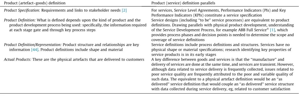
![Fig. 3. An adaptation of the general purpose information model from [42] to support process flows and part breakdown structures.](https://thumb-us.123doks.com/thumbv2/123dok_us/7948552.196788/7.595.111.496.321.564/adaptation-general-purpose-information-support-process-breakdown-structures.webp)