OPTICAL FIBRE COUPLERS
Andrew John Stevenson
A thesis submitted for the degree of
Doctor of Philosophy
Australian National University
Canberra
For you, Cathy,
Declaration
This thesis is an account of research undertaken in the Optical Sciences Centre, formerly Department of Applied Mathematics, in the Research School of Physical Sciences at the Australian National University between March 1984 and May 1987 while I was enrolled for the degree of Doctor of Philosophy.
This research was supervised by Professor Allan W. Snyder and Dr John D. Love, but unless otherwise indicated, the work presented herein is my own.
None of the work presented here has ever been submitted for any other degree at this or at any other institution of learning.
iii
PUBLICATIONS
A. J. Stevenson and J. D. Love, "Vector modes of six-port couplers", Electron. Letters, Vol. 23, No. 19, pp. 1011-1013, 1987.
A. W. Snyder and A. J. Stevenson, "Polarization splitters and birefringent couplers", Electron. Letters, Vol. 21, pp. 75-77, 1985.
A. W. Snyder and A. J. Stevenson, "Polished type couplers acting as polarizing beamsplitters", Opt. Letters, Vol. 11, No. 4, pp. 254-256, 1986.
A. W. Snyder and A. J. Stevenson, "Anisotropic couplers with non-aligned optical axes", Journal of Lightwave Technology, LT-6, No. 3, pp. 450-462, 1988.
CONFERENCE PRESENTATIONS
A. W. Snyder and A. J. Stevenson, "Birefringent Couplers", R.R.B. Workshop on Infrared Techniques for Coherent Systems, Melbourne, October 1984.
A. W. Snyder and A. J. Stevenson, "Birefringent couplers", Proc. I.R.E.E. 9th Aust. Conf. on Optical Fibre Technology, Wollongong, Australia, Dec. 1984.
A. W. Snyder and A. J. Stevenson, "Couplers composed of birefringent material", Digest of 3rd Int. Conf. on Optical Fibre Sensors, Optical Society of America, Washington DC, Paper THCC2, 1985.
A. J. Stevenson and J. D. Love, "Understanding six-port couplers", Proc I.R.E.E. 11th Aust. Conf. on Optical Fibre Technology, Geelong, Australia, Dec. 1986.
PUBLICATIONS IN PREPARATION
Weil, I must say, I've had a whale of a time.
But, seriously, there really have been some enjoyable moments in the course of this long and drawn out battle against leisure and free time, and I think we finally won - I’ve hardly had a free moment in 18 months...
I suppose I’d better do the time honoured thing and thank everyone. Thanks guys. And girls.
Now I guess I’d better name a few of you and say the good things...
Thanks very much Diana for doing all the nasty messy yucky equation typing in the last week and a half, including weekends and for sacrificing your Easter Ducky to make a few miserable students happy for a few minutes. You've been very patient and forgiving, particularly with Chapter 4 when I left off all the squiggly bits in the draft and you had to go through and put them all in later. And thanks to Mark for those snazzy tables in Chapter 6, and Stephen and John and all of the others in the Applied Maths Department who lent their assistance in trying to get the Macintosh to do little hats over the Greek letters in the text. Never mind, they'll just have to go in by hand.
Now, the academics ... what can one say...? First off the top of my head (after about 2/3 of my own hair), my two learned and accomplished supervisors spring to mind - Allan Snyder and John Love, who, despite endless pressing calls upon their time after writing the Black Bible, managed to slot me in for more than the occasional supervisory chat. I greatly appreciated your mathematical expertise, John, particularly in showing me why all that beating was so necessary for me to understand couplers, and I must say, Allan, that at times, you really gave me the concepts. You were both slowly varying, and I feel I now know what weak guidance really is.
senses. Thank you also, Adrian, for sharing your home and fresh vegies with me in 1986. They were delicious, but you must pick the zucchinis sooner, before they grow to the size of watermelons.
To my other living/housesharing companions in the last few years, particularly Grant Wilson, Peter Thygesen and Paul Sarvaas, thank you for your friendship and academic encouragement (e.g. "when are you going to finish that paper, Andrew?"). To Sister Madeleine of Ursula College, thank you for making me feel at home when I first arrived in Canberra, and for your warm welcomes to Ursula whenever I return to visit. My two years there were memorable ones.
To my fellow students over the ages, including Iain, Richard, Steve, Frank, Wanda, Zheng, Michael (passed over to Theoretical Physics in 1985) and others from those Protestant Colloid and Surface Forces groups, (a Schism in my own study-time), a big hello, and thanks for the company, cricket and commiserations.
I would also like to thank the possums for not pissing on my head too often at night as I walked under the birch trees out the front and the small wrens and finches in the bushes outside the office for keeping me company, even at 1.30 a.m., and for coming in and eating the dead insects on the floor in the office at times (particularly after the Bogong moth plague).
To the management and staff at AOFR, (all 40 of you and growing fast), thank you for your comeradeship and understanding in these last two tiring years, and for the opportunity of experiencing the experimental atmosphere I had always hoped to encounter from my earliest student days. At last I get to play with real optical fibre and to experience first hand the fruits of my theoretical labours on the very same devices I have written about here. I am indeed fortunate in this regard.
I would like to thank you, my family - Mum and Dad, for your love and support throughout my life, and to my new parents, Fred and Gay, for welcoming me into your life. Thank you all for the timely (frequent) reminders of the need to finish ... see, I did i t !
Coherent communications systems and other future optical fibre applications will require passive optical fibre couplers more sophisticated than the standard four-port couplers currently in use. This thesis is a theoretical study of six-port couplers, birefringent couplers and fibre optic polarizing beamsplitters, using the well-known normal mode approach to deduce their optical characteristics.
Chapter 2 provides the mathematical background, describing the derivations of the isotropic and anisotropic vector and scalar wave equations, and the validity of the scalar analysis for weakly-guiding, weakly-anisotropic structures. Scalar perturbation theory is also introduced as it applies to the analysis of evanescent couplers and birefringent fibres.
Chapters 3 and 4 describe in detail the lowest-order scalar and vector normal modes respectively, of the six-port evanescent coupler, of arbitrary isoceles cross-section. These modes are analagous to the fundamental and first-order modes of the circular fibre, to which they evolve when the three fibres are coalesced into a single circular structure. Symmetry principles are invoked to deduce the modes in certain limiting cases, including the equilateral array of three identical fibres.
Expressions for the scalar modal fields and propagation constants are derived in a general form in Chapter 3 using scalar perturbation theory, and these are used to determine the output power splitting and phase characteristics of sixport couplers. In Chapter 4, first order corrections from the vector wave equation are used to determine approximate forms for the vector modes, and the form birefringence of the three-guide array. The transition between the vector and scalar results is examined.
polarization vectors are generally not parallel to the optical axes except in certain limits. Form birefringence is dominated by material birefringence, and these couplers are characterised by the optical axis misalignment angle and the ratio of the two physical beat lengths in the system - the evanescent coupling length and the birefringent beat length. When the two beat lengths are equal, the opportunity for polarization cross-talk is greatest, with maximum cross-talk occuring for 45 axis misalignment. Polarization preservation is best in highly birefringent couplers with aligned optical axes. Power transfer and output polarization states are examined.
A U T H O R 'S P R E F A C E
The basic philosophy adopted in this thesis is to point out the physics o f each situ atio n w ithout squelching too deeply into the m athem atics. To this end, "real" calculations, (especially those involving majestic clusters of Bessel and Hankel functions of irrational order, nestled up to 6 deep inside m enacing triple integrals over the complex plane,) are avoided, and mentioned in passing only where they illustrate a point. Physical and m athem atical descriptions of couplers and their modes are generalized as far as possible, even to the point o f abandoning the cherished evanescent w eak-coupling requirem ent in some cases. The resulting physical description of propagation in couplers applies to many more regimes than those strictly allowed by a scalar perturbation analysis. For those odd occasions when I felt it necessary to lapse into numerical English, viz, the occasional equation, I condescended to m ake it easier for my innum erate brethren (or should that be innum erable ? ... no ... there w on't be more than 6 people reading this anyw ay) to keep track of the tw isted logic associated therew ith, by num bering each equation uniquely - hence (2 -l i b ) is the second sub-equation o f the 11th equation of chapter 2, and will always be referred to as (2 -l i b ) thereafter, unless I've goofed during one o f my m any re-num bering fits. Figures are num bered uniquely in the standard m anner, e.g. Fig. 4.3. Likew ise my chapter.section.subsection notation is o f the conventional type, e.g. 5.2.1 and so on. There is no appendix. (Yes, it was rem oved years ago.) Papers are referred to by author and year and are lumped together at the back of the thesis for ease of location, and to make the list look more impressive.
IX
CONTENTS
Declaration ii
Publications iii
Acknowledgements iv
Abstract vi
Author^ Preface viii
CHAPTER 1 : INTRODUCTION 1.0 Motivation
1.1 This Thesis
CHAPTER 2 : M ATHEM ATICAL BACKGROUND
2.0 Introduction 5
2.1 Optical Waveguides 5
2.2 Modes of Optical Waveguides 10
2.3 Wave Equations and Weak-Guidance 15
2.4 The Perturbation Approach 37
CHAPTER 3 : SCALAR MODES OF SIX-PORT COUPLERS
3.0 Introduction and Background 54
3.1 Physical Description of Evanescent 55 Six-port Fibre Couplers
3.2 Mathematical Analysis of the Three 81 Waveguide System
3.3 Conclusions 100
CHAPTER 4 : VECTOR MODES OF SIX-PORT COUPLERS
4.0 Introduction 103
4.1 Physical Description of Vector Modes 104 4.2 Mathematical Derivation of the Vector 118
Modes of the Six-Port Coupler
4.3 Transition from the Ideal to the 137 Non-ideal Six-Port Coupler
4.4 Conclusions 148
CHAPTER 5 : BIREFRINGENT COUPLERS
5.0 Introduction 149
5.1 Background 149
5.2 Physical Description 153
5.3 Modal Analysis by the Perturbation Method 161 5.4 Propagating Fields and Power Transfer 178
5.5 Conclusions 187
CHAPTER 6 : POLARIZATION SELECTIVE COUPLERS
6.0 Introduction 189
6.1 Background 196
6.2 Realization of the Fibre Optic 1 9 9
Polarization Beamsplitter
6.3 Analysis of Type I Polarization Splitters 207 6.4 Analysis of Type II Polarization Splitters 226 6.5 Practical Comparisons between the Two 240
Types of Polarization Splitter
6.6 Conclusions 245
1
CHAPTER 1
INTRODUCTION
1.0 Motivation
Optical communications systems, interferometric devices, sensor networks and other applications of optical fibre technology have created a need for specialized passive components, such as optical fibre couplers, at all points in the system - launch, branching networks, transmission sections and receiver ends. Future developments, such as coherent communication systems, will involve more sophisticated couplers than the standard four-port couplers widely used today.
In particular, multi-fibre devices such as the six-port coupler will find application in novel receiver configurations [Davis et Al, 1986, Stephens and Nicholson, 1987] and birefringent couplers will be required in polarization maintaining networks to prevent polarization degradation of the signals [Noda, 1986, Kawachi et Al, 1982]. The polarization splitter is a logical extension of the birefringent coupler [Nayar and Smith, 1983, Snyder and Stevenson, 1985] and has already found widespread use in bulk optic form; an on-line fibre polarization splitter has obvious advantages.
1.1 This Thesis
In Chapter 2, we review the justification for and description of the scalar perturbation technique for both isotropic and anisotropic waveguides. In doing so, we investigate the validity of the scalar wave equation which is an approximation to the vector wave equation derived directly from Maxwell's Equations, and identify the effects of form birefringence and material birefringence in weakly-guiding structures. This chapter lays the mathematical foundations for all of the results contained in the rest of this thesis.
In Chapter 3, the evanescent six-port coupler is modelled as a waveguide consisting of three fibre cores arranged in a triangular array, within an infinite cladding, a valid approximation when the cores are the principal guiding structure. When form birefringence of the three-core system is neglected, the three lowest-order scalar normal modes depend only on the separations and unperturbed propagation constants of the constituent fibres, at a given wavelength. These modes converge to the matching set of lowest-order scalar modes of the circular waveguide when the cores are coalesced.
Power transfer and relative phase between the fields in the output fibres of the coupler are determined from the scalar modes and propagation constants, calculated from scalar perturbation theory when the cores are weakly-coupled. Asymmetric input fields excite all three coupler modes and three length scales can appear in the power beating along the coupler. Couplers departing only slightly from the "ideal" equilateral shape are treated using a first order analysis, to show how slight separation errors or tiny discrepancies in the fibre uniformity can severely affect the output power splits and phases.
modes of the circular fibre, to which they evolve when the cores are coalesced. If the cross-section deviates even slightly from equilateral, the near degeneracy is split by the scalar differences between the modes, so the vector modes experience a transition to the LP scalar modes derived in Chapter 3. Over typical coupler lengths, the vector corrections to the output fields, relative phases and power splits are negligible. This completes the normal mode description of six-port optical fibre couplers.
In chapter 5, we investigate couplers composed of anisotropic fibres, which offer the possibility of maintaining input polarization throughout coherent networks and the like. Polarization cross-talk in birefringent couplers is analogous to polarization degradation in bireffingent optical fibres. This results from off-axis perturbations, with physical length scales shorter than or comparable to the birefringent beat length. In two-core birefringent couplers, each fibre acts to perturb the other on a length scale equal to the evanescent beat length. Polarization cross-coupling is therefore strongest when this length is comparable to the birefringent beat length of the two fibres and the optical axes of the two cores are misaligned.
The four lowest-order modes of the coupler with non-aligned optical axes are deduced from scalar perturbation theory alone, and exhibit novel polarization characteristics. When the optical axes of the two cores are parallel or perpendicular, the polarizations physically de-couple, and the coupler may be treated as two independent isotropic couplers, with LP modes. In all other cases with finite coupling and birefringent beat lengths, the modes are not LP, and the field vectors in each core lie between the optical axes. Power coupling exhibits two simultaneous length scales and the output fields are generally elliptically polarized for an LP input parallel to an optical axis.
step. Arranging for the two cycles to fall completely out of phase with each other provides the possibility of all of the power from one polarization emerging from one output fibre, while the orthogonal polarization emerges from the other fibre only. This is the realization of a Type I fibre polarization splitter, and can be used to polarize, split or combine two orthogonally polarized signals.
Another realization, called a Type II splitter, is obtained by arranging a birefringent coupler so that the fibres have matched propagation constants for one polarization, enabling total power transfer on a given length scale, while a mismatch exists for the other polarization, giving less power cross-talk (or none at all) on a shorter length scale. By tuning the length scales appropriately, it is possible to obtain polarization splitting as described above. Altenatively, if the fibres are sufficiently mismatched for one polarization, no power transfer is possible for that polarization, while the other polarization can transfer completely to the cross-port.
5
CHAPTER 2
MATHEMATICAL BACKGROUND
2 .0 INTRODUCTION
The purpose of this chapter is to provide the mathematical and physical groundwork for all of the results and concepts arising in this thesis.
After introducing the objects of our attention, namely isotropic and anisotropic optical waveguides and their natural modes of electromagnetic propagation, we show how Maxwell's equations lead to the general vector wave equations satisfied by the modes of both types [Marcuse, 1972, Snyder & Young, 1978, Snyder & Love, 1983].
The concept of weak guidance [Snyder, 1969, Gloge, 1971, Marcuse, 1972, Marcuse, 1974] is then used to simplify the analysis by reducing these vector wave equations to scalar wave equations, whose solutions accurately approximate the transverse components of the modes of isotropic and weakly-anisotropic waveguides. In doing so, we effectively ignore all of the polarization effects related to the waveguide geometry so that the only remaining birefringence and polarization corrections to the transverse field components result from material anisotropy in the guiding regions. In particular, we consider the scalar modes of isotropic (and thus anisotropic) step-profile single-mode fibres as these are of practical interest and are among the few profiles for which simple analytic results are obtainable.
2 .1 OPTICAL WAVEGUIDES
2.1.0 Descriptions of propagation in optical waveguides
Propagation in optical waveguides may be described by classical electromagnetic theory. Light confinement in waveguides much wider than the wavelength of the propagating light may be described in terms of total internal reflection of some or all of the light rays at one or more refradtive index boundaries, or a graded index region, using a geometric optics approach. [Ankiewicz and Pask, 1977]. This description does not apply in waveguides whose width is comparable to the wavelength of the light itself, since diffraction effects then dominate [Snyder et Al., 1974].
The most intuitively satisfying description of light propagation in optical waveguides involves the natural states of electromagnetic oscillation in the waveguide, the so-called "normal modes" of the structure. These modes are analgous to the natural vibration states on a bound string or stretched membrane, or the quantum mechanical states of a particle in a potential well [Black & Ankiewicz, 1985]. The description of the normal modes and their propagation in optical waveguides is based on Maxwell's Equations, from which wave equations appropriate to the waveguide may be derived. The number and form of the normal modes are determined by the refractive index profile of the waveguide, the wavelength of the light, and the size of the structure relative to the wavelength [Pask et AL,
1975, Snyder & Young, 1978].
The normal mode description applies not only to the optical fibre, but also to more complex waveguides, including the optical fibre coupler, which is a composite structure composed of two or more fibres, and supports various normal modes. The re-arrangement of light among the fibres along the coupler, called cross-talk, is a consequence of the simultaneous propagation of one, two or more of these normal modes, which are the principal subjects of this thesis.
2.1.1 Isotropic and anisotropic materials
In a linear optical material, an applied electric field, E, induces a proportional material polarization, P, and the displacement vector, D, is defined :
7
where e is the dielectric constant (or tensor) of the material and e0 is the dielectric constant for free space, in which no polarization exists. Refractive index of a material may be defined as the ratio o f the squares o f the dielectric constants of the material and of free space.
In some materials, termed "isotropic", P is parallel to E for all applied fields, and the refractive index n is therefore a scalar function o f position. The six-port couplers exam ined in Chapters 3 and 4 fall into this category. Other materials, by virtue o f their m olecular structure, or due to applied stress, for exam ple, are termed "anisotropic", since the magnitude and direction o f P, and hence D, depends on the direction o f E. In this case, the dielectric constant e in (2-1) is a tensor, and so too is refractive index, n. The birefringent couplers and polarization splitters discussed in Chapters 5 and 6 possess material anisotropy.
The refractive index tensor is expressable as a 3 x 3 matrix generally, since E and D are vectors in 3 dim ensions. Equivalently, the tensor may be written in dyadic form [W eath erb u m , 1937]. The anisotropic w av eg u id es exam ined in this thesis are w eakly-guiding (see below) and E and D are thus co-planar in the transverse plane of the waveguide, so for convenience, the refractive index tensor is generally reduced to a 2 x 2 matrix.
For certain polarization directions, known as the "optical axes" o f the material, P is parallel to E, so if we choose to express the 2 x 2 refractive index tensor in reference to these axes, it may be written in diagonal form :
n2t (2-2a)
where the subscript t denotes "transverse" and a and b denote the optical axes o f the m aterial, and are not necessarily uniform throughout the m aterial but may be defined locally. In the equivalent dyadic notation :
For convenience, decomposition is generally effected with respect to the local optical axes, w hile spatial co-ordinates, used to describe the variation of each tensor elem ent with position, are chosen to suit the geometry of the refractive index structure, usually cartesian or cylindrical for the study of longitudonally invariant waveguides, as in this thesis.
If we decom pose with respect to other axes, the tensor is not diagonal, but rem ains unchanged physically. Specifically, if c and d are another set o f axes, rotated by angle 9 , the tensor m ay be rewritten with respect to c and d:
In isotropic m aterials, a special subset o f the anisotropic materials, the tensor is always diagonal, regardless o f decomposition axes, since n a = nb .
2.1.2 Refractive index profiles
The elem ents o f the refractive index tensor are themselves scalar functions of position in the transverse plane, in longitudinally invariant waveguides, as shown in Fig. 2.1(a). The refractive index of a general optical fibre consists of an axially symmetric raised region, with finite radius p, say, and m axim um refractive index nco , surrounded by a uniform cladding o f index nc8 , to optically isolate the core from the surrounding air or jacket, as shown in Fig. 2.1(b). We may define the "profile height parameter" as :
The larger A is, the m ore strongly guiding the fibre is, for a given radius, and for a given A , larger fibres provide stronger guidance.
Fig. 2.1(c) shows two exam ple refractive index profiles o f optical fibres in widespread use, namely the step-circular-profile and the finite-parabolic circular profile.
nj cos20 + n2sin20 (n2 - n2) cosösinÖ n2 =
(nj - n2) cos0sin0 n2 sin20 + cos20
(2-3)
9
(a) Optical fibre geometries :
(i) Cartesian co-ordinates (x,y,z)
(ii) Cylindrical Polar co-ordinates (r, (j) ,z)
(b) Refractive index profile for the generalized cylindrically symmetric fibres, with core radius p .
(c) Examples of fibres which can be treated analytically : (i) Step-circular profile fibre.
These are among the relatively few profiles which may be treated m athem atically by analytic means. In practice, single mode fibres have core radii between 5 and 10 microns, and 0.002 < A < 0.01, while the more strongly guiding multi-mode fibres have virtually unlim ited core size and 0.01 < A < 0.03. Some fibres possess no core, relying instead on the large air-glass index boundary to guide the light, so that A is around 0.3.
In this limit, known as the weak-guidance limit, the fields o f the fibre are only weakly confined, with much o f the light propagating in the cladding, as evanescent fields. Even in this limit, however, in normal optical fibres, the field at the outer cladding-air boundary is vanishingly small. Thus, we ignore the effects o f the outer boundary in our analysis and assume a boundless cladding of refractive index nc3. By contrast, in tapered waveguides, e.g. fibre couplers, the core may become too small in the taper waist to effectively guide the light, and m ost propagates in the cladding. This requires a more sophisticated w aveguide m odel, accounting for the outer cladding boundary. In this thesis, for simplicity, we invesigate only infinite cladding models.
2 .2 MODES OF OPTICAL WAVEGUIDES 2.2.0 Decomposition of the field into modes
In a uniform dielectric waveguide, both guided and radiated pow er may result from the propagating electric and magnetic fields. We may express E(x,y,z) and H(x,y,z) as finite sums o f the forw ard and backward propagating guided modes, and the lumped radiation field terms [Snyder & Love, 1983] :
W hen A is very small, we may approximate :
^ — ( Tc o ” / ^ C O (2-4b)
M M
E(x,y,z) = u.E.(x,y,z) + u.E.(x,y,z) + Erad(x,y,z) (2-5a)
H(x,y,z) = u.H.(x,y,z) + ^ u^H .(x,y,z) + Hrad(x,y,z) (2-5b)
j=i j=i
The waveguide supports the same number, M, of bound modes in each direction. The factors, ilh are (complex) modal amplitude constants, the same in both expansions, from
Maxwell's equations. We consider only the bound forward-directed fields in uniform lossless waveguides, since the backward-propagating and transient radiation fields arise due to longitudi nal variations, sources or perturbations in the fibres, which we will not be examining in detail.
Thus, in our waveguide models, an input field excites a combination of the bound, forward-propagating modes Ej(x,y,z) (j = 1,...,M) and, in the absence of mode-mode coupling due to longitudinal variations in the waveguide, the amplitude coefficients u.(j = 1,...,M) remain constant thereafter.
The jth mode of a longitudinally invariant waveguide may be expressed in separable form, from Maxwell's Equations :
iß.z iß.z
E.(x,y,z) = e.(x,y)e J ; H.(x,y,z) = h.(x,y) e J (2-6)
where we have implicitly assumed a time-varying phase factor, exp(-icot), in ej(x,y) and hj(x,y) to give the travelling wave phase factor exp[i(ßjZ - cot)] corresponding to forward propagation at a phase velocity of Vj = co/ßj .
Although the amplitude of each bound mode is unchanging along the waveguide, the resulting fields may show variation with distance, since the relative phases between the m odes change as they propagate, causing beating between the modes. This interference merely rearranges the propagating power without affecting the total time-averaged power traversing the infinite cross-sectional plane of a lossless waveguide. Total power is given b y :
to the longitudinal axis and * denotes complex conjugate.
In a uniform waveguide, the re-arrangem ent o f confined pow er is a beating phenom enon, as opposed to a coupling phenomenon, since the pow er propagating in each bound m ode rem ains constant. "Coupling", strictly defined, is the transfer o f power between the modes them selves, e.g. due to perturbations or variations in the waveguide structure.To see why modal power is conserved in the invariant case, note that Maxwell's Equations and their boundary conditions on a non- absorbing z-invariant waveguide lead to the vector mode orthogonality condition
J e. x h * . $ dA = J ek x h* . z dA = 0 if j * k (2-8)
Aoo Aoo
O rthogonality o f two m odes is a global condition, as we see in later chapters. The amplitudes and polarizations are so arranged that the integral in (2-8) evaluates to zero over the entire cross-section, even if the modes do not have perpendicular polarizations or opposite scalar symmetries about some axis.
(2-7)
where "Re" denotes "real part", A^is the infinite cross-section, z is the unit vector parallel
1 3
^TOTAli2 ) TOTAL' 2
S
^ *Uj^J
6j X ' Z ^ -fJ=l A ,
(2-9)
'The pow er in each mode is fixed and proportional to the square of the amplitude constant multiplying that mode in (2-5).
Thus, total pow er traversing the infinite cross-section is constant along the waveguide, and the pow er in each mode is also constant, but the power traversing a subset o f the infinite plane may not be. M odal interference may cause the fraction, q R (z), of pow er traversing a given region, R, in the w aveguide cross-section to vary along the waveguide, where
The region R may correspond to a fibre core, in a coupler, for example.
2.2.2 Length Scales due to Beating between Modes
W hen two modes having different propagation constants, ßj and , propagate sim ultaneously along a waveguide, they alternately fall into and out o f phase with each other, causing periodic longitudinal beating of polarization or pow er or both, in various regions in the cross-section o f the waveguide. A fter a length 27t/lßj - ß^l, the initial phase relationship between the modes is re-established.
A simple example is the four-port evanescent optical fibre coupler, consisting of two identical fibres in close proxim ity, shown schem atically in Fig. 2.2(a). Such fibres may be fabricated using a lapping/polishing method, in which the cores are exposed to each other by selective cladding removal, or by a fusion and tapering technique, in which the cores shrink and are brought together. Both types are illustrated in Fig. 2.2(b,c). Power launched into one fibre at z = 0 excites an even and an odd mode o f the coupler, which are characterized by different propagation constants ß+ and ß- respectively. The closer the cores, the greater the difference between these propagation constants. The fields of both normal modes are concentrated in the fibre cores.
(2-10)
FIG. 2.2
(a) Four-port optical fibre coupler - schematic. Light launched into port 1 emerges from ports 3 and 4 in some arbitrary ratio.
(b) Two realizations of four port couplers - polished (lapped) and fused taper. Dotted lines refer to the cross-sections in (c).
[image:25.565.103.489.57.609.2]As the modes propagate, and their relative phase changes, the field and hence power in each fibre varies sinusoidally. Thus we can consider the coupler to be characterized by a beat length, inversely proportional to ( ß+ - ß- ) , which depends on the coupler geometry at each position; the closer the fibre cores, or the more tapered the coupler, the shorter the evanescent beat length becomes. The power splitting ratio at the output depends on this difference between the propagation constants, integrated over the length of the coupling region. [Snyder and Young, 1978, Snyder and Love, 1983, Chapter
18].
The coupler can also be treated using the so-called "coupled-mode theory" [Snyder, 1972, McIntyre & Snyder, 1973] in which cross-talk is described as coupling between the modes of the individual fibres within the coupler. While this approach is formally exact, and gives accurate results for weakly guiding, well-separated fibres, it is not as physically intuitive as the normal mode interference approach, since the fibre "modes" are not real modes of the coupler. Also, it does not extend conceptually to tapered couplers and is difficult to apply to birefringent couplers.
Another beat length relevant to this thesis is associated with the two orthogonally polarized fundamental modes of a birefringent fibre. Light launched at an angle to the optical axes of such a fibre excites both of these modes and, because of their different propagation constants, there is beating between them, resulting in a periodic variation in the polarization state along the fibre, generally from linear to elliptical and back again. After each beat length, the polarization state returns to the input state. The more birefringent the fibre is, the shorter is its birefringent beat length.
2 .3 WAVE EQUATIONS AND WEAK-GUIDANCE 2.3.0 Motivation
vector wave equations for the waveguides, derived directly from Maxwell's Equations. The true "vector normal modes" of the couplers follow from these vector equations, and are determined not only by the evanescent coupling between the fibres, but also by the geometric or "form" birefringence due to the shape and gradient of the waveguide index boundaries, not accounted for by the scalar analysis. Strictly speaking, therefore, the scalar normal modes are not quite correct, but predictions about phase and power transfer based on the scalar approach are still accurate, provided polarization effects are small.
It is useful, therefore, to know for what situations this scalar perturbation analysis is applicable, and what polarization-based effects are ignored by neglecting form birefringence. The vector equations can also be used to provide polarization corrections to arbitrary accuracy to the scalar analysis, and thus allow us to deduce more realistic approximations to the vector normal modes without having to solve the vector wave equations directly.
2.3.1 Maxwell’s equations for isotropic waveguides
Maxwell's equations for the electric field E(x,y,z) and magnetic field H(x,y,z) of an isotropic optical waveguide free of real charges and currents may be expressed in the form :
V x E = - n 0H = ik(iye0)l/2H (2-1 la)
V x H = eE = ikn2(e0/|x0)1C E (2-1 lb)
V . (eE) = e0V . (n2E) = 0 (2-1lc)
V . (nH) = nQV . H = 0 (2-1 Id)
wavenumber, k = Ik/ X throughout this thesis, where X is the free-space wavelength of the light being used. Note k = co/c, where c = (s0| i 0)-1/2 = 3 x 10⁸ m/s is the free-space velocity of light.
The field solutions are subject to boundary conditions across any interface between dielectric media of different refractive index:
(i) The total magnetic field and the component of the electric field tangential to the interface are continuous, and
(ii) The normal component of the electric displacement vector is continuous across the interface.
These conditions give rise to form birefringence in waveguides.
2.3.2 Vector wave equations for the isotropic waveguide
On a non-absorbing z-invariant waveguide, n2 = n2 (x,y) and is pure real. In this case, the modes can be written in the separable form (from (2-6)):
E(x,y,z) = Et(x,y,z) + Ez(x,y,z) z = (et + ez2 ) elßz (2-12a)
H(x,y,z) = H t(x,y,z) + Hz(x,y,z) z = (ht + hz i ) elßz (2-12b)
where ß is pure real, and the subscripts t and z denote the transverse vector components and longitudinal scalar components respectively. Any suitable set of spatial co-ordinates may be used, independent o f the axes chosen for the vector decomposition o f E and H.
Taking the curl (VX) o f (2-1 la) and using (2-1 lb) to eliminate H gives
V2E + k V (x,y)E = V(V . E) = - V [e, . V t «n(n2)] (2-13a)
We have made use of the z-invariant refractive index profile, and the vector operators have their usual m eanings. In particular, V t = V - iß z and V t2 = V 2 - ß 2z2 . Similarly, eliminating E gives :
waveguide, and are exact for any profile.
From (2-13), similar equations can be derived for the cartesian components of E and H, and are given in Eq. 30-18 of [Snyder and Love, 1983]. In weakly-guiding structures, the z-components are small enough to be of little concern in this thesis, so we refer mainly to the transverse fields henceforth.
2.3.3 The isotropic scalar wave equation
The transverse cartesian components are coupled by terms on the right side of (2-13), which involve the geometry of the waveguide index boundaries, giving rise to polarization effects and form birefringence, even while the material itself is isotropic. In isotropic waveguides, these coupling terms uniquely determine the mode polarization directions. The only exceptions,on c e r ta in dielectric waveguides;are the so-called TE modes - modes with ez = 0 everywhere. In this special case, (2-13) separates into de-coupled equations, for each cartesian component of the electric and magnetic fields, of the form :
(V f+k2n2(x,y)-ß2) v = 0 (2-14)
where is a scalar function representing ex , ey , hx orhy in this case.
The scalar w ave equation has found w idespread use in the analysis o f simple
w aveguides, notably in finding scalar m odes and propagation constants in planar dielectric
w aveguides and optical fibres o f circular cross-section.
It can be show n that the solutions o f the scalar w ave equation and th eir first
derivatives are everyw here continuous and bounded. C ontinuity follow s from the fact that
the second derivative contains at m ost a step discontinuity (from the scalar w ave equation
itself), w hile boundedness follow s from continuity and physical constraints on the field and
index profile. (In particular, the total energy propagating in any m ode m ust be finite.)
T hese p ro p erties allow us to fin d the scalar p ro p ag atio n co n stan ts from an
eig en v alu e eq u atio n and hence the scalar field solutions them selves. The m odes o f the
step-circular-profile fibre are derived in this m an n er in [Snyder & Love, 1983], and their
circular fibre results, outlined briefly now , are used in this thesis, w here appropriate.
In the step-circular-profile fibre, the transverse m odal fields are found by solving
(2-14) w ithin the co re and cladding separately, and m atching the solutions and their first
derivatives at the circular boundary. The solutions, \\f (r, (b), m ust take the separable form
w here fi is an integer. D efining R = r/p be the norm alized radius, w here p is the fibre
radius, the fields turn out to be solutions o f B essel's Equation :
\|/(r,($)) = F { (r/p) cos(fi<|)) or F4(r/p)sin(c<j>) (2-15)
J , (UR)/J,(U) R < 1
(2-16)
K£WRyKs(W) R > 1
w here U and W are n o rm alized scalar m odal p ro p ag atio n p aram eters in the core and
20
These parameters are related to the normalized frequency parameter, V :
Ml
V = kp(n?0 - n* ) = (2 A)1/2 kpnco = (U2 + W2)1'2 (2-17c)
The propagation constant is found by solving for U(V) from an eigenvalue equation arising from the matched-derivative boundary condition. For a weakly- guiding fibre, ( A « 1), the plots of U against V for some of the lowest order modes are shown in Fig. 14-4 of [Snyder & Love, 1983]. Each mode is assigned two integers, (f,m) to denote the mth solution of an fth order Bessel equation, arising from the eigenvalue equation, (j? is the subscript in (2-15) and (2-16).) Thus, the fundamental mode is the E = 0 mode, the ß = 1 modes are the first order modes and so forth.
As V decreases, the fibre becomes less guiding, and the fields spread into the cladding. The propagation constants decrease and modes progressively become "cut-off’, since bound mode propagation constants must lie in the range
kncl < ß < küco (2-18)
For all modes except the fundamental, there is a V value below which the mode cannot propagate. Cut-off occurs when U = V. Fibres in which all higher-order modes are cut off are called single-mode or monomode fibres.
Of particular interest to us in this thesis are the fundamental (E,m =0,1) and first order ( £,m =1,1) scalar modes of the step-circular-profile. The modal intensity patterns, proportional to \|/2 at each point, are shown in Fig. 2.3, together with vector field directions in each region for LP scalar modes. Both spatial axes and polarization axes must be defined.
21
FIG. 2.3
Intensity patterns and x-y symmetric polarization vectors for the fundamental 0 - 0 ) and first-order (8 = 1) LP scalar modes of the step-circular-profile fibre, from (2-15) and
[image:32.565.49.506.58.653.2]not come from the same wave equation, since ß is present in (2-14). Within this constraint, however, we are free to add two orthogonally polarized versions of one mode, or two arbitrarily polarized scalar modes with different spatial distributions to obtain an infinite number of possible hybrid modes. Of these, only certain unique combinations will approximate the allowed solutions of the vector wave equation, since it does not share the linear additive property of the scalar equation, due to the coupling terms on the right side involving the field.
The polarization axes in Fig. 2.3 are chosen for symmetry reasons to fit in with the vector transitions to the modes of the elliptical fibre, to be discussed below. The LP scalar fundamental modes efx and efy are degenerate, as are the four LP scalar first-order modes, eex , eey , eox and eoy .
2.3.4 Polarization effects in isotropic waveguides
Coupling between the polarizations, due to index boundary effects, occurs when two or more modes found from the scalar wave equation (2-14) are degenerate or almost so, i.e., when the difference between the "scalar" propagation constants is smaller than or comparable to the form birefringence resulting from the terms on the RHS of (2-13). The resulting modes have hybrid polarizations, and in weakly-guiding fibres, are well-approximated by combinations of the degenerate LP scalar modes. The "vector" propagation constants are given by the scalar values, slightly split by the form birefringence.
A good example, shown in Fig. 2.4, is the set of first-order vector modes of the circular fibre, which are well-approximated in weakly-guiding fibres by special symmetric combinations [Snyder & Young, 1978] of the degenerate first-order LP scalar modes shown in Fig. 2.3. The fundamental vector modes remain degenerate, but the 2 = 1 degeneracy is split when we include polarization-related effects from (2-13). Even the fundamental mode degeneracy can be split by form birefringence if the fibre is slightly elliptical [Love et Al., 1979].
23
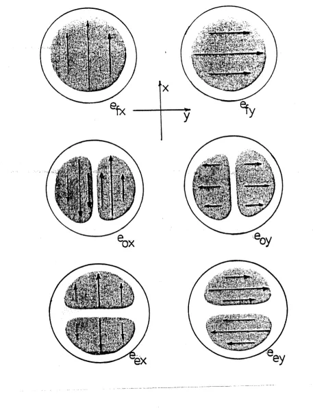
(a) Polarization directions for the first-order vector modes of the step- circular-profile fibre. The four modes are given approximately by circularly symmetric scalar mode combinations, eox - eey , 6ex - e0y , eox + eey , and 6ex + eQy .
(b) Optical intensity pattern for the four
2
= 1 vector modes in (a).FIG . 2.5
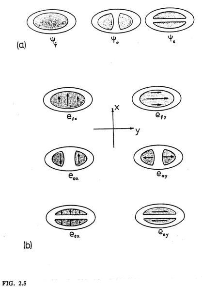
(a) Fundamental (£=0) and first-order (F=l) scalar modes patterns for an elliptical step-profile fibre. These modes are non-degenerate.
(b) Exact LP vector modes of the ellipse, polarized parallel to the geometric ellipse axes, and well approximated by the scalar fields when the waveguide is weakly-guiding ( A «
[image:35.565.59.476.58.652.2]25
coupling by terms on the RHS of (2-13) becomes negligible. In this case, the true vector modes are very accurately approximated by the LP scalar solutions of (2-14), as shown in in Fig. 2.5 for the elliptical fibre. The smooth vector transition between the degenerate hybrid modes and the non-degenerate LP modes is governed by the ratio of propagation constant splitting due to the scalar equation (2-14), and due to form birefringence from the vector wave equation (2-13). The modal transition from the circular fibre to the elliptical fibre is quantified in [Snyder & Young, 1978], (see Fig. 2.4(c),) and shows that very slight ellipticity can result in LP modes.
2.3.5 Weakly-guiding isotropic waveguides
The isotropic scalar wave equation, (2-14), and its solutions may be regarded as an approximation to "zeroth-order" in A of the exact vector wave equation and its solutions. All polarization effects in isotropic waveguides are then considered as higher-order effects, weak enough to be ignored when A « 1, so that the transverse field components are well-approximated by the LP scalar solutions. This constitutes one of the fundamental assumptions of the weak-guidance approach. [Sammut et Al, 1981, Love et AL, 1982]
A second approximation arises when we consider the bounds on the propagation constant given in (2-18). For small A , nco s nc8 and the bound mode propagation constants must therefore satisfy
ß e knc{ s knco (2-19)
This is the propagation constant for a forward-directed plane wave in a medium of uniform refractive index nco( e ncfl ). Thus, the modes of weakly-guiding structures must be
essentially polarized in the transverse plane of the waveguide, and the longitudinal electric and magnetic field components are approximately zero to lowest order in A .
We now discuss the accuracy of these two approximations.
respectively, while the scalar approximations to the transverse field and propagation constant found from the (2-14) may be denoted et and ß . We may expand et , ez and ß , as well as other relevant physical quantities, e.g. the modal parameter, U, and the (In (n2 )) term on the right side of (2-13), as series in powers of A, where the zeroth order term in each series is the scalar value assumed in the weak-guidance limit. For example,
et = et + et(1) A + et(2) A2+ ... (2-20a)
(1) (2) 2
ß = ß + ß A + ß A + ... (2-20b)
where superscripts in parentheses denote the order of the correction term, and each coefficient is independent of A if all other parameters (e.g. V ) are held fixed. The coefficients are found by expanding the wave equation completely in orders of A , solving and equating like powers. Using this approach, it turns out [Love et Al, 1982, Snyder and Young, 1978] that lowest order terms in the series for ez and hz are of order (A)1/2 , and so, in the weak- guidance limit, the z-components of the fields are zero, as expected. Other field component correction terms are contained in [Snyder & Love, Table 32-1].
Neglecting form birefringence and the resulting split in propagation constants may lead to large errors in the predicted phase in long waveguides, and incorrect predictions of power splitting in couplers. By contrast, errors due to neglecting corrections to the transverse scalar field approximations remain small and unchanging along the waveguide. Thus, if field corrections can be ignored at the start of a waveguide, then they may be ignored altogether.
27
The difference between the exact propagation constant ß and the scalar approximation ß is given by an integral expression over the infinte cross- section, obtained from (2-13) and (2-14), which holds exactly for all profiles:
ß2 - ß =
J
(Vt . et) et . Vt (m n2) dA /J
et . et dA (2-21)A . A .
To lowest order in A , using series expansions, it can be shown that
3/2
P - ß = ■ ^ r e- J (Vt . et) e , . Vt f dA / Je* dA (2-22)
A - A*,
where f is a function describing a generalized refractive index profile :
n2(x,y) = n20 [l - 2A f (x,y)] (2-23)
For step-index profiles, (in which f is a step-function in (2-23)), the area integral in the numerator converts to a boundary line integral:
3/2
ß - ß = (2A2y p
J(Vt.e,)
v t i d u /J
e *dA (2-24)« A
-A ,
where n is the unit outward normal vector at the index boundary, .
This correction depends on waveguide shape and is proportional to (A)3'/2 for fixed V and p. It is generally polarization-dependent as well, except where modes are symmetric about two orthogonal axes, so form birefringence is proportional to (A)3/2 when V is constant. V depends on p and A, so the form birefringence is proportional to A/knco in general. For TE modes, which are exact solutions of the scalar wave equation, there is no correction.
over the length of a waveguide. This only occurs if the waveguide is a significant fraction (say 1/8) of the form birefringence beat length, which is proportional toV(A}'3/'2 . Vv'h^r a « l therefore, we may ignore form birefringence in couplers, which tend to be short. Also, m aterial anisotropy, w hen present, is usually strong enough to overw helm form birefringence in weakly guiding structures, as we discuss below.
2.3.6 Maxwell's equations for the anisotropic waveguide
In an analogous fashion to the isotropic waveguide, Maxwell's equations for the fields in a source-free anisotropic m edium (characterised by tensors for the dielectric constant and refractive index) may be written:
V X E = - n 0H = ik(H</£0) 1/2 H (2-25a)
V x H = e E = -ikfEg/n,))1' 2 n2E (2-25b)
V . (eE) = e„ V . (n2E) = 0 (2-25c)
V ,(hH) = h0 V .H = 0 (2-25d)
where n2 = n2 (x,y) in a z-invariant waveguide. The electric and magnetic fields may once more be written in the separable form o f (2-12) and the index tensor is locally diagonal when the chosen cartesian com ponent axes correspond to the local m aterial optical axes. Other quantities in (2-25) are defined previously.
2.3.7 Vector wave equations in the anisotropic waveguide
Taking the curl (V X) o f (2-25a) and using (2-25b) to eliminate H gives
29
Similarly, eliminating E leads to
V X [n '2 . (V X H)] = k2H (2-26b)
w here n 2 = r r 2 (x,y) is a diagonal tensor with elem ents na*2 (x,y), nb*2 (x,y), and nz‘2 (x,y). These are the vector wave equations for the fields on an anisotropic waveguide, and are exact for all profiles. W e can find the wave equations satisfied by each cartesian com ponent of E and H by expanding (2-26):
( v ^ . i [ ( 4 ) | . (/ nr N 9e,1— ) —
^ 4 ab
2 _2
' * ‘ ^2 Sb
]
(2-27a)
(vf + k V - ß % =
ir
O A )
[
A +I1--?)
I T - ~Teä 4 /tnna)- “K ^ " “b)]
3b L 3a ^ 3b n2 a3a
(2-27b)
(vf+kVz
ß2X = iß [ ( l - | ) | e a|< « m 2)- - | e b|{ m n 2)](2-27c)
(vf+k2n2-ß2)ha=(i4)vfha+4- 0ß\ (44) $ 4(lf - $■)
2' 1 a v 2 n£ nj 9a n2 3b 3a 9b$
(2-27d)
(v; * knJ-ßX - 0 - §W >. * ( | ) » \ * ( | - |>H y * | < x - y ) 5- <“ *
(2-27f)
These expressions are exact for any profile, provided the fields are decomposed into cartesian components parallel to the local optical axes of the material. Note, the fields E and H themselves are not necessarily parallel to the local optical axes, particularly if the anisotropy varies in magnitude and direction throughout the entire cross-section. Analytic solution of (2-27) is therefore possible only in simple cases.
2.3.8 Weakly anisotropic, weakly-guiding waveguides
In this thesis, studies of anisotropic systems are restricted to four- port couplers in which the material anisotropy is confined to the two cores, with uniform optical axes throughout each core. Furthermore, we only consider weakly-guiding systems in which the anisotropy in the refractive index profile is much less than the profile height itself. Thus, if we define the "profile anisotropy parameters":
(2-28a)
(2-28b)
31
then the waveguide is "weakly-anisotropic" when 5^ « A (i,j = x,y,z) and the
approximate forms may then be used. Note that 5 ^ = 5 ^ - 8ab .
A convenient, and not unrealistic, assumption is that the refractive index
components, na2 , nb2 , nz2 are proportional to each other such that na2 / nz2 and nb2 /
nz2 are independent o f position in the anisotropic region. This always holds in step-profile
waveguides and holds approximately in w eakly-anisotropic, w eakly-guiding,
graded-profile systems w ith no sharp "bumps" in the refractive index profile for any
polarization. This allows us to remove the subscripts from the squared index terms inside
the logarithms on the right hand side, and write fin(n2) instead, since only derivatives of the
logarithms appear here. Putting this assumption into (2-27), and inserting (2-28), we
obtain the following vector wave equations for et and ez
(v?
+ k2n?-ß2)et =- vt{
[28.V,] . et + [25teJ . V ^n n 2)+ et . Vt($nn2) } (2-29a)
(vf +
k2n2 - ß2)e,=
-iß{ [25tv j .
et+
[28te,] . Vt(«nn2)+ et . V^ain2) } (2-29b)
where 25t = (nt2 - nz2 )/na2 is a 2 x 2 (a,b)-symmetric tensor :
25t = [aa(n 2 - n2) + fefi(n2 - n2)] / n2 = 2 (5azaa + 5bz66) (2-29c)
Corresponding equations exist for the components o f H. This wave equation is analogous
to the isotropic wave equation (2-13), to which it reduces when anisotropy is zero, since
the tensor o f (2-29c) vanishes. Only (2-29a) interests us from here on, since ez is
2.3.9 The anisotropic scalar wave equation
The terms on the right side of (2-29) are extremely small in weakly-guiding, weakly-anisotropic waveguides, since they all depend on A or 5 , which is much smaller again. In fact, the second term involves the product of A and 8, and is negligible altogether. Neglecting the terms on the RHS of (2-29), we obtain the scalar wave equation for anisotropic waveguides, analogous to (2-14):
( v f + k 2n f - ß 2) e , = 0 (2-30a)
Note that this is actually a pair of coupled equations which may be rewritten :
(v? + k2i 4 - ß2) e* = -k2n^yey (2-30b)
(v f + k2nyy - ß2) ey = -k2n,yxex (2-30c)
n xx2 » n xy2 » n yx2 nyy2 are the four components of the 2 x 2 index tensor nt2 e
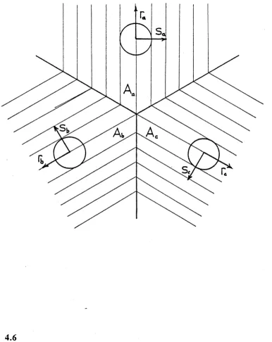
written with respect to the chosen co-ordinates and are given in (2-3), whereas the angle between the (x,y) field decomposition axes and the local optical axes (a,b), say, as shown in Fig. 2.6(b) . If the waveguide is isotropic, or if vector decomposition can be effected using one set of local optical axes throughout, then the right hand sides of (2-30b) and (2-30c) vanish and the two scalar equations de-couple. If the optical axes physically vary over regions of the cross-section where non-zero fields are present, then (2-30b) and (2-30c) must be physically coupled. Thus non-LP modes may arise from a scalar analysis alone, in weakly- anisotropic waveguides with non-uniform optical axes.
33
FIG. 2.6
( c h
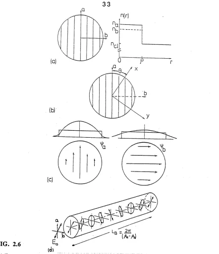
(a) Example of a simple anisotropic fibre - a step-profile circular core of index na for and
nb for a'PoIarized and b-polarized light, respectively, surrounded by an infinite isotropic cladding of index nci . The fibre is weakly-anisotropic when 5 ab « 1 and
weakly-guiding when A « 1, and may be analysed as two independent isotropic fibres, ^ab A are defined in (2-28) and (2-4) respectively.
(b) Any pair of orthogonal axes may be used for field decomposition, not necessarily the optical axes, without changing the physics itself.
(c) Scalar fields, \{/a and \\fb , for the two orthogonally polarized modes may differ, but only negligibly in weakly anisotropic fibres.
[image:44.565.74.516.36.547.2]radius and same uniform cladding index n c, . The two orthogonally polarized solutions of (2-30) are therefore independent modes :
Ea(x,y ,z) = ea(x,y)elßlZ = ä\|/a(x,y)eßiZ (2-3 la)
Eh(x,y,z) = eb(x,y)e ßb = 6\|/b(x,y)e ßb (2-31b)
where ßa and ßb are the propagation constants for the solutions \|/a(x,y) and \|/b(x,y) of the isotropic scalar wave equations for the equivalent fibres. In an arbitrary anisotropic waveguide, \|/a differs from \{/b, as shown in Fig. 2.6(c). If the fibre is only
in
weakly-anisotropic, as in cases treatec^this thesis, the spatial field distribution is essentially the same for both polarizations.
Launching light into the fibre at an angle to the optical axes excites both of these modes, which will then propagate independently, and periodically fall into and out of phase. Periodic beating of the polarization state from its initial state to intermediate elliptical states and back takes place on a length scale LB = 2tt/ lßa - ßb I, as shown in Fig. 2.6(d). The more anisotropic the fibre is, the shorter is this so-called "birefringent beat length". In section 2.4, we show that LB varies inversely with 8 to lowest order.
2.3.10 Polarization effects in anisotropic waveguides
Coupling between the orthogonal components of the transverse electric and magnetic fields is caused by terms on both the left and right sides of (2-29), unlike the isotropic vector wave equation (2-13) in which only the right side contains coupling terms. Even in weakly-guiding anisotropic waveguides, where geometric birefringence would be negligible in the isotropic limit, material birefringence still appears on both sides of the equation.
3 5
geometric contributions, in that they are closely associated with field and index gradients at boundaries, albeit in a skew sense.
The anisotropy also appears on the left side in the index tensor, which couples the components, since nt2 et is not parallel to et unless et is polarized along the optical axes
everywhere. This is not generally the case, especially if the optical axes themselves vary with position in the cross-section, as in the birefringent couplers to be examined in Chapter 5.
Thus, the coupling between transverse field components is more complex in the anisotropic waveguide generally, with three contributing factors :
1. Material anisotropy - axes and magnitude, 2. Geometry of the index boundaries,
3. Geometry of the anisotropic region.
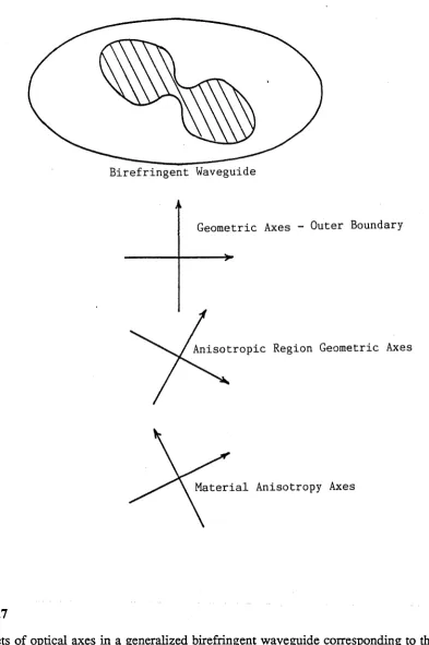
Of these, the first is by far the most important if it exists at all. These contributions may arise in the same sense, if the axes are co-incident, but this need not be so. Fig. 2.7 shows a more complicated possibility - an elliptical waveguide with a dumbell-shaped anisotropic region. The optical axes of the system, namely the birefringent axes, the ellipse axes and the dumbell axes, all differ. An inseparable fourth effect, not mentioned, is the shape of the field itself, which also appears in the terms on the right of (2-29). Consistent solutions for the vector modes depend on the birefringence contributions from the right side of (2-29), which depend in turn on the fields and so on. Thus, overall birefringence will differ from mode to mode.
Polarization coupling between two scalar modes due to the small terms on the right hand side of (2-29a) is only observable if two conditions occur:
1. The material cross-coupling terms on the right of (2-30) are smaller than or
comparable to those on the right of (2-29a), and
36
Birefringent Waveguide
Geometric Axes - Outer Boundary
Anisotropic Region Geometric Axes
Material Anisotropy Axes
FIG . 2.7
[image:47.565.106.499.63.654.2]37
Condition 1 can only occur in nearly-isotropic waveguides, or when the optical axes of the anisotropic waveguide are almost uniform throughout, and field decomposition is performed along the optical axes, otherwise the material cross-coupling terms on the right of (2-30b,c) will dominate. Condition 2 is analagous to the scalar degeneracy requirement for hybrid vector modes in an isotropic waveguide - the scalar modes must be almost degenerate, otherwise the scalar split will be much larger than the form birefringence coupling the modes, and the modes will be determined by the scalar equation (2-30) alone.
To satisfy both conditions simultaneously requires an almost-isotropic waveguide with almost-uniform optical axes, in which case the isotropic analysis usually suffices. From now on, therefore, we ignore the remaining terms on the right hand side of (2-29a), since they only give rise to tiny corrections to the scalar fields and propagation constants, and we analyse weakly-guiding weakly-anisotropic waveguides using the scalar equation (2-30).
2 .4 THE PERTURBATION APPROACH 2.4.0 Perturbation results in the scalar regime
Optical fibre couplers which function by evanescent cross-talk between the consitituent fibre cores, and birefringent fibres which exhibit periodic length variations in the polarization state, both experience beating between two or more of their normal modes. This beating takes place on length scales much greater than the optical wavelength, and is*a very slow variation in the optical sense, resulting from a very small relative difference between the propagation constants of the normal modes involved. In a sense, the main effect of one fibre on another in an evanescent coupler, or the effect of anisotropy in a birefringent fibre is to slightly perturb the propagation constants of one or more of the normal modes from some "unperturbed value".
isolating the fibres in the lim iting case, indicating that the unperturbed propagation constants are those o f the individual fibres. It is intuitive that, in weakly-guiding cases, the corrections to the unperturbed propagation constants are obtainable using a first-order
scalar analysis.
Because the perturbations are very weak, we may approximate the normal modes o f perturbed w eakly-guiding w aveguides by com binations o f the unperturbed scalar m odes, since any field errors introduced by this approxim ation remain small along the w aveguide. The correct com binations are deduced from consistency conditions arising from the perturbation analysis. Thus, the only required corrections to the scalar results for the unperturbed w aveguide involve the propagation constants, since the resulting cum ulative phase differences along the fibre are the principal physical feature of the perturbed waveguide.
Consider, therefore, an arbitrary w eakly-guiding w aveguide, e.g. a coupler, which is characterized by an index profile n(x,y), and supports a normal mode whose transverse electric and magnetic fields may be written in the separable form o f (2-6):
The spatial variation o f e(x,y) and h(x,y) can be represented by \|/(x,y), where \y(x,y) is a solution of the scalar wave equation for the perturbed waveguide:
The profile n2(x,y) differs little from the unperturbed profile n2 (x,y) of a weakly-guiding waveguide whose transverse fields may be written in the form :
E(x,y,z) = e(x,y)elßz ; H(x,y,z)= h(x,y)elßz (2-32)
(V2 + k2n2(x,y) - ß2) y(x,y) = 0 (2-33)
E(x,y,z) = e(x,y)elßz ; H(x,y,z) = h(x,y)elßz (2-34)
39
(V“ + k V (x ,y ) - ß ) y(x,y) = 0 (2-35)
where ß is the unperturbed propagation constant.
If we multiply (2-33) by \j7 and (2-35) by \ | / , subtract, integrate the result over the infinite cross-section, AM, and use Green's theorem around the infinite outer boundary, we obtain a relationship between the known and unknown propagation constants in terms o f the known and unknown scalar fields :
where k = l i z f k as usual. Evaluation o f (2-36) requires the unknown field distribution,
\\r. Hence, this m ethod is only suitable if \\r (x,y) can be expressed in terms of one or more known m ode fields \|/(x,y) o f the unperturbed system(s), or if it can be "guessed" by some other technique (see below).
A ssum ing w eak guidance and w eak perturbations, we may m ake several simplifying assumptions. First, we know that ß and ß are nearly identical, so
where nco is the assumed maximum value of the refractive index in both the perturbed and unperturbed waveguides. Also, weak-guidance tells us :
(2-36)
ß2 - ß2 = 2knco (ß - ß) (2-37a)
(2-37b)
so that (2-36) becomes
This is a general expression, accounting for perturbed fields which differ markedly from the unperturbed fields, e.g. in an evanescent coupler, where the perturbed fields are constructed from combinations of unperturbed scalar modes of two or more fibres. If a single fibre is subject to a slight perturbation, then \j/ is almost the same as the unperturbed field \j7 , so (2-38) gives:
ß - ß s k J ( n - n ) v 2 d A / j V d A (2-39)
In this case, if the perturbation is a uniform change, 5n, in refractive index over a finite area, Ap , say, then from (2-10), the fraction, riAp , of the total power in the unperturbed mode propagating in this region is given by
iiAp= [ v d A / J / f d A (240)
Ap A»
Hence, for this type of perturbation, (2-39) gives
ß - ß = k r | Ap5n (241)
The change in the propagation constant varies to first order with the change in refractive index over the perturbation region, in such cases. This result applies to weakly-anisotropic fibres discussed below in subsection 2.4.2.
Several techniques exist for solving (2-36), (2-38) and (2-39) in perturbed waveguides. The simplest and most intuitive method is to deduce the unknown modes from symmetry principles, given a general idea of what the mode must look like. This technique applies to symmetric evanescent couplers, such as the six-port couplers treated in the following chapter. Care is needed with this approach, as there is no guarantee that the unknown form inserted into (2-38) is in fact the correct one, since a value for ß - ß will