Abstract— PISim is a new piece of software for process control
teaching and learning. The software allows control structures to be designed on a piping and instrumentation diagram and, as the structure is created, the software automatically spawns device mimics representing the real physical HMIs that operators would see. These can be placed on a control panel and a simulation of the process can be operated using the student’s control scheme. The use of PISim in an introductory control class at Strathclyde University is described and student feedback is presented.
I. INTRODUCTION
Dynamic simulation has been used in control teaching for many years. Even before the early days of microcomputer simulators some brave souls were teaching control using a mainframe based SCADA system over a dedicated land-line [1].
Nowadays there is unlikely to be a chemical engineering process control class or training situation that does not make some use of dynamic simulation. The most common types of these simulators can be grouped into three categories:
1. Block-based dynamic simulation languages, e.g. Matlab/Simulink; VisSim; Scicos.
2. Process unit based simulators, e.g. Aspen Dynamic; CHEMCAD; DYNSIM.
3. Fixed simulation exercises, e.g. Hyperion; GSE Systems; TCS Simulations.
The block-based systems are probably the most flexible of the three as they essentially only supply a user interface and the integration algorithms. It is up to the user to formulate and encode the continuity balances and other equations that are required to produce a model. This is great when the object is to teach students about dynamic simulation but it is less useful when trying to illustrate full-scale plant control.
The process unit simulators are industrial grade systems and are used to perform simulation tasks in real situations. They are very powerful but that power comes at the cost of a significant learning curve. Classes using these process unit simulators often turn into training programmes on the software itself, rather than on the control principles that were the original educational aim.
Fixed simulator exercises, where the simulation is of a fixed plant and controller configuration, are often used in
*Bruce Postlethwaite is with the Department of Chemical Engineering, University of Strathclyde, Montrose St, Glasgow, Scotland, UK. email: [email protected]
industrial training but also find their way into the classroom [2, 3]. These simulators will usually have a user interface that is very similar (or the same, in the case of operator training simulators) to that which the operators would see on a production plant. The downside is that the fixed process and controller structure limit their usefulness for anything other than the simplest of control classes.
At the University of Strathclyde, we have used all of three of the simulation categories at one time or another. We were one of the group of UK Universities involved in the IBM ACS experiment in the 1980s, and we’ve created in-house ‘operator station’ type simulators using Lab-view and other software. We have attempted to use Aspen-Dynamics in a process control design class (as an adjunct to our process design), but gave up after a couple of academic years when we found that all the student questions we were getting concerned the software and not the design process. Most recently we have been using block-oriented simulators: VisSim for a number of years; and Simulink for the last four. When teaching a subject it is often very difficult to get a student’s perspective on the material that is being presented. When producing dynamic simulation material for a class it is easy to forget that the way in which we perceive the material is from the point of view of an expert. We already
understand what is being represented and have no problem in dealing with the abstractions that different software systems present to us.
Student see things very differently and find it difficult to link abstractions with real-world systems. Although this seems obvious it is easy to forget, and it was a letter from a former student complaining that he hadn’t been taught about P&IDs (pipeline and instrumentation diagrams) that
triggered a bit of reflection for me. P&IDs are one of the primary design documents for control in the chemical and process industries and the student definitely had been taught about them. However after thinking about this and talking to some current students I could see that he had actually spent most of his simulation time in the control classes looking at Simulink blocks, which look very different to a P&ID.
Further thinking about this led me back towards software that we had used for teaching in the late 1980’s-early 1990’s called UCONLINE/SIGNAL.
The use of simulation in chemical process control learning and the
development of PISim
II. UCONLINE AND SIGNAL
UCONLINE was a DOS-based program for control teaching initially developed by Prof. Alan Foss and some of his students at UC Berkeley [4]. UCONLINE was software that was specifically designed for teaching and learning. It allowed learners to take a pre-coded process model and then add a control system over the top. Once the control system was complete the whole thing, process plus control system, could be run as a simulation and produce trends and other control displays for students to look at.
The main intention of UCONLINE was to allow students to investigate multi-loop configurations, but it turned out to be really useful for illustrating introductory concepts such as basic process dynamics and simple loop configuration too. We adopted UCONLINE at Strathclyde as our main teaching software for control and used it for seven years, with students in the basic control class doing a one hour simulation class every week over a ten week period.
Although, as instructors, we loved UCONLINE it must have been pretty painful for our students. In common with all DOS-based programs of the time UCONLINE made use of command lines such as:
VD, DVR, ASUM, D*
ASUM, AL=+, V1=DM, V2=LM, A0=1.0, A1=1.0, etc (this is part of an example from Alan’s paper showing how easy it is to use UCONLINE!)
Once you got used to it, it was fine, but the interface is not something that today’s students would be happy using. Alan did recognize that the UCONLINE interface could be a bit cryptic and in his last years at Berkeley had started work on SIGNAL [5].
SIGNAL was a preprocessor for UCONLINE. Instead of configuring the control system using difficult to understand command lines students could instead draw it onto a P&ID-like representation of the process. Once the student was happy with the configuration SIGNAL would generate the necessary UCONLINE configuration commands to produce the system. These could then be loaded into UCONLINE and the control system tested.
SIGNAL was a great idea, and it kind of worked, but it was cumbersome and we never used it at Strathclyde. When Alan retired from Berkeley there was no-one to take over the development of UCONLINE/SIGNAL and the software became unsupported and quickly went out of date as the new Windows operating systems came along. In many ways the team at Berkeley was too far ahead of its time as the operating systems and hardware of the early 1990’s weren’t powerful enough to let them adequately realize their vision.
III. SPECIFICATION OF PISIM
Memories of UCONLINE/SIGNAL, and the realization that students were not engaging properly with simulation content in the software that was currently used led to me rethinking the UCONLINE vision in terms of modern hardware and operating systems. I decided that a good system would be able to:
Represent the process in a standard P&ID and allow control and instrumentation systems to be configured on top of this diagram using standard P&ID symbols. Automatically generate on-screen devices that mimicked the HMI of devices being specified by the P&ID, e.g. indicators represented by a LED display or dial, controllers represented by a faceplate.
Allow the on-screen devices to be combined onto backgrounds to allow the creation of control panels or simulated SCADA displays. The idea here was to include consideration of the plant HMI as part of the control system design.
Allow the whole system to be simulated easily and directly from the main window with the on-screen devices updating in real or accelerated time.
I discussed this loose specification with some friends (who prefer to remain anonymous) who had worked with me on a previous software project and the PISim (P&I Simulator) development team was born.
IV. PISIM DEVELOPMENT
The programming team had experience in a variety of languages including C++ and Visual Basic. We took some time to think about what an appropriate environment would be for this project, and ended up picking Xojo. Xojo is very similar to the old (pre-NET) Visual Basic in terms of the ease of producing basic user interfaces, but is much more strongly object-oriented. Xojo also has the advantage that it is designed for cross-platform development and so the same code for a Windows application should, in theory, be capable of generating OS X and Linux programs.
We have stuck to object-oriented programming throughout the project. Since all of us came from a FORTRAN background (we are all a bit old) this went a little against the grain, but has paid dividends in speeding the programming process.
[image:2.612.318.547.553.733.2]The initial test version of PISim was ready in July 2015 (about fourteen months after project start). The program went out to beta testers in August, and was used ‘live’ for
the first time in the Sept-Dec 2015 academic session in an introductory control class with around 130 students.
V. PISIM USER INTEFACE
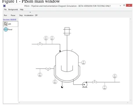
The main window for PISim (Figure 1) includes some menus to load and save simulation configurations and to add backgrounds to allow control panels to be created.
Underneath the menu bar are the simulation control buttons. The simulation is completely controlled using these buttons. There are no other menus or options for the learner to worry about.
On the left of the window is the tools palette, which is rather sparse at the moment as we currently only have a bubble for discrete, panel-mounted, devices. Additional devices such as shared display and computational units will be added in the future.
The main part of the window contains the basic P&ID for the process. Before a control system is configured the P&ID only contains transmitters and control valves. These symbols have hotspots that allow connections to be made to and from the process simulation when instrumentation is added to the diagram. A configured control scheme is shown in Figure 2. Adding components simply involves selecting the
appropriate tool and then clicking on the diagram. The components are configured by right-clicking, which brings up a configuration menu. Components are connected to the process by clicking on an output port and dragging the signal line to the desired input.
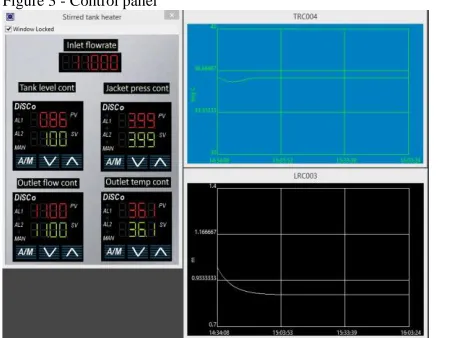
Part of the component configuration involves selecting what sort of devices (i.e. indicator, recorder, controller and alarms) are represented by the component. When this is done PISim produces an on-screen representation of each device. These devices initially are loaded into their own windows but can easily be transferred onto backgrounds that represent a control panel. The backgrounds can be loaded with any background image that the user desires. Figure 3 shows a
control panel that was produced from the Figure 2 configuration.
All of the devices are ‘active’ and present information from the simulation and allow interaction (e.g. by responding to button presses).
VI. USE OF PISIM IN AN INTRODUCTORY CONTROL CLASS PISim was used on the introductory control class for chemical engineers at Strathclyde University last fall (2015). The students had some basic introductions to control integrated into classes in earlier years but this year four class (Scottish engineering undergraduate degrees are normally five year courses) was the first formal control teaching they had.
Our control class was updated two years ago to bring it in line with the IChemE (the UK Institution of Chemical Engineers) model syllabus for control teaching. This model syllabus was introduced after industry concerns that
‘academic’ control and the needs of industry were diverging. This is not a phenomenon that is unique to the UK, and Edgar et al [6] describe a very similar situation in the USA. The control class is split into six blocks each of two-week duration (the semester lasts for twelve weeks). In each block there are three hours of fairly standard lecture content (that is recorded and available to students after class), an hour of guided individual problem solving, and two hours of group workshops. The workshops are used to introduce students to slight more involved problems than they have to deal with in the individual sessions.
The topics covered in the six blocks are:
1. Introduction to control, basic instruments, control valves and communication.
2. Diagrams and responses. P&IDs are covered in some depth and some typical process responses (integrating, self-regulating and unstable) are introduced
[image:3.612.61.293.537.730.2] [image:3.612.321.558.557.726.2]3. Modelling and Laplace transforms. Dynamic modelling, deviation variables, linearization, transfer Figure 2 - a configured control system in PISim
functions and solution of first-order response to step changes.
4. PID control. Algorithms, control system analysis and tuning
5. Control system design. Multi-loop systems, material balance control, control system architecture.
6. Safety Instrumented Systems including cause and effect diagrams (taught by a lecturer from industry). In addition to formal class time students are also expected to carry out work in their own time. One of these activities uses Moodle lessons (Moodle is the on-line learning system used at Strathclyde) to guide students through simulation exercises using PISim. The exercises are tied very closely to the content of the block they are in, and don’t require a special ‘PISim training’ module. Instead the use of the software is introduced gradually in a way that is integrated with the rest of the class material. Each of the Moodle lessons takes a student one to two hours to complete. We’ve installed PISim on computers in our Departmental computing labs, but have also made it available for students to install in their own machines.
The content of the Moodle lessons for each block is: 1. Introduction to control. Students are presented with a
pre-configured control system with the devices arranged on a control panel. They get to play with servo control and disturbance rejection (and also see the difference between AUTO and MANUAL controller modes). They also get a chance to think about inputs and outputs from a control (rather than chemical engineering) perspective.
2. Diagrams and responses. The students learn about the application of direct and reverse acting controllers. They get to try step inputs on pure integrating and on first and higher order processes. They explore various possible reasons for instability. Finally they are asked to estimate approximate gains and time constants from a process dynamic response.
3. Modelling and Laplace transforms. This is the most mathematical part of the course, but in the simulation lesson I’ve chosen to explore the limits of linearized models of non-linear processes. The students are asked to estimate model parameters (gains and time constants) for a process around a particular operating point, and then to make some small input changes to test their estimates. They are then asked to make much bigger changes to see if their model still works. 4. PID controllers. In the simulation work the students configure a PID loop and look at the different controller modes, and the effects of changing the algorithm. They tune their controller using two (or more) different methods. They also do a bit of analysis of P-only and I-only controlled systems and compare their predictions with simulation results. 5. Control system design. Students configure a
multi-loop control system, paying attention to mass balance control and to the need to meet operational objectives. They tune and test the control system.
6. Safety Instrumented Systems. At the moment PISim lacks the capability to handle discrete signals and so there is no simulation content for this block. We will be adding discrete signal processing in the near future.
VII. FEEDBACK FROM TESTERS
The software was trialed before its use in class by a group of testers recruited via the LinkedIn process control group. A total of 24 participants signed up for the test, 18 downloaded the test software, but only 4 completed the final
questionnaire.
Although the level of response was a little disappointing we did get very useful information from those who replied. In particular:
Most of the testers found that making connections between elements was a bit awkward.
Fancy display elements such as SCADA emulation or dial displays were low down in the testers’ wish lists.
Computational elements (hi/lo select, multiply, etc.) were considered to be important things that needed to be added.
From the feedback we felt that there was a need to add explicit support for instructional material. Some of the testers seemed confused about what PISim’s purpose actually was.
The testers reported no significant bugs or crashes while using PISim and so I considered it worthwhile going ahead with a test in the classroom. The software was used during the Fall (September-December) semester 2015 in our introductory control class. The class is taken by full-time students (114 in 2015) and also by students taking our distance learning degree (9 students).
Feedback from students was gathered via an on-line questionnaire. The questionnaire consisted of 15 questions with a mix of general questions about the course and a number of specifically PISim questions. Ninety of the students registered for the class completed the questionnaire.
The response of students to the PISim interactive material in the class was overwhelmingly positive, with many students including it in their ‘favorite parts of the class’ freeform list in the general part of the questionnaire. Some of the students’ positive comments were:
Working with PISim really helped me understand the course.
The PISim exercises and assessments were very helpful in giving me an understanding of how the maths is applied on a real life/practical scale. The PISim part of the course was good and gave
insight on how control fits into a P&ID.
required for the interactive lessons, and stress due to the nature of on-line quizzes.
However a number of students reported problems with the connection and disconnection of the elements in the P&ID. This is a problem that was also raised by the industry based testers and seems to be due to small hotspot areas and insufficient visual cueing on where the hotspots are.
There were also complaints that there was no help available for PISim and that lessons had to be repeated if a student forgot how to do something (e.g. to break a connection). I was surprised by this as I made sure that the PISim version distributed to students included a help file, accessed from the usual ‘Help’ item on application menu-bar. On talking to the students it seemed that most of them hadn’t noticed that it was there and instead immediately ‘Googled’ for PISim help. It is clear that we need to add a more internet aware help system, and the students have suggested short video walkthroughs rather than textual descriptions.
There were also a number of comments about bugs that occurred during the interactive lessons. It turns out that these bugs were mainly in the Moodle lessons rather than in PISim itself. Moodle is an open-source system that is maintained by the community. The lesson module seems to be an area where development and support has been a bit lacking and students complained of marks not being recorded and difficulty in using the interface. The lesson module also restricted the sort of things we could ask students to do. The only user interaction with the lesson was pressing a button to move through it and answering quiz questions. It was very difficult to ask a student to do something to PISim in a lesson and be sure that they had done it correctly.
The class performed statistically significantly better overall than in the previous year (average of 54.4% compared to 49% in 2014/15). The questions in the final exam were similar in both years and the 2015/16 paper did not contain material specifically related to PISim. Any performance boost caused by PISim would have been ‘splash’ on other aspects of the class from the interactive lessons.
Although the raw statistics show a significant
improvement it is of course impossible to say that the two exam papers (2014/15 and 2015/16) and the class
assignments were of exactly the same difficulty. What was clear was that the majority of students were more engaged with the class material during the semester.
VIII. FUTURE DEVELOPMENT
The response from the trials clearly showed a need for a learning system that is much more integrated with PISim, and this is where our efforts are currently focused. We had initially considered a script-based system but we quickly realized that this would involve reinventing the wheel. Rather than spend time developing methods for presenting slides, videos, quizzes, etcetera, we are working on a system that schedules material within a lesson and then spawns
other software (such as Powerpoint, PDF readers, etc.) to handle the standard lesson tasks.
We will be concentrating on methods to assist students and instructors in getting the most out of the PISim
experience. We are currently working on two lesson tools: a configuration checker, and a control system tester.
The configuration checker loads a ‘good’ control configuration for a particular system that has been prepared by the instructor. When a student is undertaking a lesson and completes their own configuration they can then check this against the instructor configuration by pressing a button. The checker tool can assign scores for the things a student has got correct and can offer retries with adjusted scores. The tool also has a hint facility (that can be switched on or off by the instructor when they create the lesson) that provides tips for students about things they might have got wrong.
The control system tester allows an instructor to setup a predefined sequence of changes in a simulation’s
disturbance variable. This sequence can be run by the student by pressing a button and the tool records the ISE (or IAE, or ITAE) of instructor selected control variables over the period of the test. This information is then presented to the student. This allows exercises to be created where the student has to develop a control system that meets an assortment of performance goals.
Another point that came up during testing, particularly with industrial users, was the range of PISim components available. The component list in PISim is currently very limited with only discrete panel mounted devices being represented. We plan to add computational elements (e.g. max, min, sum, mul, etc.) this summer, and still (despite the lack of enthusiasm from our industrial testers!) plan to add SCADA interface simulators to allow our control displays to look a bit more ‘modern’.
An area for future development is to expand the range of simulations available. Currently PISim has three functioning simulations: a two tank, non-interacting level system; a steam jacketed stirred tank heater; and an exothermic continuous stirred tank reactor. All of the simulations can be adjusted by modifying parameters, providing a large range of basic process models. These basic processes are very useful in supporting introductory control classes but are of limited use for more advanced work. In the immediate future we plan to add a binary distillation column but later will be adding more complex processes such as the Williams-Otto plant [7]. Eventually we hope to work with end-users to produce models suitable for particular industry groups.
REFERENCES
[1] P.E. Sawyer, P.L.Yue, S.Bolton, R.G.Hill and R.M.Kerr, “The role of IBM’s Advanced Control System in enhancing undergraduate education in Chemical Engineering”, Proc. World Congress III of
Chemical Engineering, Tokyo, 1986.
[2] R.Sreenivasan, W.S.Levine and G.W. Rubloff, “Some experiments in dynamic-simulator-based control education’, Proc. American Control
Conference, San Diego, 1999.
fault-tolerant fraction control”, Procedia – Social and Behavioral Sciences, vol. 46, 2012, pp 1919-1923
[4] A.S. Foss, “UCONLINE Berkeley’s multiloop computer control program”, Chemical Engineering Education, Summer 1987, pp 122-156.
[5] A.S. Foss and P.J. Goodeve, “Inventing multiloop control systems in a jiffy with interactive graphics”, Chemical Engineering Education, Summer 1991, pp 126-131.
[6] T.F. Edgar, B.A. Ogunnaike, J.J. Downs, K.R.Muske and B.W. Bequette, “Renovating the undergraduate process control course”,
Computers and Chemical Engineering, vol. 30, 2006, pp 1749-1762