technologies
James P. McGilligan, Paul F.
Griffi
n, Rachel Elvin, Stuart J. Ingleby, Erling Riis & Aidan S.
Arnold
We have laser cooled 3 × 10⁶ 87Rb atoms to 3 μK in a micro-fabricated grating magneto-optical trap (GMOT), enabling future mass-deployment in highly accurate compact quantum sensors. We magnetically trap the atoms, and use Larmor spin precession for magnetic sensing in the vicinity of the atomic sample. Finally, we demonstrate an array of magneto-optical traps with a single laser beam, which will be utilised for future cold atom gradiometry.
Laser cooling has led to profound advances in the field of metrology due to the increased interrogation times gained from the low velocity ensembles1, 2. The longer interrogation times correspond to narrower transition
res-onances that have proven critical to the field of quantum sensors. The issue hindering the use of cold atoms as the basis of a portable quantum device is the large spatial scale of the apparatus3–5. Significant efforts have been made
in recent years to overcome this constraint by developing a compact technology that facilitates ultra-cold atomic ensembles as a portable sensing device6.
Attempts to achieve a scalable cooling apparatus have been demonstrated in the past in the form of the pyr-amid magneto-optical trap, PMOT7–9. This consists of a structure with four highly reflective walls, angled to
overlap the reflected beams with the incident light. The device needs to be maintained in the vacuum, due to the MOT forming within the pyramid volume. Further difficulties arise when imaging these atoms due to optical restrictions caused by the pyramid geometry. An alternative tetrahedral mirror pyramid geometry10 ameliorates
all negative features of the standard PMOT.
In this paper we build upon our work with the grating magneto-optical trap, GMOT11–14, and show it is a
via-ble platform for compact quantum sensing by generating a truly ultra-cold atomic sample with a micro-fabricated chip. This study also focusses on magnetically trapping a cold sample for measurement of the background Rb pressure present in the vacuum chamber. Furthermore, we utilise Larmor spin precession for magnetometry in order to null stray static and gradient fields in the lab environment. Finally, we demonstrate an array of cold atoms generated above a diffractive optic with a single laser, with an outlook to demonstrating a compact, cold atom gradiometer.
The grating magneto-optical trap
The GMOT cools atoms by a balanced radiation pressure between a single incident laser beam and the diffracted orders generated from the grating surface. Recent investigations of physical geometry have aimed at the optimi-sation of the diffractive optics for generation of a balanced radiation pressure, with the current conclusion that a 1200 nm period of 60:40 duty cycle in a triangular geometry performs best when used outside the vacuum12. In
addition to the laser alignment and intensity balance controlled by the diffractive optic12, the critical parameter to
achieve sub-Doppler temperature is the magnetic field.
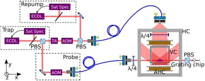
The GMOT set-up used here is illustrated in Fig. 1. The trapping and probing light is derived from a sin-gle external cavity diode laser, ECDL, to address the D2 transitions of 87Rb. This laser is locked using saturated absorption spectroscopy and then divided into two separate beams for cooling and pump/probing. The cooling arm is fed into a tapered amplifier (ThorLabs TPA780P20) to provide up to ≈300 mW of trap light after fiber cou-pling. This cooling light is then red detuned by 2Γ, i.e. −12 MHz from the F= 2 to F′= 3 transition via an AOM and combined with re-pumping light on a PBS, before being fibre coupled into the chamber.
The triangular grating is mounted externally from the vacuum system, held horizontally under the glass chamber with the incident light fibre coupled in via a compact tube, which collimates to a 1/e2 diameter of 2 cm and circularly polarises with a quarter wave-plate. Two anti-Helmholtz coils of diameter 12 cm are symmetri-cally aligned above and below the plane of the grating chip to produce 15 G/cm axial magnetic gradient, with a 25 × 25 × 12 cm Helmholtz coil box used to null stray magnetic fields from the lab environment. Cancellation
Department of Physics, SUPA, University of Strathclyde, Glasgow, G4 0NG, UK. Correspondence and requests for materials should be addressed to A.S.A. (email: [email protected])
of these stray magnetic fields has proven critical in achieving a lower temperature optical molasses, resulting in the vacuum system being redesigned with a 2 L/s ion pump to reduce gradient fields in the region of the atomic sample.
The experimental procedure involved a 400 ms MOT load directly from background vapour with incident trap intensity 10 mW/cm2, then 10 ms of sub-Doppler cooling in a three-stage molasses. This involved detuning the trap light by 30 MHz and 60 MHz and then halving the intensity in the final stage to achieve temperatures as low as 3.0 ± 0.7 μK, as measured from time of flight imaging15. This ultra cold ensemble is an ideal starting point for
experiments requiring long measurement times and low atomic densities, such as atomic clocks.
Pressure gauge in a compact apparatus.
To achieve a low temperature molasses in a compact apparatus, we designed our vacuum system with scalability and simplicity in mind, such that a single Rb dispensing getter is used in conjunction with a 2 L/s ion pump (Titan ion pump - Gamma Vacuum). To attain a measurement of the vacuum background pressure at the MOT, we use the relation of the magnetic trap lifetime, τ, to the back-ground Rb pressure in the chamber, P, as demonstrated by Monroe16. The author estimated a lifetime of 10 s for abackground pressure at 7 × 10⁻¹⁰ mbar, with the dominant loss contributor being the van-der Waals interaction between the trapped and thermal background atoms. This relation has been utilised in other literature for back-ground pressure measurements at the atoms, each reaching a similar number17, 18.
The atoms will be magnetically trapped if the magnetic force is larger than that of gravity, where the magnetic force along the gravity direction z can be described mathematically by,
µ = −
F g m dB
dz, (1)
z F B F
where gF is the Lande g-factor, μB is the Bohr magneton, B the magnetic field magnitude and mF is the non-degenerate level of the total angular momentum state. This force can then be used to trap weak-field-seeking atoms if Fz is greater than gravity.
The experimental procedure to achieve this begins by trapping the atoms in a quadrupole field, with an axial gradient 15 G/cm. At the end of the molasses sequence the trapping light was turned off and a short optical pump-ing pulse applied to drive the atoms into the weak-field-seekpump-ing F= 2, mF= 2 state. The gradient field from the quadrupole coils was afterwards increased to 50 G/cm, whilst florescence images were taken for a varied time of flight. This enabled the trapped atom number to be described as a function of time, as seen in Fig. 2.
The experimental data points were fit with an exponential decay of the form, N exp (−t/τ), where N is the ini-tial atom number and τ is the 1/e magnetic trap lifetime, determined as 180 ± 10 ms. If we use this τ to determine the background Rb pressure in the vacuum system, using the relation introduced earlier, we estimate a pressure of 4 × 10⁻⁸ mbar. This pressure is primarily due to the low pumping rate of the scaled down ion pump in an unbaked chamber. However, a 10−8 mbar pressure is achievable in other systems, where the ion pump has been made redundant in place for specialised micro-fabricated vapour cells with low-He-permeation glass19. Such apparatus
would enable future reduction of the vacuum system volume for an unambiguously compact device.
Magnetic sensing for a low temperature molasses.
Optically pumped atomic magnetometers work from the principle of coherent spin precession of a polarised atomic species in the presence of a magnetic field. Larmor spin precession is based on atomic magnetic moments interaction with a local magnetic field, aided by the optical pumping of atoms with near resonant light into a non-degenerate Zeeman level of the ground state via an excited state transition. Once in the stretched state, the angular momentum vector, F, will precess about the axis of an applied magnetic field, B, at the Larmor frequency,ωL= −γB , (2)
Figure 1. Schematic of the grating MOT experimental set-up. ECDL: External cavity diode laser, Sat Spec:
[image:2.595.157.552.46.202.2]where ωL is the Larmor frequency, γ =−2egmF is the gyromagnetic ratio of the atom, e is the electron charge and m is the electron mass.
The precession of F around B changes the optical absorption and dispersion properties of the atomic ensemble by passing in and out of resonance with the incident polarised electric field. Thus, the precession can be observed as a damped oscillation in the optical absorption and dispersion, measured using a polariser and detector, to give a direct measurement of |B|20–23.
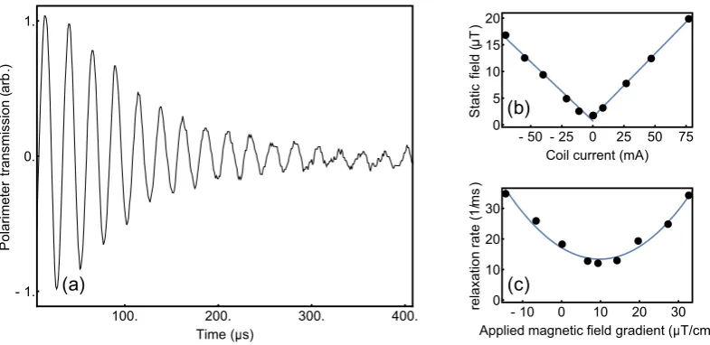
Here we measure Larmor precession in an un-shielded grating magneto-optical trap to null stray static fields and reduce the level of gradient fields present during our molasses. The set-up, Fig. 1, uses the same laser source for cooling and probing by splitting the beam into two optical arms. The pump/probe arm is tuned into resonance with the F= 2 to F′= 3 level using an AOM. The technique chosen was to use an on-resonant pumping beam, such that a constant intensity beam of 0.68 mW/cm2 and duration of 10 μs would resonantly pump the atoms with circular light into the stretched state. A 10 Γ detuning was then introduced by electronically offsetting the lock-point of the spectroscopy signal for a far off-resonant probe beam. The atomic rotation around an applied magnetic field changes the probing electric field polarisation, allowing a more sensitive detection to be made using a polariser for increased signal-to-noise, as seen in Fig. 3(a). This experimental procedure was run in con-junction with a Schmitt trigger from the AC mains in order to reduce AC magnetic field noise by making the magnetic measurement at the same point of the 50 Hz cycle each time.
The precession data is fit with A exp (−t/τ) sin (2πωLt+φ), where A is the initial signal amplitude, τ is the decay time and φ is the phase. The Larmor frequency, ωL is directly related to |B| through Eqn. 2, allowing direct correlation of shim current values to the static field in the vicinity of the atomic ensemble. Figure 3(b) illustrates the measurement of the static magnetic field value as a function of the Helmholtz coil current to null the stray fields. This was used on both perpendicular axes to bring the measured field down to the level of the lab noise floor, ~800 nT.
Figure 2. Atom number in the magnetic trap as a function of the ballistic drop time. The blue line indicates an
exponential fit to determine a 1/e trap lifetime of 180 ± 10 ms.
Figure 3. (a) Larmor precession measured from the GMOT. (b) The static field determined from the Larmor
[image:3.595.156.363.46.184.2] [image:3.595.156.549.233.424.2]Sensitivity to gradient field components is obtained through the transverse relaxation rate in the ground state coherence, γ= 1/τ, which is directly related to the total magnetic field gradient through γ=a|∇B|2+γ
0, where
a is the coefficient describing the sensitivity to the magnetic field gradient and γ0 is the relaxation rate in the absence of gradient fields24. The measured transverse relaxation rates in the ground state coherence are visible
in Fig. 3(c), where the parameter γ is plotted as a function of the difference current between the Helmholtz pair. When applying gradient cancellation on the perpendicular axes by making first order corrections to d|B|/dz and
d|B|/dy we could improve the transverse decay time from 30 μs to 100 μs. A transverse decay time of 100 μs was the best achievable in our unshielded set-up.
With the magnetic gradient fields nulled as well as possible, the temperature in the molasses was then studied as a function of the applied static magnetic field, to demonstrate the necessity for low stray fields when trying to generate ultra-cold atomic samples. As has been discussed by Lett et al., the mechanisms of sub-Doppler cooling indicate a sensitivity of temperature to the magnitude of the static magnetic field due to the Zeeman shifts this will induce, destroying the coherent repopulation of mF states involved during polarisation gradient cooling25. To investigate the level of sensitivity involved in our apparatus we applied static magnetic fields throughout the MOT and molasses stages, measuring the final molasses temperature as a function of the applied static field, as illustrated in Fig. 4.
The data presented illustrates a temperature range from 3–120 μK with a 35 μT change in static magnetic field. The data set is plotted with a quadratic fit, as expected from previous literature25. We note that our best
MOT atom number and molasses temperature combination is (5 × 10⁶, 3.0(7) μK) - comparable to results in a macro-fabricated grating MOT (1 × 10⁶, 7.6(6) μK)5 and an optimised pyramidal MOT system (4 × 10⁶, 2.5 μK)4.
A cold atom array from a single laser.
Atomic arrays have been utilised in cold atom experiments rang-ing from quantum information with physical qubit arrays26, to metrological measurements in interferometry andgradiometry27. Ionic array apparatus have been miniaturised with trapped ion micro-traps to demonstrate 1D Figure 4. Molasses temperature measured as a function of the applied static field with best fitting curve.
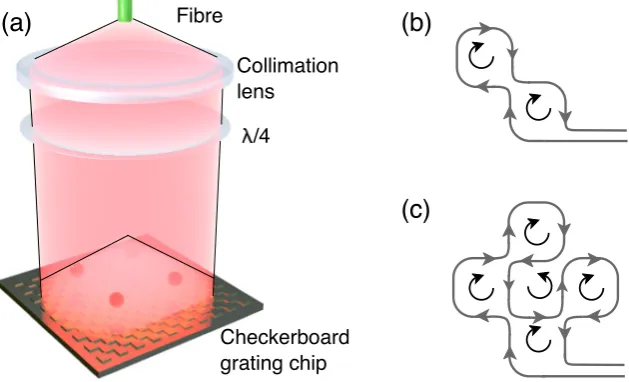
Figure 5. (a) Schematic of checkerboard grating. Linearly polarised light diverges from the optical fibre, is
[image:4.595.154.363.45.178.2] [image:4.595.157.472.233.424.2]and 2D arrays28, however an array of neutral atoms is favourable due to their weaker interaction with the
envi-ronment29. A common method for generating a neutral atom array with a small number/one atom per site is in
an optical lattice, where individual microscopic site addressing and measurement is restricted to the regime of the quantum gas microscopes30, 31 and optical dipole traps32.
Large macroscopic arrays of neutral atoms have been achieved in the form of a magnetic lattice loaded from cold atoms, capable of capturing up to 2000 atoms in 500 sites29. Macroscopic scaled neutral atom arrays with
larger N have also been demonstrated in the form of a 2 × 2 array of MOTs33 where the scalability is limited by the
optical set-up. Here we introduce the micro-fabricated grating chip as a simple and robust source for generating 1D and 2D arrays of neutral atoms with a single incident laser and patterned coil geometry.
For this study, the holographic checkerboard grating chip, discussed in previous literature11, 13, was
imple-mented into the set-up. The benefit of the checkerboard grating is the lack of a central symmetry point that exists in the linear gratings. Instead, the overlap volume extends to fill the surface area of the chip11, making it accessible
to lay a patterned coil beneath the surface of the grating to form a number of MOTs dependent upon the coil geometry, as can be seen in Fig. 5(a).
To create the appropriate inhomogeneous magnetic potential for multiple MOTs, we used the coil design illustrated in Fig. 5 with an additional external bias field orientated perpendicular to the plane of the coils. The wire geometries used in Fig. 5(b,c) were selected for a 1D and 2D array respectively. Here the grey lines represent the wire formation, with black curves used to emphasize the direction of current flow. For (b), the selected wire
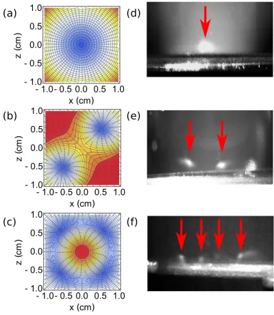
Figure 6. (a–c) Standard anti-Helmholtz simulation, two magnetic minima simulation for a 1D array and four
[image:5.595.150.551.44.505.2]π α µ π α α − = + − − −
B r z
r r mE K
B r z I
r m
r rK
m r m
m E
( , )
2 4 2 2 ,
( , )
2 4
(2 )
2 2 , (4)
r
z 0
where r and z are the radial and axial co-ordinates, α is the coil radius, = α α
+ +
m z2 4( r r)2 and the functions E and K refer to the corresponding elliptic integrals E m( )=
∫
0π/2(1−msin )2 1/2θ dθ and =∫
π θθ −
K m( ) 0/2(1 mdsin )2 1/2. These equations were used to simulate the magnetic potential for a single MOT, as well as for the geometries of Fig. 5(b,c), as shown in Fig. 6 (a–c) respectively. The required wire geometries were formed in a 3D-printed mount and placed immediately below the grating. The geometry patterned coil would then be run with a small bias coil in conjunction with an upper coil to create the appropriate magnetic field required. The experimental observations of this can be seen in Fig. 6(d) for a single MOT, (e) for 2 MOTs in a 1D array and (f) for 4 MOTs in a 2D array. The images seen in (d) and (e) were taken with the grating mounted outside of the vacuum, using ~25 mW/cm2 to start with 2 × 10⁶ atoms in (d) which was then split into 2 MOTs with 5 × 10⁵ atoms each. For image (f) the grating and patterned coil were mounted inside the vacuum due to the magnetic minima forming close to the grating surface, forming 4 MOTs using ~2 mW/cm2, with an estimated <105 atoms in each.
This demonstration proves the potential of the GMOT in future quantum sensing devices requiring an atomic array. Most notably, such a device would prove beneficial to the realisation of a compact gradiometer, where an array of identical MOTs can be used for cancellation of common mode noise.
Conclusions
In summary, we have demonstrated ultra-cold temperatures in a grating magneto-optical trap, as a platform for compact quantum sensing. This demonstration looked at the critical parameters for achieving low temperature systems, such as the magnetic environment.
We conclude that pressure measurements determined by the loss rate from a magnetic trap illustrate that these low temperatures can be achieved in a compact vacuum apparatus, even with pressure on the order of 10−7 mbar. The introduction of Larmor precessions in a cold 87Rb atomic sample for the nulling of stray static and gradient magnetic fields provides an accuracy of static field levels below 1 μT and an order of magnitude improvement of gradients.
Finally, the demonstration of multiple magneto-optical trap locations from a single incident laser beam cou-pled to a 2-dimensional diffractive optic opens the door to a compact cold-atom gradiometer. This can be taken further to introduce an array of cold atomic ensembles, with the array number and geometry solely determined by the trapping coil design.
The dataset for this paper is available at doi:10.15129/79a69c9c-3f61-428f-b52e-366017fafa89.
References
1. Takamoto, M., Hong, F. L., Higashi, R. & Katori, H. An optical lattice clock. Nature 435, 321–324 (2005). 2. Ludlow, A. D. & Ye, J. Progress on the optical lattice clock. Comptes Rendus Physique 16, 499–505 (2015).
3. Esnault, F. X., Donley, E. A., Kitching, J. & Ivanov, E. N. Status of a compact cold-atom CPT frequency standard. Proc. 2011 Joint Mtg. IEEE Intl. Freq. Cont. Symp. and EFTF conf. 612–614 (2012).
4. Bodart, Q. et al. A cold atom pyramidal gravimeter with a single laser beam. Appl. Phys. Lett. 96, 134101 (2010).
5. Lee, J., Grover, J. A., Orozco, L. A. & Rolston, S. L. Sub-Doppler cooling of neutral atoms in a grating magneto-optical trap. J. Opt. Soc. Am. B 30, 2869–2874 (2013).
6. Zhang, H., Li, T. & Yin, Y. Microtrap on a concave grating reflector for atom trapping. Chinese Phys. B 25, 087802 (2016). 7. Pollock, S., Cotter, J. P., Laliotis, A. & Hinds, E. A. Integrated magneto-optical traps on a chip using silicon pyramid structures. Opt.
Express 17, 14109–14114 (2009).
8. Camposeo, A. et al. A cold cesium atomic beam produced out of a pyramidal funnel. Opt. Commun. 200, 231–239 (2001). 9. Arlt, J. J., Marago, O., Webster, S., Hopkins, S. & Foot, C. J. A pyramidal magneto-optical trap as a source of slow atoms. Optics
Commun. 157, 303–309 (1998).
10. Vangeleyn, M., Griffin, P. F., Riis, E. & Arnold, A. S. Single-laser, one beam, tetrahedral magneto-optical trap. Opt. Express 17, 13601–13608 (2009).
11. Nshii, C. C. et al. A surface-patterned chip as a strong source of ultracold atoms for quantum technologies. Nature Nanotech. 8, 321–324 (2013).
12. McGilligan, J. P., Griffin, P. F., Riis, E. & Arnold, A. S. Diffraction grating characterisation for cold-atom experiments. J. Opt. Soc. Am. B 33, 1271–1277 (2016).
25. Lett, P. D. et al. Optical molasses. J. Opt. Soc. Am. B 6, 2084–2107 (1989).
26. Cirac, J. I. & Zoller, P. A scalable quantum computer with ions in an array of microtraps. Nature 404, 579–581 (2000).
27. Rakholia, A. V., McGuinness, H. J. & Biedermann, G. W. Dual-axis high-data-rate atom interferometer via cold ensemble exchange.
Phys. Rev. Applied 2, 054012 (2014).
28. Stick, D. et al. Ion trap in a semiconductor chip. Nature Phys. 2, 36–39 (2006).
29. Whitlock, S., Gerritsma, R., Fernholz, T. & Spreeuw, R. J. C. Two-dimensional array of microtraps with atomic shift register on a chip. New J. Phys. 11, 023021 (2009).
30. Haller, E. et al. Single-atom imaging of fermions in a quantum-gas microscope. Nature Phys. 11, 738 (2015). 31. Sherson, J. F. et al. Single-spin addressing in an atomic Mott insulator. Nature 471, 319–324 (2010).
32. Bergamini, S. et al. Holographic generation of microtrap arrays for single atoms by use of a programmable phase modulator. J. Opt. Soc. Am. B 21, 1889–1894 (2004).
33. Grabowski, A. & Pfau, T. A lattice of magneto-optical and magnetic traps for cold atoms. Eur. Phys. J. D 22, 347–354 (2003). 34. Good, R. H. Elliptic integrals, the forgotten functions. Eur. J. Phys. 22, 119–126 (2000).
Acknowledgements
The authors would like to gratefully acknowledge discussion with C. Monroe. We acknowledge financial support from the EPSRC (EP/M013294/1), DSTL (DSTLX-100095636R), and ESA (4000110231/13/NL/PA).
Author Contributions
A.S.A., P.F.G. and E.R. conceived the experiment(s), J.P.M. conducted the experiment(s) and wrote the manuscript. All authors reviewed the results and manuscript.
Additional Information
Competing Interests: The authors declare that they have no competing interests.
Publisher's note: Springer Nature remains neutral with regard to jurisdictional claims in published maps and
institutional affiliations.
This work is licensed under a Creative Commons Attribution 4.0 International License. The images or other third party material in this article are included in the article’s Creative Commons license, unless indicated otherwise in the credit line; if the material is not included under the Creative Commons license, users will need to obtain permission from the license holder to reproduce the material. To view a copy of this license, visit http://creativecommons.org/licenses/by/4.0/