This is a repository copy of A new order parameter based method for characterizing radiation damage in amorphous materials.
White Rose Research Online URL for this paper: http://eprints.whiterose.ac.uk/122049/
Version: Accepted Version
Article:
Galanakis, N. and Travis, K.P. orcid.org/0000-0001-8557-2689 (2017) A new order parameter based method for characterizing radiation damage in amorphous materials. Langmuir. ISSN 0743-7463
https://doi.org/10.1021/acs.langmuir.7b02649
[email protected] https://eprints.whiterose.ac.uk/ Reuse
Items deposited in White Rose Research Online are protected by copyright, with all rights reserved unless indicated otherwise. They may be downloaded and/or printed for private study, or other acts as permitted by national copyright laws. The publisher or other rights holders may allow further reproduction and re-use of the full text version. This is indicated by the licence information on the White Rose Research Online record for the item.
Takedown
If you consider content in White Rose Research Online to be in breach of UK law, please notify us by
A New Order Parameter Based Method for
Characterizing Radiation Damage In
Amorphous Materials
Nikolaos Galanakis
∗and Karl P. Travis
Department of Materials Science & Engineering, University of Sheffield, Sir Robert
Hadfield Building, Sheffield, S1 3JD, UK
E-mail: [email protected]
Abstract
We present a new method of characterizing damage arising from α-recoil cascades
in amorphous materials including glasses. The approach taken is topological, yielding
information of atom connectivity and utilising complete sets of orthogonal functions
(spherical harmonics and Hermite functions) to compute order parameters.
The utility of our new approach is demonstrated by first applying it to models of
radiation damaged crystalline zircon, enabling validation against the standard defect
counting method (Wigner-Seitz). We then apply it to a simple model of a glass,
ob-tained by supercooling a Lennard-Jones liquid, for which defect counting methods are
inapplicable.
The method shows great promise for use in characterizing damage in more
compli-cated glasses, particularly those of interest in immobilisation of nuclear waste and when
used in conjunction with non-equilibrium computer simulation, could be a powerful tool
Introduction
In the UK and countries including France, Russia and India, high level nuclear waste (HLW)
is immobilized through a process known as vitrification. This process entails calcination
of the liquid waste, followed by melting the calcined wastes with a mixtures of glass frit
and various additives to control the final properties of the solid glass but also to control its
viscosity while molten. The molten mixture is then poured into stainless steel containers,
which are subsequently sealed and placed in dry storage, awaiting final disposal. Glass is the
preferred wasteform for HLW largely because of its chemical flexibility - it can incorporate
a large range of atomic species within the matrix. However, one of the disadvantages is a
low chemical durability. Self-irradiation from elements within the matrix, particularly alpha
decay cascades, can lead to loss of local structure, ultimately causing devitrification and
failure of the wasteform. Understanding the effects of alpha recoil cascades in amorphous
materials is a key step towards developing more durable and safer glass wasteforms.
Numerical modeling has emerged as a powerful tool to assist experimental studies of the
effects of radiation damage in wasteforms. Alpha cascades can be directly followed in real
time using non-equilibrium molecular dynamics in which an atom is selected as the primary
knock-on atom (PKA) and given an additional component of kinetic energy over and above
that due to thermal motions. The development of point defects, the propagation of
dam-age and any subsequent recovery can then be observed for a timescale typically up to 100
picoseconds at the atomic scale using classical forcefields and large system sizes. By
simu-lating damage in families of related materials, the numerical work can guide experimental
programmes by reducing the list of candidate materials to be explored. Importantly,
mecha-nistic information can be gleaned from computer experiments which is difficult or impossible
to obtain using experiment alone.
Assuming that the classical forcefields (ab initiomethods are presently restricted to small
numbers of atoms and thus low recoil energies) used to construct models of the wasteforms
radiation damage modeling involves a non-equilibrium process and the results are sensitive
to details such as heat removal (thermostatting), use of artificial boundary conditions (eg
pe-riodic boundary conditions) and the method used to characterize the damage. The method
of characterizing damage is perhaps the most significant outstanding problem in radiation
damage modeling. Traditional defect counting methods based on Wigner-Seitz cells are only
suitable for crystalline materials in which there is a clear reference structure from which to
compare against and thus enabling identification of point defects. Glasses, which are
amor-phous cannot be analysed using this method. However, even for crystalline materials, the
Wigner-Seitz method is still problematic since the unit cell may distort significantly during
a cascade - a fact not taken into account by the original method.1 In addition the atoms of a
glass are not in a state of thermodynamic equilibrium but instead undergo diffusive motion.
In that case the Wigner-Seitz method would record a large number of false-positive damaged
particles. For this reason, alternative methods based on topology have been developed and
used. These methods include the use of Steinhardt order parameters,2 ring statistics3–10 and
Maxwell constraint analysis.11–14
In all previous studies, Steinhardt order parameters (SOP) are used to obtain information
regarding the structure of crystalline materials. However, none of these studies use SOP to
provide information regarding the number of displaced particles. Moreover, with the
excep-tion of the work of Baranyai et al..15 SOPs have not been applied to amorphous materials
and particularly those used as nuclear wasteforms.
In this paper we report a new topological method of characterizing disorder arising from
radiation damage based on an extension of Steinhardt order parameters but also including
new order parameters based on Hermite functions. We validate our new method by
consid-ering radiation damaged crystalline zircon, in which the traditional defect counting method,
though not perfect, provides the means to check the new method. We next apply the method
to a simple model of a glass, namely the LJ glass, obtained by supercooling a LJ fluid. The
The paper is organized as follows. In the first section we describe the topological order
parameters used in our method. In the second section we describe the models used and
how they were prepared (crystalline zircon and LJ glass). In the third section we discuss
the results obtained by applying the new method to crystalline and amorphous solids while
in fourth section we discuss the usefulness of the method and indicate where it might be
applicable.
Topological measures of disorder
Steinhardt order parameters
Common topological methods involve bond order parameters and Steinhardt order
parame-ters. One of the uses of SOP was due to Baranyai et al..15These authors used SOP and more
particularly the Qℓ vs ℓ bar charts for the first coordination cell of each atom to explore the
differences in the structures of molten and glassy rubidium bromide. Lechner and Dellago16
used SOP to study the structure of simple crystalline Lennard-Jones systems and a Gaussian
core model, by investigating the distribution ofQ4 and Q6 as well as their average values for
all the atoms of the system. Unlike previous studies, Lechner and Dellago used both the first
and the second coordination cell for their calculations. Reinhardt et al.17 followed a similar
approach to investigate ice nucleation in water models. A more sophisticated approach was
followed by Archer et al.2 in order to study the structure of pyrochlores for nuclear waste
immobilization. These authors used two different cutoff distances for the calculation of the
SOP. One with a small cutoff distance of 3.2 Å, to obtain global information, and a secondary
cutoff distance of 12 Å to obtain information on local structures surrounding atoms.
Steinhardt Order Parameters18 provide information regarding the angular distribution of
is represented by the set of bond-orientational parameters defined by
⟨Qℓ,m(r)⟩= 1 Nb
Nb ∑
i=1
Qℓ,m(ri). (1)
where Nb is the number of bonds for the reference particle andQℓ,m =Ym
ℓ (r). Yℓm(θ, ϕ) are the complex spherical harmonic functions, defined by
Yℓm(θ, ϕ) = (−1)m √
2ℓ+ 1 4π
(ℓ−m)! (ℓ+m)!P
m
ℓ (cosθ)eimϕ, |m| ≤ℓ, (2)
for integers ℓ and m, with the latter restricted to values between −ℓ, +ℓ, while Pm
ℓ (x) are associated Legendre polynomials defined by
Pm ℓ (x) =
(−1)m 2ℓℓ! (1−x
2)m/2 dℓ+m dxℓ+m(x
2−1)ℓ, m≥0, (3)
Pℓm(x) = (−1)m(ℓ+m)! (ℓ−m)!P
|m|
ℓ (x), m <0. (4)
In the above equations, θ ∈ [0, π] and ϕ ∈ [0,2π] are the polar angle and azimuth of the
spherical coordinate system. In the foregoing, the word "bond" is interpreted to mean the
radius vector connecting a reference atom to one of its neighboring atoms lying within a
sphere of specific radius, centered to the reference atom. Spherical harmonics for a given
value of ℓ are members of the SO(3) rotational group that represents all the rotations in
the 3D Euclidian space under the operation of composition. They are coordinate system
dependent. To avoid this inconvenience the rotationally invariant term:
Qℓ = [
4π 2ℓ+ 1
ℓ ∑
m=−ℓ
|⟨Qℓ,m(r)⟩|2 ]1/2
, (5)
are also calculated. Since a radiation damage event will change the relative positions of the
Hermite order parameters
The atoms of a crystalline solid occupy positions in the minima of the potential energy
surface. Except at 0 K, these atoms vibrate about these equilibrium positions. The
instan-taneous bond vector connecting a reference atom to a given neighbor will change according to
the vibrational motion of these atoms. Unless this motion is taken into account, misleading
information could be obtained from SOP measures of radiation-induced disorder. A solution
to this potential problem is as follows. Consider a reference particlei and the motion of an
atomj at time t, described by the position vectorrij(t), relative to its (0 K) position vector
rij,eq(0) at the reference site. We can resolve this motion into a component parallel to this position vector:
rij∥(t) = rij(t)·rij,eq(0), (6)
and a component perpendicular to it, defined by the equations:
r⊥ij(t)·rij,eq(0) = 0, (7)
r⊥ij(t)·[rij(t)×rij,eq(0)] = 0, (8)
|r⊥ij(t)|= |
rij(t)×rij,eq(0)| rij(0)
. (9)
The first equation ensures that the component is perpendicular to vectorri,eq(0), the second
that it lies at the same plane as vectors ri,eq(0) and ri(t) and the third that it has the
appropriate length. Steinhardt order parameters are independent of the polar distancer and
they actually ignore the movement of atom j which is parallel to the direction of rij,eq(0).
SOP are only able to measure the rotational motion defined by vector r⊥ij(t). However,
the motion captured by the parallel component is vibrational in nature and is more suitably
represented by Hermite functions which emerge from the solution of the quantum mechanical
position and they are able to record any alteration in the distance between two particles.
This applies to the radiation damage situations where it is expected that Hermite functions
will give information regarding the displacement of particles from their initial positions.
The Hermite functions are defined by
ψn(x) = (2nn!√π)1/2Hn(x)e−x2/2, n = 0, 1, 2, . . . (10)
where Hn(x)are the Hermite polynomials
Hn(x) = (−1)nex2 d n
dxne
−x2
, n= 0,1, 2, . . . (11)
To enhance the effect of n and to be able the distinguish the different parameters, we define
a set of modified Hermite functions, ψnme (x) = (x):
e
ψnm(x) = (2nn!√π)1/2Hn(x)eanmx2/2, n= 0, 1, 2, . . . (12)
in which anm = n/nm with nm the largest value of n used in the calculations. These new
functions retain the important orthogonality property, but are no longer normalized (this
has no bearing on any of the results obtained).
Using the Hermite functions defined in eq. (12), we can construct a new order parameter
which we shall henceforth refer to as a Hermite Order Parameter - HOP. By analogy with
the SOPs, we define an average HOP by
⟨ψne (r)⟩= 1 Nb
[ N b ∑
i=1
|ψnme (ri)|2
]1/2
, (13)
where the "bond" distance denoted byrin the above formula is obtained from the magnitude
Model and force fields
Crystalline zircon
Zirconium silicate, commonly known as zircon, is a mineral with chemical formula ZrSiO4
that crystallizes with the I41/amd space group. A significant amount of research has been
devoted to molecular dynamics simulations of radiation damage in zircon (see for example
Trachenko et al.19–21and Devanathan et al.22) which makes the modelling of radiation
dam-aged zircon crystal quite straightforward. Apart from the study of radiation damage effects,
these studies contributed to the establishment of reliable interatomic potentials for the zircon
crystal.
A model for crystalline zircon consisting of a supercell of 5184 atoms was created
us-ing the DLPOLY 4 software package23 (unit cell of 24 atoms). There are several different
forcefields suitable for radiation damage modelling in zircon each with their own merits and
disadvantages. In this work we have used one developed by Trachenko et al.20 due to its
ability to closely reproduce the structural properties of zircon, while simultaneously giving
a reasonable estimate for the elastic constants.
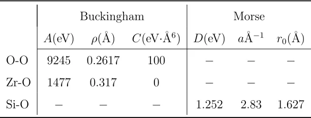
The zircon forcefield consists of a Buckingham pairwise additive potential energy, ϕ(r),
describing interactions between pairs of Zr-O and O-O atoms:
ϕBuck(r) =Ae−r/ρ−
C
r6. (14)
with r = |rij|; rij = ri −rj, and parameters A, ρ and C are given in Table 1. For Si-O
interactions, a Morse potential wa instead used:
ϕMorse=D
[
e−2a(r−r0)
−2e−a(r−r0)]
. (15)
with values for the parameters D, a, r0 also given in Table 1.
inter-actions resulting from the partial charges assigned to the atomic species. The charges used
for Zr, Si and O ions are +3.428, +1.356, and −1.196 respectively. The Coulombic
con-tribution was evaluated using the Ewald summation method. In our simulations, we used
an automatic parameter optimization for k-space provided by DLPOLY 4, and a real space
cutoff of 25 Å. Once an initial superstructure had been created, it was relaxed using this
forcefield through use of the energy minimization routine provided by the GULP software
package.24
The energy-minimized structure previously described was equilibrated for a period of
10 ps at 300 K using NVT molecular dynamics. The temperature was controlled using a
Langevin thermostat.
To create a damage cascade, a silicon particle (the primary knock-on atom, pka) is chosen
near the centre of the supercell and given an additional quantity of kinetic energy equal to
4 keV over and above its thermal component. This kinetic energy defines the magnitude of
the pka; its direction was selected such that its motion was directed along the [111]
crystal-lographic direction. The high kinetic energy of the pka can create an extended and easily
quantified damage cascade. However, the simultaneous use of periodic boundary conditions
may allow energetic particles to travel through the periodic boundaries of the simulation
box and either self-interact or create additional damage in regions of the simulation box that
should not be affected by the radiation event. To prevent the energetic particles from
[image:10.612.153.459.599.715.2]trav-eling through the boundaries and re-entering the system during the non-equilibrium phase
Table 1: Parameters of the Buckingham and Morse potentials used for the zircon crystal model.
Buckingham Morse A(eV) ρ(Å) C(eV·Å6) D(eV) aÅ−1 r
of the simulation, a Langevin boundary layer thermostat was applied at 300 K. Because of
the small system size employed, the width of this boundary layer was taken to be 2 Å
-the lowest possible value allowed by -the DLPOLY 4 code. By examining -the trajectories of
the particles during the simulation, this boundary layer was proved sufficient to remove the
excess of kinetic energy of the energetic particles and prevent them from traveling through
the boundaries of the simulation box. A variable time step algorithm was applied that
al-lowed the atoms of the system to travel a distance between 0.01 Å and 0.05 Å per time step,
for 50,000 timesteps. The initial and the final timestep of the simulations was 0.01 fs and
0.1 fs respectively. The large kinetic energies involved in high energy cascades can lead to
an increased possibility of smaller ionic separations that probe the divergent region of the
Buckingham potential, giving rise to large (attractive) forces and unphysical clustering of
similarly charged ion species. To avoid this, we have truncated the Buckingham potential
for O-O interactions, replacing it at short distance with the ZBL potential,25joining the two
smoothly with a cubic spline. The combined potential energy (not including the electrostatic
contribution) is then defined piecewise by
ϕO-O(r) =
ϕZBL(r), r≤rZBL
ϕspline(r), rZBL< r < rBuck
ϕBuck(r), r ≥rBuck
(16)
where rZBL= 0.4 Å and rBuck = 1.0 Å.
Lennard-Jones glass
A LJ glass was constructed by supercooling a well-equilibrated LJ fluid following the method
fcc lattice of 4000 atoms which are allowed to interact via the LJ pair potential
ϕLJ(r) = 4ϵ
[(σ r
)12
−(σr)6
]
, (17)
whereϵis the depth of the potential well andσ is the distance at which the potential is zero.
The fcc lattice was constructed with a reduced number density, ρσ3 = 0.95. Using σ = 3.4
Å, this corresponds to a simulation cell length of 54.983 Å. The fcc structure then underwent
a period of equilibration using DLPOLY 4 with a Nose-Hoover thermostat with set point
temperature T = 216 K for 50,000 timesteps. The resulting fluid was then quenched using
the same dynamics but now at T = 12.96K to yield an amorphous solid LJ glass.
For the creation of the radiation damage cascade, an NVT Langevin thermostat was
used with a boundary layer of 2 Å. The pka was given a kinetic energy of 0.2 eV and with a
velocity direction chosen so that it traveled along the [111] crystallographic direction. The
variable step algorithm was the same as for the simulation of the damage cascade in the
zircon crystal and the simulation was run for 150,000 time steps.
Algorithmic details for defect analysis
The output of each simulation was recordered every 100 timesteps giving a total of 501
con-figurations (frames) to analyse, with one frame representing the initial undamaged structure,
and the remaining 500 being the damaged structure. Each of these frames was analysed with
both the traditional defect counting method and the two proposed topological order
param-eter methods. In the following sections we outline the procedure by which each of these tools
was used.
Defect counting
Defect counting was performed using the in-built routine provided by DLPOLY 4.23 The
configuration (frame 1). In general, a particle may leave its original atomic site creating a
vacancy. If the final position of this particle lies within a fixed distance of an atomic site
occupied by another atom, an interstitial defect results. The site-interstitial cutoff distance
was selected equal to 1.8 Å, corresponding to half of the mean Ar-Ar bond distance. Antisite
defects are not distinguished by the DLPOLY 4 defect counting routine.
A particle is considered to be a member of the set of "damaged" particles i.e a defect, if
the displacement from its original undamaged crystalline position exceeds 50% of the value
of the shortest bond-length of the system. The shortest "bond length" can be obtained from
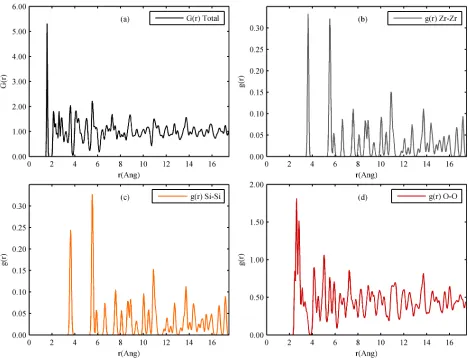
[image:13.612.74.543.295.653.2]the radial distribution function. The partial radial distribution function for a pair of atomic
sites of speciesα and β is defined as:
gαβ(r) = V nαnβ
nα ∑
i nβ ∑
j̸=i
⟨δ(r−rij)⟩, (18)
whereV is the system volume,nα and nβ are the respective number of atoms of type α and
β. The total radial distribution function, is obtained from:
G(r) = ∑ α
∑
β
gαβ(r). (19)
Radial distribution functions for pristine (undamaged) zircon are shown in Figure 1. The
first maximum inG(r)(Figure 1.a) occurs at a distance of 1.55 Å and so we set the "damage
distance", rd = 0.75 Å, which is a little less than half this value. For the LJ system, the
position of the first maximum in G(r) is at 3.78 Å. Initially we tried a value of rd= 1.85 Å
for this system of and so the damage distance is selected equal to 1.85 Å. However, we had
to modify this distance to the lower value of 1.75 Å after trial runs led to the observation
of multiple occupancy of atomic sites (two or more atoms were simultaneously found in the
same atomic site).
Order parameters
To properly characterize the damage from a recoil cascade event, we have calculated
species-specific Steinhardt and Hermite order parameters. The method for doing this is as follows:
The zircon structure was separated into three substructures, each containing only atoms
of the same type. For each of these substructures, a list of the nearest neighbors for every
reference particle was constructed, by using the position of the first minimum of the respective
partial g(r) as a cutoff distance. Two particles A and B are considered to be bonded if the
distance rAB between them is shorter that the first minimum of both the partial radial
calculated for 0 < ℓ ≤ 10, while HOP were obtained for 0 < n ≤ 16, for each of the 500
frames. The algorithm for computing these order parameters consisted of the following steps:
(1) An atom is chosen in one of the configurations - the reference atom; (2) distances and
angles are obtained for each of the near neighbors of the reference atom and used to compute
the SOPs and HOPs. (3) The procedure is repeated until every atom has been selected as
the reference atom.
For the initial undamaged structure, the average value of SOP and HOP is calculated.
Then for each damaged frame, the number of particles with a SOP/HOP value above the
average, ng(t), is calculated and compared with the respective number ng(0) in the initial
structure. Finally, the number of particles: nh(t), with SOP/HOP increased values when
compared with the respective values in the reference frame is calculated.
Extra care is needed when handling periodic boundaries. Since the analysis was
per-formed using the output file of the simulation, to avoid overcounting the number of damaged
particles, atoms that travel through the boundaries of the simulation box are identified
dur-ing the analysis and their positions are fixed to be the same as in the initial undamaged
structure.
During the analysis, when identifying nearest neighbors, the minimum image convention
method was not applied. Instead, the initial undamaged structure was replicated 3 times
in each spatial dimension (27 replicas in total). For the analysis of the damaged structure,
only the positions of the atoms that lie within the original cell are updated. For the creation
of the neighbor list, it is necessary to calculate the distances between all the particles of the
substructure. To decrease the calculation time, the replicated supercell was truncated to
include only replicated atoms that lie within a distance less than the first minimum of the
partial RDF from the surface atoms.
Additionally, to avoid identifying as damaged a particle that simply undergoes thermal
vibration, a special condition is applied in the calculation of SOP/HOP. For each reference
The difference dij(tn) = |rij(tn)−rij(0)| of the distance rij between each damaged frame
(labeled as timetn) and the reference frame (t = 0) is calculated. The process is depicted in
Figure 2. To characterize a particle as a possibly damaged particle, we require at least one
of the distance differences, dij, to be greater than the distancerd. If none of these satisfy the
condition, SOP/HOP values for the specific reference particle are set to the values calculated
for the same particle in the initial undamaged frame.
This method does not automatically characterize a particle as damaged. If dij(tn)> rd,
then when particle j is used as reference particle it will also be dji(tn)> rd. This way, the
SOP/HOP values of both particles will be affected, classifying both particles damaged when
only one of the pair may be so. To avoid erroneous estimation of the number of damaged
particles, a correlation between the actual number of damaged particles and the numbers
ng(t) and nh(t) is performed. In the initial undamaged substructure for each species, a number of particles, equal to 10% of the total number of particles in the substructure, are
deliberately displaced from their initial positions by a distanceR > rdto create an artificially
damaged structure. The quantities: ng(t) and nh(t) are calculated for this case and are
compared with the number of deliberately damaged particles. To increase the accuracy of
the correlation, this step is repeated 100 times and the number of damaged particles is
compared with the average ng(t) and nh(t)values.
For amorphous materials, because of the diffusion, it is not safe to create deliberately
damaged structures by using only the initial undamaged one. Instead, we equilibrate the
reference structure for 50k timesteps using NVT dynamics to create 500 deliberately damaged
structures, every 100 steps, by using the output file of the simulation. We used each of these
frames to find the correlation between the actual number of damaged particles and the
numbers ng(t)and nh(t).
Not allQℓ and⟨ψne (r)⟩give a satisfactory estimation of the number of damaged particles,
requiring a sifting process, conducted as follows: First, the average values of SOP/HOP
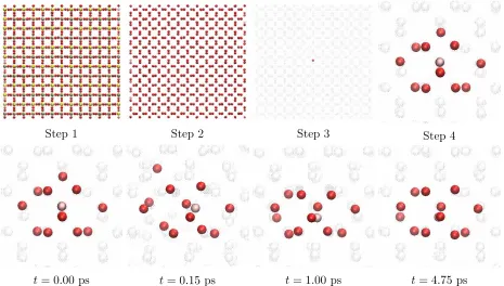
Step 1 Step 2 Step 3 Step 4
[image:17.612.75.540.71.335.2]t= 0.00 ps t= 0.15 ps t= 1.00 ps t= 4.75 ps
Figure 2: The process of the SOP/HPP calculation. From the initial undamaged structure (step 1), a substructure is created by selecting the atoms of a single species (here the oxygen atoms, step 2). A reference particle is selected (step 3) and its nearest neighbours are identified (step 4). This "local" structure is observed during the total time of the simulation and the SOP/HPP are calculated for each frame.
which have the expected qualitative behaviour are selected. For these values, we calculate
correlation coefficients between the number of deliberately damaged particles and the number
of particlesnh(t). For example, for the zirconium atoms it was found that for 86 deliberately
displaced atoms, nh(t)receives an average value of 35.13. For the actual damaged structure,
the number of damaged particles is obtained using the formula
nd(t) = 86
35.13nh(t). (20)
Some of the selected values ofℓ, ncan give rise to negative values for the number of damaged
particles becauseng(t)< ng(0). These members of the set were subsequently discarded. The
number of damaged particles estimated for the different selectedℓ, nvalues are then averaged
Results
Radiation damage in crystalline zircon
The damaged zircon crystal was analysed using both defect counting and the proposed
topological methods in order to demonstrate the accuracy of the latter.
Defect counting
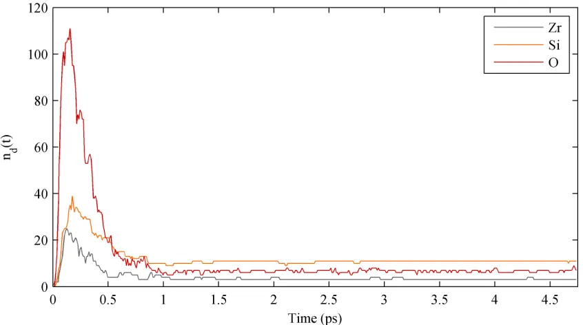
Figure 3 shows the actual number of damaged particles for the three different species (Zr,
Si and O) for zircon as determined using the inbuilt defect counting algorithm in DLPOLY
4 (Wigner-Seitz method). In each case, the number of damaged atoms rises to a maximum
in a time∼ 0.25 ps, before falling again and then reaching a plateu at∼ 1 ps. The greatest
number of damaged particles are O species, with a peak damage value of 111 atoms. The
[image:18.612.98.521.395.631.2]respective values for the silicon and zirconium species are 39 and 25.
Steinhardt order parameters
The curves showing the number of damaged particles as calculated using the defect
count-ing method, follow the characteristic damage-like pattern shown in figure 3. Regardless of
whether the material is crystalline or not, it is expected that the number of damaged
parti-cles will follow a similar pattern. The only differences are expected at the rate at which the
number of damaged particles are increasing at the beginning of the simulation and also at
the recovery stage which will define the number of particles that will form the plateau. Since
our effort is to correlate the SOP values with the number of damaged particles, we assume
that the evolution of SOP must follow a similar pattern.
For the zircon system, the time evolution of the majority of SOP follows a rather arbitrary
pattern. However, by comparing with the time evolution of the number of defects, it is
found that for some values of ℓ the evolution of the SOP exhibits a "desired behaviour", by
reaching a maximum value at the time of maximum damage and forming a plateau starting
at 0.5 < t < 1 ps. For the zirconium and silicon atoms, Q1, Q6 and Q9 demonstrated a
damage-like evolution, as shown in figure 4, while for the oxygen atoms it was Q9 and Q10.
It can be argued that the evolution of these SOP values is directly related to the number of
defects of the system. The calculated number of damaged particles using SOP method for
each of the threeℓvalues were averaged and the result gave good agreement with the number
of defects calculated by the Wigner-Seitz method for both the zirconium and silicon atoms
(Figures 5 and 6), especially in the recovered crystal. For the oxygen atoms however (Figure
7) there is a strong disagreement in the recovery region. However this can be explained by the
fact DLPOLY defect counting routine cannot identify antisites, which are quite numerous.
A simple way to estimate the number of total defects for each species, is to find for
each of the damaged frames the number of atoms that are displaced by r > rd. The total
number of oxygen defects is plotted in Figure 7. As can be seen, the total number of oxygen
defects in the equilibrium region is still lower in comparison with the number estimated with
Figure 4: The time evolution of Q1,Q6 and Q9 for the zirconium species. The plot demon-strates the values ofQl(t)−Ql(0) normalized to give unit maxima. These three was the only SOP that presented a damaged-like behavior.
higher order SOP in order to have the ability to average the number of estimated damage
particles for even more ℓ values and get a better statistical distribution, but this will have
a computational cost. To compute SOP up to ℓ = 16, the computational time becomes 2.4
times higher and 5.2 times for values up to ℓ = 24. However, since in amorphous materials
there are no antisites, we expect that the SOP method will give an excellent account of
the number of damage particles, as in the case of zirconium and silicon atoms of the zircon
crystal.
Hermite order parameters
For the zircon atoms⟨ψe9(r)⟩,⟨ψe10(r)⟩,⟨ψe11(r)⟩,⟨ψe12(r)⟩,⟨ψe14(r)⟩and⟨ψe15(r)⟩demonstrated
a damage-like evolution with time while for silicon atoms ⟨ψe10(r)⟩, ⟨ψe11(r)⟩, ⟨ψe14(r)⟩ and
⟨ψe15(r)⟩ were used. For the oxygen atoms, only ⟨ψe2(r)⟩ demonstrated the desired behavior. The results obtained with HOP method for zircon and silicon (Figures 5 and 6) show very
can be regarded as a self-validation of the two proposed methods in the case where there
are no antisites in the system. There seems to be a small overestimation of the maximum
damage for the silicon and oxygen atoms. This problem can be solved by modifying the
criteria under which the method identifies a damaged particle, in order to take into account
not only the distance between the nearest neighbours, but also the local geometry.
For both SOP and HOP methods, the results show a clear correlation between the number
ng(t) and the actual number of damaged particles nd(t) as calculated using the traditional defect counting method provided by the DLPOLY 4 in-built defect calculation routine. The
fact that the results obtained with SOP and HOP methods converge is very important in
cases were the defect counting method is not applicable or erroneous, as for amorphous
materials. We can use both methods to calculate the number of damaged particlesnd(t)and
[image:21.612.95.520.368.606.2]estimate the accuracy of the results by checking if they converge to the same values.
Figure 6: Comparison between the number of defects of the silicon atoms calculated using Wigner-Seitz method and the number of zirconium damaged particles calculated using SOP and HOP methods.
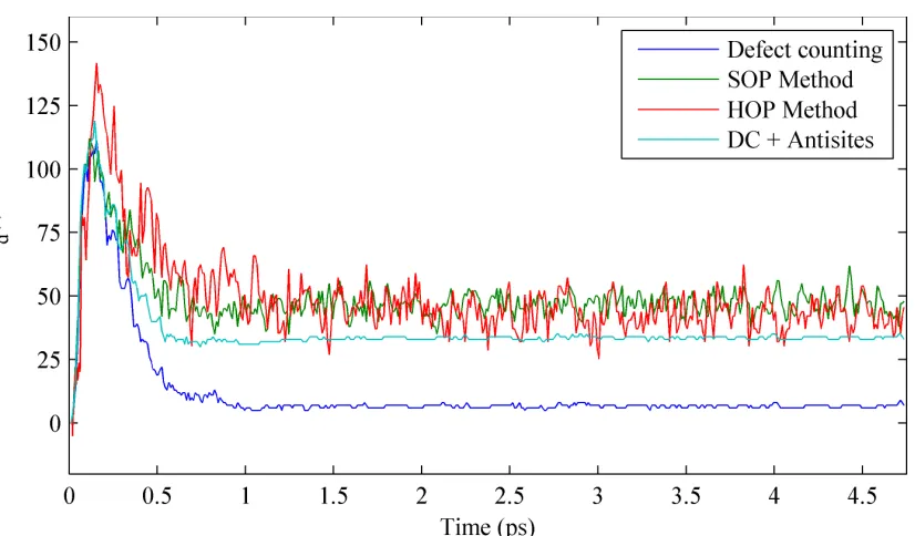
[image:22.612.108.521.407.649.2]Radiation damage in Lennard Jones glass
The traditional defect counting method shows a steadily increasing number of damaged
particles in the glass for the radiation damaged structure and for the first 1.5 ps of the
simulation and then a recovery is observed (Figure 8). The final number of damaged particles
is estimated around 800. However, since we have an amorphous material we expect the defect
counting method to overestimate the damage at the end of the simulation. In amorphous
materials, there are no point defects - instead we have bond defects. There is the possibility
that because of the damage and the diffusion observed in amorphous materials, a local
cluster of particles to move all together or rotate around an axis or both, making all the
particles to be displaced from their initial positions by more than rd, but without breaking
any bonds. While there is no damage in this cluster, the Wigner-Seitz method will identify
all the particles of the cluster as false-positive damaged particles.
The SOP/HOP methods on the other hand, do not use the initial structure to identify
the number of damaged particles - they only use the local environment of each particle.
The damage is estimated based on the alterations of this local structure. Additionally, the
fact that a correlation map is generated from an equivalent equilibrium structure makes this
method immune to the effect of diffusion. Using Q5,Q8 and ⟨ψe13(r)⟩ for the SOP and HOP
methods respectively and as argued above, the SOP/HOP method estimates a significantly
lower number of damaged particles at the end of the simulation (Figure 8). However, the SOP
method seems to overestimate the damage at the initial stages of the simulation. This fact
can also be explained based on how a damaged particle is defined in amorphous materials.
Although there is not a perfect correlation between the two proposed methods, the results
Figure 8: The evolution of radiation damage in a simple Lennard-Jones system, calculated with the traditional Wigner-Seitz method and with the two proposed topological methods.
Discussion and conclusions
We have developed two different topological methods to characterize the radiation damage
effects in amorphous materials, based on Steinhardt order parameters and Hermite
polyno-mial parameters. These method were tested on a zircon system to estimate the number of
damaged particles for each species separately. The results obtained with both methods are
consistent with the simple defect counting technique based on the Wigner-Seitz method, in
case there are no antisites in the system. For systems with antisite defects, the SOP method
seems to overestimate the damage at the recovery stage. When applied to a simple
Lennard-Jones system, SOP and HPP methods estimate a higher number of damaged particles for the
initial stages of the damage simulation and a lower number in the recovery region, which can
be explained using reasonable arguments based on the nature of the damage in amorphous
materials.
Although these new topological methods could be improved in order to be consistent for
all systems - including structures with antisite defects - they show great potential towards
develop-ments of the method will be able to give accurate information regarding the extent and the
mechanism of the damage in both global and local level.
References
(1) Hobbs, L. W. In Engineering of Crystalline Materials Properties: State of the Art in
Modeling, Design and Applications; Novoa, J. J., Braga, D., Addadi, L., Eds.; Springer
Netherlands: Dordrecht, 2008; Chapter Topological Approaches to the Structure of
Crystalline and Amorphous Atom Assemblies, pp 193–230.
(2) Archer, A.; Foxhall, H. R.; Allan, N. L.; Gunn, D. S.; Hardind, J. H.; Todorov, I. T.;
Travis, K. P.; Purton, J. A. Journal of Physics: Condensed Matter 2014, 26, 485011.
(3) Guttman, L. Journal of non-crystalline solids 1990, 116, 145–147.
(4) Hobbs, L. W.; Sreeram, A.; Jesurum, C. E.; Berger, B.Nuclear Instruments and
Meth-ods in Physics Research B: Beam Interaction with Materials and Atoms 1996, 116.
(5) Hobbs, L. W.; Jesurum, C. E.; Pulim, V.; Berger, B. Philos. Mag. A 1998, 78.
(6) Yuan, X.; Hobbs, L. W.Nuclear Instruments and Methods in Physics Research Section
B: Beam Interactions with Materials and Atoms 2002,191, 74 – 82.
(7) Dewan, L.; Hobbs, L. W.; Delaye, J.-M. Modeling Radiation-Induced Alteration of the
Network Structure of Alkali Borosilicate High-level Waste Glass. MRS Online
Proceed-ings Library Archive. 2011; p 1298.
(8) Dewan, L.; Hobbs, L. W.; Delaye, J.-M. Journal of Non-Crystalline Solids 2012, 358,
3427 – 3432, Glasses for Energy.
(9) Krishnan, N. M. A.; Wang, B.; Yu, Y.; Le Pape, Y.; Sant, G.; Bauchy, M. Phys. Rev.
(10) Krishnan, N. M. A.; Wang, B.; Pape, Y. L.; Sant, G.; Bauchy, M. The Journal of
Chemical Physics 2017, 146, 204502.
(11) Hobbs, L. W. Journal of Non-Crystalline Solids 1995, 182, 27 – 39.
(12) Thorpe, M.; Jacobs, D.; Chubynsky, N.; Rader, A. InRigidity Theory and Applications;
Thorpe, M. F., Duxbury, P. M., Eds.; Springer US: Boston, MA, 2002; pp 239–277.
(13) Foxhall, H.; Travis, K.; Hobbs, L.; Rich, S.; Owens, S. Philosophical Magazine 2013,
93, 328–355.
(14) Wang, B.; Krishnan, N. M. A.; Yu, Y.; Wang, M.; Pape, Y. L.; Sant, G.; Bauchy, M.
Journal of Non-Crystalline Solids 2017,463, 25 – 30.
(15) Baranyai, A.; Puszta, L.; Ruff, I. Electrochemical Acta 1988, 33, 1229–1234.
(16) Lechner, W.; Dellago, C. The Journal of Chemical Physics 2008, 129, 1–5.
(17) Reinhardt, A.; Doye, J. P. K.; Noya, E. G.; Vega, C.Journal of Chemical Physics 2012,
137.
(18) Steinhardt, P. J.; Nelson, D. R.; Ronchetti, M. Phys. Rev. B 1983, 28, 784–805.
(19) Trachenko, K. O.; Dove, M. T.; Salje, E. K. H.Atomistic modeling of radiation damage
in zircon 2001, 1947–1959.
(20) Trachenko, K. O.; Dove, M. T.; Geisler, I.; Todorov, I. T.; Simth, B. Radiation damage
effects and percolation theory, 2004, 2623–2627.
(21) Trachenko, K. O.; Zarkadoulia, E.; Todorov, I. T.; Dove, M. T.; J., D. D.; Nordlund, K.
Nuclear Instruments and Methods in Physics Research 2012, B, 6–13.
(23) Todorov, I. T.; Smith, W.; Trachenko, K.; Dove, M. T.Journal of Materials Chemistry
2006, 16, 1911–1918.
(24) Gale, J. D.The Journal of Chemical Society, Faraday Transactions 1997,93, 629–637.
(25) Ziegler, J.; Biersack, J. P.; Littmark, U. In Treatise on Heavy-Ion Science: Volume 6:
Astrophysics, Chemistry, and Condensed Matter; Bromley, D. A., Ed.; Springer US: Boston, 1985; Vol. 1.
(26) Rahman, A.; Mandel, M. J.; McTague, J. P. Journal of Chemical Physics 1976, 64,