Proc IMechE Part H: J Engineering in Medicine 2016, Vol. 230(5) 429–439 ÓIMechE 2016 Reprints and permissions:
sagepub.co.uk/journalsPermissions.nav DOI: 10.1177/0954411916645134 pih.sagepub.com
The influence of simulator input
conditions on the wear of total knee
replacements: An experimental and
computational study
Claire L Brockett
1, Abdellatif Abdelgaied
1, Tony Haythornthwaite
1,
Catherine Hardaker
2, John Fisher
1and Louise M Jennings
1Abstract
Advancements in knee replacement design, material and sterilisation processes have provided improved clinical results. However, surface wear of the polyethylene leading to osteolysis is still considered the longer-term risk factor. Experimental wear simulation is an established method for evaluating the wear performance of total joint replacements. The aim of this study was to investigate the influence of simulation input conditions, specifically input kinematic magni-tudes, waveforms and directions of motion and position of the femoral centre of rotation, on the wear performance of a fixed-bearing total knee replacement through a combined experimental and computational approach. Studies were com-pleted using conventional and moderately cross-linked polyethylene to determine whether the influence of these simula-tion input condisimula-tions varied with material. The posisimula-tion of the femoral centre of rotasimula-tion and the input kinematics were shown to have a significant influence on the wear rates. Similar trends were shown for both the conventional and moder-ately cross-linked polyethylene materials, although lower wear rates were found for the modermoder-ately cross-linked poly-ethylene due to the higher level of cross-linking. The most important factor influencing the wear was the position of the relative contact point at the femoral component and tibial insert interface. This was dependent on the combination of input displacement magnitudes, waveforms, direction of motion and femoral centre of rotation. This study provides fur-ther evidence that in order to study variables such as design and material in total knee replacement, it is important to carefully control knee simulation conditions. This can be more effectively achieved through the use of displacement con-trol simulation.
Keywords
Joint simulators, knee prostheses, orthopaedic tribology, wear analysis/testing (biomechanics), contact kinematics
Date received: 18 June 2015; accepted: 8 March 2016
Introduction
Total knee replacement (TKR) is an increasingly com-mon surgical intervention for the treatment of arthritis and joint degeneration.1 Advancements in implant design, material and sterilisation processes have pro-vided improved clinical results.2,3 However, surface wear of the polyethylene leading to osteolysis is still considered the longer-term risk factor, particularly as life expectancy and activity levels increase.4
Experimental wear simulation is an established method for evaluating the wear performance of total joint replacements, with numerous publications over the last decade demonstrating the influence of design, material, size and sterilisation processes on the performance of TKRs.5–13 Experimental wear
simulation under loading and motion representative of in vivo conditions is used to predict clinical wear per-formance. However, it has been shown that variation in the experimental conditions, such as kinematic inputs and component alignment, will have an impact on the wear performance of a TKR.10,14–16
1Institute of Medical and Biological Engineering, School of Mechanical Engineering, University of Leeds, Leeds, UK
2DePuy Synthes Joint Reconstruction, Leeds, UK
Corresponding author:
Indeed, different research centres have adopted dif-ferent approaches to experimental wear simulation of TKRs, with different conditions all too common. The resulting contact point movement that these simula-tions produce will depend on the combination of many parameters including input displacement magnitudes, waveforms, direction of motion and femoral centre of rotation (CoR). All of these factors will influence the relative amounts of rolling and sliding and hence poly-ethylene wear rate. Furthermore, the surface wear of polyethylene has been shown to be dependent on con-tact pressure, cross-shear and surface areas of the poly-ethylene being worn.4
The knee simulation philosophy developed in the early 2000s at the University of Leeds10,17–19accounted for femoral rollback, with the femoral distal radius taken as the femoral CoR and an anterior shift of the tibia relative to femur during gait. Leeds/Prosim six-station knee simulators can be driven in either force or displacement control. The appropriate control regime is selected depending on the level of intrinsic constraint of the knee replacement. For example, displacement control being selected for prostheses that do not have intrinsic constraint within the design and rely on soft-tissue constraints in vivo. At a similar time, interna-tional standards for the wear simulation of TKRs were developed for force and displacement control regimes. The philosophy of the ISO standards appeared to be to maintain the tibia-femoral articulation within the cen-tre of the tibial component, and therefore, a femoral CoR representing an average centre of the femoral dis-tal and posterior radii was adopted.20The ISO CoR of the femoral component combined with the ISO displa-cement control kinematic inputs did not, however, replicate femoral rollback.20,21
When comparing the displacement control profiles of the ISO standard21with the Leeds profiles, both use similar waveforms and amplitudes for axial load (maxi-mum 2600 N) and flexion–extension angle (maxi(maxi-mum 58°). For the ISO standard, also described in the study by Johnson et al.,22 a maximum of 5-mm anterior– posterior (AP) displacement and internal–external (IE) rotation of between 22° and 6°was adopted.21 Leeds based their displacement control profiles for tibial rota-tion and AP translarota-tion on the data of Lafortune et al.,23who analysed healthy patients without replace-ment prostheses. This resulted in an IE tibial rotation profile of65°. For AP translation, two different kine-matic conditions were adopted to simulate two levels of activity, with a maximum AP displacement of either 5 mm (intermediate kinematics) or 10 mm (high kinematics).10
A further consideration is the direction of motion or polarities of the input kinematics. Interestingly, the maximum AP translation as defined in the displace-ment control standard at the time of this study21 was originally defined as posterior tibia translation/anterior femoral displacement. However, following a study by
Sutton et al.,24 who investigated how natural knees responded to the inputs from the load control standard, this was reversed in the latest edition of the standard25 (published in 2014). AP translation is now defined as anterior tibia translation/posterior femoral displace-ment. The Leeds approach has consistently used ante-rior tibial translation in order to replicate femoral rollback when combined with setting the femoral centre on the distal radius. The polarity of the IE rotation input profile has also been reversed in the 2014 edition of the standard.25
Computational modelling is an attractive approach to wear simulation in total joint replacements, allowing parametric studies at substantially reduced cost and time.26 Computational wear models have been devel-oped utilising either the simplified Archard’s wear law,27based on the sliding distance and load,26,28,29or the modified Archard’s wear law, based on the contact area and contact pressure.30More recently, a new wear formula based on the contact area and sliding distance has been developed and applied to computational wear models at the University of Leeds.4,6,31,32The computa-tional wear predictions from this new wear formula have been validated against experimental studies.5,31,32
The aim of this study was to investigate the influence of simulation input conditions on the wear performance of a fixed-bearing TKR through a combined experi-mental and computational approach. The simulation input conditions investigated were input kinematic magnitudes, waveforms and directions of motion and position of the femoral CoR. Furthermore, studies were completed using conventional and moderately cross-linked polyethylene to determine whether the influence of these simulation input conditions varied with the material.
Materials and methods
Materials
and (2) curved moderately cross-linked GUR1020 UHMWPE (5 MRad irradiated and remelted) inserts (Moderately cross-linked (XLKä) material). Several sets of tibial inserts were used in these studies, where each set comprised of n = 6, further details of which can be found in Tables 1 and 2.
Experimental methodology
The wear of the fixed-bearing knee replacements was investigated using a physiological six-station Leeds/ Prosim knee wear simulator (Simulation Solutions, Stockport, UK), in which TKRs were mounted anato-mically in each station. The central axis of each implant was offset from the aligned axes of applied load and tibial rotation from the centre of the joint by 7% of its width, in accordance with ISO 14243-1.20The CoR of the femoral components was taken as either the distal radius of the implant, as indicated by the device design, or according to the ISO standard, which was an average of the femoral distal and posterior radii (Figure 1).20
Each station had 6 degrees of freedom with four controlled axes of motion – axial load, femoral flexion, tibial IE rotation and tibial AP displacement. Abduction/adduction was allowed but not controlled. In order to eliminate station-specific differences, the samples were moved around the stations every million cycles (MC). Several test conditions were explored through the study (Table 3). The femoral axis loading (maximum 2600 N) and extension–flexion (0°–58°) input profiles were taken from the international stan-dards20,21 for all test conditions and are shown in Figure 2. The IE tibial rotation was displacement con-trolled and set at65°based on the natural kinematics of the knee as described by Lafortune et al.23 and as shown in Figure 3. AP translation was displacement controlled for all studies, as this design of fixed-bearing knee replacement had minimal constraint and thus relies on soft tissue in vivo. The displacement test con-ditions used were ‘intermediate kinematics’ with an AP displacement of maximum 5 mm and ‘high kinematics’ with an AP displacement of maximum 10 mm. Table 3. Experimental test conditions.
CoR Distal radius ISO
Kinematic condition High kinematics Intermediate
kinematics
Modified high kinematics
Modified intermediate kinematics
ISO
Maximum AP displacement and polarity
210-mm anterior tibial shift
25-mm anterior tibial shift
10-mm posterior tibial shift
5-mm posterior tibial shift
5-mm posterior tibial shift
Internal–external rotation
65° 65° 65° 65° 22°to + 5.5°
CoR: centre of rotation; AP: anterior–posterior.
Table 1. Test order, duration and tibial insert set details for the GVFätibial inserts (n = 6 for each set).
CoR Distal radius ISO
Kinematic condition
Intermediate kinematics
High kinematics
Modified intermediate kinematics
Modified high kinematics
ISO
Testing order 1 2 5 3 4
Tibial insert set Set GVF 1a Set GVF 2 Set GVF 3 Set GVF 3 Set GVF 3
Test duration 3 MC 5 MC 3 MC 3 MC 3 MC
CoR: centre of rotation; MC: million cycles; GVF: Gamma Vacuum Foil. a
Coupled with Sigma CR150 femoral.
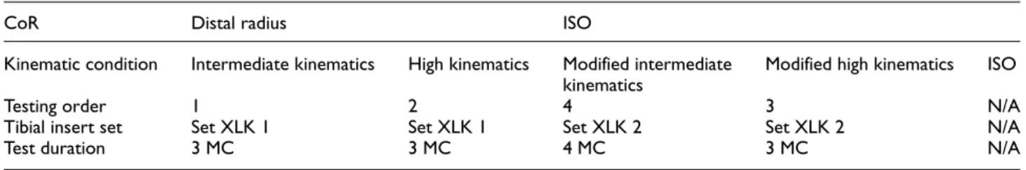
Table 2. Test order, duration and tibial insert set details for the XLKätibial inserts (n = 6 for each set).
CoR Distal radius ISO
Kinematic condition Intermediate kinematics High kinematics Modified intermediate kinematics
Modified high kinematics ISO
Testing order 1 2 4 3 N/A
Tibial insert set Set XLK 1 Set XLK 1 Set XLK 2 Set XLK 2 N/A
Test duration 3 MC 3 MC 4 MC 3 MC N/A
Consistent with previous studies,6,7,14,19 the distal-radius CoR was used with a polarity of anterior tibial shift (shown as negative AP motion in Figure 3) that produced femoral rollback. In studies using the ISO CoR position, it was necessary to reverse the direction of the AP displacement inputs in order to maintain the area of contact within the articulating region of the tibial insert. These kinematics were denoted ‘modified high’ and ‘modified intermediate’ kinematics for maxi-mum positive displacements of 10 and 5 mm, respec-tively (Figure 3). The resulting posterior translation of the tibia prevented femoral rollback.
An additional comparative study using the full ISO conditions taken from the 2004 version of the displace-ment control standard21(both CoR position and displa-cement profiles as shown in Figure 4) was conducted upon the conventional polyethylene (GVF) inserts. This was performed to further investigate the influence of simulation input conditions on the contact area, cross-shear and hence wear; specifically, the reduced amplitude and differing shape of the tibial rotation input profile compared to the Leeds profiles and the shape of the AP displacement profile.
All studies were conducted for a minimum period of 3 MC for each condition (Tables 1 and 2). The simula-tor was run at a frequency of 1 Hz. The lubricant used was 25% new-born calf serum supplemented with 0.03% (v/v) sodium azide to retard bacterial growth and was changed every 0.33 MC. Prior to testing, all inserts were soaked in deionised water for a minimum period of 4 weeks. This allowed an equilibrated fluid absorption level to be achieved prior to the commence-ment of the wear study reducing variability due to fluid weight gain. Wear of the tibial inserts was determined gravimetrically using a Mettler AT201 (Mettler-Toledo, Leicester, UK) digital microbalance, which had a read-ability of 0.01 mg. The volumetric wear was calculated from the weight loss measurements using a density of 0.93 mg/mm3for both polyethylene materials and using unloaded soak controls to compensate for moisture uptake.
Statistical analysis of the data was performed by first testing for homogeneity of variances and the means compared using the one-way analysis of var-iance (ANOVA) with 95% confidence interval. A post-hoc test was subsequently performed as appropriate using the Tukey’s test and significance was taken at p \0.05. This statistical analysis was performed using SPSS statistics (IBM SPSS, ver. 22).
Figure 1. Resulting distal and ISO position of the femoral CoR on a Sigma CR femoral component.
Figure 4. ISO AP displacement and tibial rotation input profiles.
Figure 3. AP displacement and tibial rotation input profiles.
Computational methodology
The computational framework corresponded directly with the experimental simulation. The computational model was further used to decouple the effect of kine-matic polarity and the position of the femoral CoR on the wear prediction. The computational wear model for the knee implants was based on the contact area (A), sliding distance (S) and an independent experimentally determined non-dimensional wear coefficient (C) to determine the wear volume (W). C was a function of cross-shear ratio (CSR).Wwas calculated according to the following equation31
W=C3A3S ð1Þ
TheCSRwas defined based on the unified theory of wear and frictional work by Wang33and the work by Kang et al.34to account for the strain hardening in the articulating polyethylene surface. The relationships between the non-dimensional wear coefficient andCSR
were determined from independent experimental pin-on-plate wear studies by Kang et al.34and Abdelgaied et al.35 for conventional and moderately cross-linked UHMWPE materials, respectively. These independent experimental pin-on-plate studies determined the mate-rial wear coefficient as an input to the model.
Conventional and moderately cross-linked UHMWPE materials were modelled in ABAQUS (ABAQUS 6.12-2) using stress–strain data supplied by the manufacturer (DePuy International, UK) as
isotropic elastic–plastic36 and isotropic elastic materi-als, respectively. The modulus of elasticity and Poisson’s ratio were taken as 463 MPa, 0.4637 and 673 MPa, 0.465for conventional and moderately cross-linked UHMWPE, respectively. A mesh sensitivity study resulted in a total number of elements of 42,777 for the tibial insert using modified quadratic tetrahe-dral elements (C3D10M). The femoral component was modelled as a rigid body.38 Isotropic penalty contact was used to define the surface-to-surface contact between the tibial and femoral contact surfaces with a coefficient of friction of 0.04.36 The computational model was run for 3 MC for each condition. The out-put sliding distances and contact areas were used to cal-culate theCSR and therefore the volumetric wear rate in mm3/MC. The computational framework is described more extensively elsewhere.31
Results
Preliminary experimental studies using the ISO femoral CoR position and standard Leeds high kinematic test conditions (AP anterior tibial shift of 10 mm) resulted in the contact between the femoral bearing and insert moving outside the articulating region of the tibial insert. This effect was also demonstrated through the computational contact modelling (Figure 5), and hence, the direction of motion for the AP input kinematics for the ISO position of the femoral CoR was reversed in
order to maintain contact within the articulating region of the insert.
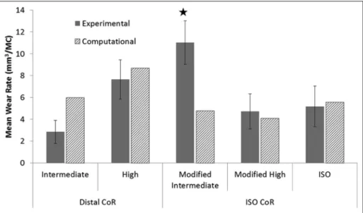
The position of the femoral CoR and the input kine-matics were shown to have a significant influence on the experimental wear rates of the GVF inserts (Figure 6) (p \0.05 ANOVA). The mean wear rate with 95% confidence limits on the distal CoR with high kinematics, with AP motion polarity producing roll-back (7.661.8 mm3/MC) was significantly higher than the ISO CoR position with modified high kinematics (4.761.6 mm3/MC; ANOVA, p \0.05). In addition, increasing the kinematic level through doubling the magnitude of the AP displacement on distal CoR from intermediate to high kinematics increased the wear rate significantly from 2.961.1 to 7.661.8 mm3/MC, respectively (ANOVA, p \0.01). In contrast, increas-ing the kinematic level on the ISO CoR from inter-mediate to high kinematics significantly decreased the wear rate from 11.061.9 to 4.761.6 mm3/MC, respec-tively (ANOVA, p\0.01). However, this result should be treated with caution, as the experimentally measured high wear rate for the ISO position of the femoral CoR and modified intermediate kinematics was partly attributed to damage of the contact surface and sub-surface cracking of the GVF inserts. This was suspected to have occurred due to oxidative degrada-tion in line with the age of the inserts (Figure 6). There was no significant difference between the modified high and ISO kinematic conditions under the ISO CoR posi-tion (ANOVA, p .0.05), with a wear rate of 5.261.9 mm3/MC observed under ISO input kine-matics. The moderately cross-linked XLK inserts showed similar wear rate trends to those of the conven-tional GVF material (Figure 7). The XLK experimen-tally measured wear rates under different kinematic conditions and position of the femoral CoR conditions
were, however, lower than those of the GVF material for all conditions (Figures 6 and 7).
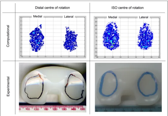
The mean wear scars at the completion of experi-mental simulation under distal/high and ISO/modified high kinematics were compared qualitatively (Figure 8). The experimental and the computational studies showed that the wear scars under the ISO/modified high kinematic conditions were located more anteriorly than the distal/high scars.
the position of the femoral CoR from ISO position to distal (under modified intermediate kinematic inputs polarity, that is, posterior tibial shift) did not, how-ever, affect the predicted wear rate (4.9 mm3/MC under ISO femoral CoR compared to 4.8 mm3/MC under distal femoral CoR).
The computationally predicted contact area through-out the gait cycle for the GVF inserts for all test condi-tions is summarised in Figure 10. In addition, the computationally predicted average wear rates andCSR
for GVF inserts for all test conditions are summarised in Table 4.
Figure 8. Comparison of wear scars at completion of study for distal and ISO CoRs after high and modified high kinematics, respectively.
Figure 9. Effect of kinematic polarity and position of the femoral CoR on the predicted wear rate, cross-shear ratio and contact area throughout the gait cycle under intermediate kinematic inputs for the GVF material.
Figure 10. Predicted contact area throughout the gait cycle for GVF material.
Table 4. Computationally predicted average wear rates and cross-shear ratios for GVF inserts.
Test conditions (CoR/kinematics) Predicted average wear rate (mm3/MC) Predicted average cross-shear ratio
Distal/intermediate 6.0 0.0253
Distal/high 8.7 0.0505
ISO/modified intermediate 4.9 0.0057
ISO/modified high 4.1 0.0041
Distal/modified intermediate 4.8 0.0017
Discussion
This is the first study investigating the influence of knee simulation input conditions comprising the position of the femoral CoR, input kinematics and direction of motion on the wear of a fixed-bearing TKR using a combined experimental and computational simulation approach. The experimental and computational studies have both demonstrated the effects the change in the CoR position and kinematic inputs, and most impor-tantly the direction of the AP translation, had on the relative contact points between the femoral and tibial components and hence wear during a standard gait cycle (Figures 8–10). In order to maintain contact within the articulating region of the insert, when the position of the femoral CoR was changed from the dis-tal to the ISO CoR, the direction of the standard Leeds AP displacement required reversal. The change in the wear rate was therefore due to the combined effect of changing the position of the femoral CoR and the direction of AP motion. The computational simulation was used to decouple this effect and provide further information on contact area, contact location and rela-tive motion at the articulating surfaces.
Specifically, the experimental wear simulation showed that changing the kinematic inputs from inter-mediate to high kinematics, with maximum amplitudes of 5- and 10-mm displacement in the AP direction, respectively, significantly increased the mean wear rate under the distal CoR for both GVF and XLK insert materials. This increase in the wear rate with increase in the AP displacement was, however, not observed when the ISO CoR was used. Indeed, a reduction in the wear rate of 60% and 30% for GVF and XLK insert materials, respectively, was observed (Figures 6 and 7). This was confounded further by the require-ment to reverse the direction of AP motion in order to maintain the contact within the articulating area.
On the distal CoR, where the polarity of AP motion replicates rollback and moves the contact point poster-iorly (Figures 8 and 10), there was higher conformity between the articulating surfaces and therefore higher
CRSs. Under high kinematics, the contact extended posteriorly with an average CSR of 0.0505. While for intermediate kinematics, the contact extended less pos-teriorly with an average CSR of 0.0253 and hence resulted in lower wear. In contrast, on the ISO CoR with posterior tibial shift, the AP translation moved the contact point anteriorly with lower conformity between the articulating surfaces and therefore lower
CSRs. This had the effect of reducing averageCSRand wear when high kinematics and high AP motion of maximum 10 mm was applied (CSR= 0.0041), but resulted in a higher averageCSRand wear when inter-mediate AP of 5 mm was used (CSR= 0.0057). The
CSRwas not the only factor which controlled the wear performance. However, for the same CoR, the change in the contact area with the change in kinematic input
was not significant, and therefore, the effect ofCSRon wear was the dominant factor.
On the ISO CoR, changing the kinematics from a maximum 10-mm AP tibial shift and65°tibial rotation to ISO inputs of 5-mm posterior tibial shift and 22°/ + 6° tibial rotation produced similar wear rates for GVF inserts (Figure 6). The computational prediction for theCSRbetween these conditions differed by a fac-tor of 2, with the ISO conditions having the higher
CSR. The total contact area was, however, lower than that predicted under the condition of maximum 10-mm AP tibial shift and65°tibial rotation, and the net effect was therefore not significantly different.
The 2004 version of the ISO displacement control standard21 for knee wear simulation maintained the contact in the centre of the tibia and prevented femoral rollback, producing a lower cross-shear, lower wearing simulation, which will not replicate the range of kine-matic conditions and wear rates found clinically. A recently revised version of the ISO displacement control standard25has reversed the direction of the AP motion, with an anterior tibial shift of maximum 5 mm. This brings the AP polarity in line with the Leeds wave-forms, although the CoRs are still different. The polar-ity of the tibial rotation profile has also been reversed in the 2014 version of the standard compared to the previous. However, there may still be a need to consider the position of the femoral CoR to match the physiolo-gical set-up and replicate clinical motion (femoral rollback).
The dependence of wear on simulation input condi-tions as demonstrated in this study suggests that these conditions should be carefully controlled when com-paring the wear of different designs or materials. This appropriate level of control can be achieved through the use of displacement control simulation. Simulation using force control is associated with more variation in the delivered kinematics to the TKRs under test and hence more variation in wear, masking the differences between different designs and/or materials. Therefore, in order to determine wear when variables such as design or material are being studied, the variation in kinematics should be carefully controlled and the displacement control regime is a more appropriate way to achieve this.
Similar trends were shown for the moderately cross-linked material, although lower wear rates were found overall due to the higher level of cross-linking (Figure 7) in line with other studies of cross-linked tibial inserts.7,39
difference in wear rates between different kinematic conditions and different materials,4,6,7,10,14,17–19 with sample sizes of three being used by other groups.22,39 For cross-linked polyethylene where lower absolute wear rates are observed, the difference in absolute terms between different conditions becomes lower, and future work may need to consider increasing the number of replicates in the study, when investigating wear rates of less than 5 mm3. However, the clinical relevance of these small absolute differences in the lower wear rates becomes less. In several of the tests, the same compo-nents were used, meaning that the results may not have been strictly independent; it is possible that changes in the surface topography of the implants as a result of one test may have influenced the wear of another where the same set of components were used. However, their surface roughness was routinely measured at the end of each study to confirm that there were no significant changes to the surfaces and mitigate this risk.
In terms of limitations of the computational model, the experimental wear coefficients used as an input to the computational model were calculated from wear data obtained from multi-directional pin-on-plate stud-ies under constant loading conditions and against smooth counterfaces. Dynamic loading in a pin-on-plate wear test can increase the wear volume40 and hence the wear coefficient.32Additionally, it can be dif-ficult to obtain such smooth surface profiles on cobalt chrome femoral surfaces. Moreover, the model is only valid under specified loading conditions. For these specified conditions, the surface wear mechanism domi-nates. Other test conditions may be associated with higher contact pressures, meaning different wear mechanisms may therefore take place.5
Conclusion
The most important factor influencing the wear of the fixed-bearing knee replacement investigated in this study was the position of the relative contact point at the femoral component and tibial insert interface. This was dependent on a combination of many parameters including input displacement magnitudes, waveforms, direction of motion and femoral CoR. The influence of the simulation input conditions did not vary with the two materials investigated in this study, with similar trends observed for both conventional and moderately cross-linked bearing materials. This study provides fur-ther evidence and supports that in order to study vari-ables such as design and material in TKR, it is important to carefully control knee simulation condi-tions. This can be more effectively achieved through the use of displacement control simulation.
Declaration of conflicting interests
J. Fisher is a consultant to DePuy Synthes Joint Reconstruction, Invibio, Simulation Solutions and Tissue Regenix and share holder of Tissue Regenix plc.
Funding
This research work was supported by EPSRC, Innovate UK and BBSRC (IKC Medical Technologies), the Leeds Centre of Excellence in Medical Engineering (WELMEC, funded by the Wellcome Trust and EPSRC, WT088908/Z/09/Z), the EPSRC Centre for Innovative Manufacturing in Medical Devices and the Leeds Musculoskeletal Biomedical Research Unit (LMBRU), funded by NIHR. J.F. is an NIHR Senior Investigator. This research work was supported by DePuy Synthes Joint Reconstruction, Leeds, UK, who also supplied the components.
References
1. The NJR Editorial Board. 12th annual report of the National Joint Registry for England, Wales, Northern Ire-land and the Isle of Man, http://www.njrcentre.org.uk/ njrcentre/Portals/0/Documents/England/Reports/12th% 20annual%20report/NJR%20Online%20Annual%20Re port%202015.pdf
2. Dalury DF, Gonzales RA, Adams MJ, et al. Midterm results with the PFC sigma total knee arthroplasty sys-tem.J Arthroplasty2008; 23: 175–181.
3. Hooper G, Rothwell A and Frampton C. The low con-tact stress mobile-bearing total knee replacement: a pro-spective study with a minimum follow-up of ten years.J Bone Joint Surg Br2009; 91: 58–63.
4. Fisher J, Jennings L, Galvin A, et al. 2009 knee society presidential guest lecture: polyethylene wear in total knees.Clin Orthop Relat Res2010; 468: 12–18.
5. Abdelgaied A, Brockett CL, Liu F, et al. The effect of insert conformity and material on total knee replacement wear. Proc IMechE, Part H: J Engineering in Medicine
2014; 228: 98–106.
6. Galvin AL, Kang L, Udofia I, et al. Effect of conformity and contact stress on wear in fixed-bearing total knee prostheses.J Biomech2009; 42: 1898–1902.
7. Brockett CL, Jennings LM, Hardaker C, et al. Wear of moderately cross-linked polyethylene in fixed bearing total knee replacement. Proc IMechE, Part H: J Engi-neering in Medicine2012; 226: 529–535.
8. Utzschneider S, Paulus A, Datz JC, et al. Influence of design and bearing material on polyethylene wear parti-cle generation in total knee replacement. Acta Biomater
2009; 5: 2495–2502.
9. Abdelgaied A, Brockett C, Liu F, et al. Effect of back-side wear and bearing material on wear performance of rotating platform mobile bearings. Bone Joint J Orthop Proc Suppl2013; 95: 214.
10. McEwen HMJ, Barnett PI, Bell CJ, et al. The influence of design, materials and kinematics on the in vitro wear of total knee replacements. J Biomech 2005; 38: 357–365.
11. Affatato S, Bracco P and Sudanese A. In vitro wear assessments of fixed and mobile UHMWPE total knee replacement.Mater Design2013; 48: 44–51.
12. Affatato S, Grillini L, Battaglia S, et al. Does knee implant size affect wear variability?Tribol Int 2013; 66: 174–181.
13. Affatato S, Leardini W, Rocchi M, et al. Investigation on wear of knee prostheses under fixed kinematic conditions.
14. Jennings L, Bell C, Ingham E, et al. The influence of femoral condylar lift-off on the wear of artificial knee joints. Proc IMechE, Part H: J Engineering in Medicine
2007; 221: 305–314.
15. DesJardins J and Rusly R. Single flexion-axis selection influences femoral component alignment and kinematics during knee simulation. Proc IMechE, Part H: J Engi-neering in Medicine2011; 225: 762–768.
16. Zietz C, Reinders J, Schwiesau J, et al. Experimental test-ing of total knee replacements with UHMW-PE inserts: impact of severe wear test conditions.J Mater Sci Mater Med2015; 26: 134.
17. McEwen HMJ, Fisher J, Goldsmith AAJ, et al. Wear of fixed bearing and rotating platform mobile knees sub-jected to high levels of internal and external tibial rota-tion.J Mater Sci Mater Med2001; 12: 1049–1052. 18. Barnett PI, McEwen HMJ, Auger DD, et al.
Investiga-tion of wear of knee prostheses in a new displacement/ force-controlled simulator.Proc IMechE, Part H: J Engi-neering in Medicine2002; 216: 51–61.
19. Barnett PI, Fisher J, Auger DD, et al. Comparison of wear in a total knee replacement under different kine-matic conditions.J Mater Sci Mater Med2001; 12: 1039– 1042.
20. ISO14243-1:2009. Implants for surgery – wear of total knee-joint prostheses – part 1: loading and displacement parameters for wear-testing machines with load control and corresponding environmental conditions for test. 21. ISO14243-3:2004. Implants for surgery – wear of total
knee-joint prostheses – part 3: loading and displacement parameters for wear-testing machines with displacement control and corresponding environmental conditions for test.
22. Johnson TS, Laurent MP, Yao JQ, et al. The effect of dis-placement control input parameters on tibiofemoral pros-thetic knee wear.Wear2001; 250: 222–226.
23. Lafortune MA, Cavanagh PR, Sommer Iii HJ, et al. Three-dimensional kinematics of the human knee during walking.J Biomech1992; 25: 347–357.
24. Sutton LG, Werner FW, Haider H, et al. In vitro response of the natural cadaver knee to the loading pro-files specified in a standard for knee implant wear testing.
J Biomech2010; 43: 2203–2207.
25. ISO14243-3:2014. Implants for surgery – wear of total knee-joint prostheses – part 3: loading and displacement parameters for wear-testing machines with displacement control and corresponding environmental conditions for test.
26. Knight LA, Pal S, Coleman JC, et al. Comparison of long-term numerical and experimental total knee
replacement wear during simulated gait loading. J Bio-mech2007; 40: 1550–1558.
27. Archard JF and Hirst W. The wear of metals under unlu-bricated conditions. P Roy Soc Lond A Mat1956; 236: 397–410.
28. Barbour PSM, Barton DC and Fisher J. The influence of contact stress on the wear of UHMWPE for total replace-ment hip prostheses.Wear1995; 181–183: 250–257. 29. Maxian TA, Brown TD, Pedersen DR, et al. A
sliding-distance-coupled finite element formulation for polyethy-lene wear in total hip arthroplasty.J Biomech1996; 29: 687–692.
30. Willing R and Kim IY. Three dimensional shape optimi-zation of total knee replacements for reduced wear.Struct Multidiscip O2009; 38: 405–414.
31. Abdelgaied A, Liu F, Brockett C, et al. Computational wear prediction of artificial knee joints based on a new wear law and formulation. J Biomech 2011; 44: 1108– 1116.
32. Liu F, Galvin A, Jin Z, et al. A new formulation for the prediction of polyethylene wear in artificial hip joints.
Proc IMechE, Part H: J Engineering in Medicine 2010; 225: 16–24.
33. Wang A. A unified theory of wear for ultra-high molecu-lar weight polyethylene in multi-directional sliding.Wear
2001; 248: 38–47.
34. Kang L, Galvin AL, Brown TD, et al. Quantification of the effect of cross-shear on the wear of conventional and highly cross-linked UHMWPE.J Biomech2008; 41: 340– 346.
35. Abdelgaied A, Brockett CL, Liu F, et al. Quantification of the effect of cross-shear and applied nominal contact pressure on the wear of moderately cross-linked poly-ethylene.Proc IMechE, Part H: J Engineering in Medi-cine2013; 227: 18–26.
36. Godest AC, Beaugonin M, Haug E, et al. Simulation of a knee joint replacement during a gait cycle using explicit finite element analysis.J Biomech2002; 35: 267–275. 37. Bartel D, Rawlinson J, Burstein A, et al. Stresses in
poly-ethylene components of contemporary total knee replace-ments.Clin Orthop Relat Res1995; 317: 76–82.
38. Carr BC and Goswami T. Knee implants – review of mod-els and biomechanics.Mater Design2009; 30: 398–413. 39. Utzschneider S, Harrasser N, Schroeder C, et al. Wear of
contemporary total knee replacements – a knee simulator study of six current designs.Clin Biomech2009; 24: 583– 588.