ISSN 1018-5593
European Commission
¡-'- SÌ
The Community's research and
development programme on decommissioning
of nuclear installations (1989-93)
European Commission
II??:!
The Community's research and
development programme on decommissioning
of nuclear installations (1989-93)
Annual progress report 1993
Directorate-General
Science, Research and Development
ULSei
1994
PARI. MRCP, fctíWh,
* M »
N.C.EUR 15854 EN
Published by the EUROPEAN COMMISSION
Directorate-General XIII
Telecommunications, Information Market and Exploitation of Research
L-2920 Luxembourg
LEGAL NOTICE
Neither the European Commission nor any person acting on behalf of the Commission is responsible for the use which might be made of the
following information
Cataloguing data can be found at the end of this publication
Luxembourg: Office for Official Publications of the European Communities, 1994 ISBN 92-826-8401-6
ABSTRACT
This is the fourth annual progress report of the European Community's programme (1989-93) of research on decommissioning of nuclear installations. It shows the status of the programme on 31 December 1993.
FOREWORD
The following fourth Annual Progress Report summarises the activities of the European Communities R&D Programme on Decommissioning of Nuclear Installations for the year 1993. (Annual progress reports 1990, 1991 and 1992, see ref. /I/, 111 and ßl).
This programme was adopted by the EC Council in March 1989 14/ to find "effective solutions which are capable of ensuring the safety and protection of both mankind and its environment against the potential hazards in decommissioning"..
As a large number of older nuclear facilities will be taken out of service in the next ten years, the public, the industry and national regulations are becoming increasingly Concerned about the occupational doses, environmental hazards and the costs which could be incurred in the decommissioning of such plants. The European Community, well aware of these concerns, has since 1978 operated and financed research programmes in this field.
The 1989-1993 programme concerns the following areas:
A. Research and development projects concerning the following subjects: Area N° 1: Long-term integrity of building and systems;
Area N° 2: Decontamination for decommissioning purposes; Area N° 3: Dismantling techniques;
Area N° 4: Treatment of specific waste materials: steel, concrete and graphite;
Area N° 5: Qualification and adaptation of remote-controlled semi-autonomous manipulator systems;
Area N° 6: Estimation of the quantities of radioactive wastes arising from the decommissioning of nuclear installations in the Community.
B. Identification of guiding principles relating to:
the design and operation of nuclear installations with a view to simplifying their subsequent decommissioning,
the decommissioning operations with a view to making occupational radiation exposure as low as reasonably achievable,
the technical elements of a Community policy in this field. C Testing of new techniques in practice:
pilot projects, alternative tests, staff secondment.
The research is carried out by public organisations and private firms in the Community under cost-sharing contracts with the Commission of the European Communities. The Programme's budget for the five-year period 1989-1993 amounted to 33.8 million ECU. In 1993, further funds (5.8 million ECU) were made available to permit continuation of the most important projects during 1994 and 1995.
Work on the four pilot dismantling projects will therefore continue. Also during 1993, Part B "Identification of guiding principles" was completed and the report is due to be published in 1994.
V-Thecommonaction tocollect datarelevant to cost,occupational doses,working timeand waste arisings isnowafully operationalpart of theprogramme.
I ammostgrateful tothecontractorswhohaveproduced mostofthesubstanceofthisreportand whoprovided aparticular effort to makeitstimelypublication possible.
For its compilation and editing I wishto thank mycolleagues, Messrs R Bisci,ΚPflugrad and R Wampach.
ThisisprobablythelastannualreportofthethirdEUDecommissioningProgramme(1989-1993). In 1994, the annual report will be replaced by the Proceedings of the Third International Conference on the Decommissioning of Nuclear Installations (26-30 September 1994, Luxembourg),whichwillpresent thefinalstate ofthe programme's activities.
R SIMON
Head ofthe Programme
References
HI "TheCommunity'sresearchanddevelopmentprogrammeondecommissioningof nuclear installations (1989-1993)". Annual progress report 1990. EUR 14227.
HI "TheCommunity'sresearch anddevelopmentprogrammeondecommissioningof nuclear installations (1989-1993)". Annual progress report 1991. EUR 14498.
13/ "TheCommunity'sresearchanddevelopmentprogrammeondecommissioningof nuclear installations (1989-1993)". Annual progressreport 1992. EUR 15262.
/4/ CouncilDecision of 14March 1989adopting aresearch and technological development programme for the European Atomic Energy Community in the field of the decommissioning of nuclear installations. OJNo.L98,11.04.1989, p.33.
151 CommissionCommunicationconcerningtheresearchprogrammeonthedecommissioning of nuclear installations (1989 to 1993). Call for research proposals. OJ No. C 24, 31.01.1991,p.8.
CONTENTS
SECTION A: RESEARCH AND DEVELOPMENT PROJECTS Page
1. AREA No. 1: LONG-TERM INTEGRITY OF BUILDINGS AND SYSTEMS 1
1.1. Examination and long-term assessment of nuclear power structures 2
2. AREA No. 2: DECONTAMINATION FOR DECOMMISSIONING PURPOSES 9
2.1. On-line decontamination of complex components for unrestricted release,
using ultrasonic waves in a flowing aggressive chemical agent 10
2.2. Development and optimisation of an easy-to-process electrolyte for
electrochemical decontamination of stainless steel 17 2.3. Microwave system to scarify concrete surfaces
18 2.4. Decontamination of large-volume nuclear components using foams
24 2.5. Decontamination of an evaporator of a pilot reprocessing plant
(EUREX-Saluggia) using a chemical agent dispersed as fog 30 2.6. Decontamination technique using a dispersed chemical agent
36
3. AREA No. 3: DISMANTLING TECHNIQUES 39
3.1. Effectiveness and long-term behaviour of cleanable high efficiency aerosol
filters 40 3.2. Abrasive water jet cutting technique from the stage of laboratory into real
application 41 3.3. Steel cutting using linear-shaped charges
42 3.4. Evaluation of the segmentation by various cutting techniques (plasma torch,
arc saw, circular disc, etc) 47 3.5. Underwater thermal cutting techniques and associated remote-controlled
manipulator systems 52 3.6. Development of a plasma arc torch and control/monitoring technique for the
internal cutting of small bore pipework 59 3.7. Development of a steel cable to cut highly reinforced concrete with
minimised water consumption 62 3.8. Assessment of state-of-the-art CO laser technology as an improved
dismantling tool 63 3.9. Cutting of C02 primary circuit pipes of G2/G3 reactors using explosive
charges 64 3.10. Underwater laser cutting of metal structures
70
76 3.11. Optimisation of plasma torch electrode design for nuclear dismantling tasks
4. AREA No.4: TREATMENT OFSPECIFICWASTE MATERIALS:
STEEL,'CONCRETE AND GRAPHITE 79
4.1. Industrialscalemeltingoftritiumcontainingsteelfromnuclearinstallations
4.3. Treatmentandconditioningofradioactivegraphitefromnuclearinstallations
• • » • • • ■ • • • • • • Φ · · · * * · · · " · · " " "
4.4. Recycling of activated/contaminated reinforcement metal in concrete . . . .
80 4.2. Development of aprocess for volumereduction of contaminated/activated
concretewasteincluding pilotscaletestingwith activewaste 81
88
94 4.5: Investigationsonrecyclingofradioactivenonferrous aluminium andcopper
bymeltingprocess 95
5. AREANo.5: QUALIFICATION AND ADAPTATION OF REMOTE CONTROLLED SEMIAUTONOMOUS MANIPULATOR
SYSTEMS 101
102 5.1. Roboticsystem for dismantlingofthe process cellof areprocessing plant.
5.2. Design, construction and testing of a manipulator for removing slag, measuring temperature and taking samples during melting of radioactive
metal 109
5.3. Telerobotic monitoring, decontamination and size reduction system
TMDSRS 116
5.4. Adaptation and testing of a remotelycontrolled underwater vehicle
123 5.5. Testoflongrangeteleoperatedhandlingequipmentwithdifferent toolsfor
concrete dismantlingand radiationprotection monitoring 126 5.6. Underwater qualification of RD 500manipulator 128
6. AREA No.6: ESTIMATION OF THE QUANTITIES OF RADIOACTIVE WASTE ARISING FROM DECOMMISSIONING OF
NUCLEAR INSTALLATIONS IN THE COMMUNITY 135
6.1. Methodologytoevaluatetherisksofdecommissioningoperationsonnuclear
plants 136
6.2. Dosesdue to thereuse ofveryslightlyradioactivesteel
137 6.3. Quick measuring methods of radionuclides inmaterials and wastes during
decommissioning of nuclearinstallations 146 6.4. Radiologicalaspectsofrecyclingconcretedebrisfromdismantlingofnuclear
installations 152
6.5. Definition of reference levels for exemption of concrete coming from
dismantling 155
6.6. The characterisation and determination of radioactive waste from
decommissioning 156
6.7. Quantification of activity levels and optimisation of dose rate management
to prepare stage 3 decommissioning of gas-cooled reactors 157
6.8. Decommissioning costs for nuclear installations
162 6.9. Development of a prototype apparatus visualising on a screen the gamma
sources superimposed on the image of the vision field . . . . 163
SECTION B: IDENTIFICATION OF GUIDING PRINCIPLES
7.1. Principles, regulations and policies for decommissioning
7.2. Preparation of a decommissioning handbook ,
8.4. Pilot dismantling of the FBR-fuel reprocessing facility ATI. Dismantling of dissolution and extraction systems and of fission product storage tanks; decontamination and remote dismantling of concrete walls
170
171
SECTION C: TESTING OF NEW TECHNIQUES IN PRACTICE
8.1. Pilot dismantling of the WAGR. Dismantling of top bioshield refuelling standpipes, vessel top dome, heat exchanger, remote dismantling of hot box,
remote waste packaging 174 8.2. Comparative assessment of alternative underwater remote operation and
segmenting techniques for reactor vessel internals of KRB-A . . 178 8.3. Pilot dismantling of the BR3 PWR. Decontamination of a primary circuit,
realisation of cutting equipment, segmentation of all reactor internals . . . .
179
186 8.5. Pilot dismantling of the KRB-A BWR. Dismantling of contaminated
components of the reactor building and of activated internals of the reactor pressure vessel; development and application of concrete sawing and melt
encapsulation (onion package) 191 8.6. Decommissioning of the Risø hot cell facility
199
8.7. Final clean-up of the PIVER prototype vitrification facility: decontamination
of the hot cell 204 8.8. Destruction of contaminated sodium of the primary circuit of experimental
RAPSODIE reactor 205 8.9. Decommissioning of the JEN-1 experimental reactor '
207
8.10. Development of segmenting tools and remote handling systems and application to the dismantling of VAK BWR reactor pressure vessel
internals 214 8.11. Melting of ferritic steel arising from the dismantling of the G2/G3 reactors
at Marcoule in a furnace installed at the dismantling site . 221 8.12. Melting of alpha-contaminated steel scrap at industrial scale
225
-IX-8.13. Demonstration of explosive dismantlingtechniques of thebiological shield
of theNiederaichbach nuclear power plant (KKN) 230 8.14. Decommissioning of theB205fuel reprocessing plant
237 8.15. Large-scale demonstration of dismantling techniques under realistic
conditions onthe LIDO biologicalshield 242 8.16. Furtherdevelopmentandoperationofanautomatedlarge-scaleradioactivity
measurement facility for low-leveldecommissioning waste
8.27. Survey of decommissioning requirements for W E R reactors
249
8.17. Development, manufacturing, commissioning and testing of an automated device for the projection of chemical gels and its application to G2/G3
reactor pipes 250
8.18. Development and manufacturing of a facility for the decontamination by electro-etching and applicationto alpha radioactivewastefrom the "RM2"
installation 254
8.19. Development of a robotic system (TRT) for the removal of tubes from a Latina steam generator, with subsequent melting and radiological
characterization 258
8.20. Assessmentof decontamination proceduresfor WWER PWRs withaview
to minimize the generation ofwaste 263
8.21. Design and manufacturing of ateleoperated deployment system based on the "NEATER" robot, to remove the U2 drain line, Β14 Windscale
Laboratory 270
8.22. In-situ decontamination of the tube bundlefrom asteam generator of the
Dampierre PWR and subsequent waste treatment 275 8.23. Decommissioning of the drygranulation plant using machine assistance . .
280 8.24. Remotelyoperated underwater dismantlingbyplasma arc andcable sawof
a structure inaCOGEMA storagepond 286
8.25. Further development of a data base on cutting tools and associated filter
systems for dismantling (Joint study) 292
8.26. Collectionandtreatmentofspecificdatageneratedinlarge-scaledismantling operationwith aviewto theiruseforcost and doseestimates (Joint Study)
297
301
ANNEXI Listofpublicationsrelatingtotheresultsofthe 1979-83programmeon the
decommissioning ofnuclear power plants 307
ANNEXII Listofpublicationsrelatingtotheresultsofthe1984-88programmeon the
decommissioningof nuclear installations 311 ANNEXIII Listofpublicationsrelatingtotheresultsofthe 1989-93programmeon the
decommissioning of nuclearinstallations 317 ANNEXIV Members of the Management and Coordination Advisory Committee
"NuclearFissionEnergy -Fuel Cycle/Processing and Storage of Waste".. 319
X-IJST OF ABBREVIATIONS - CONTRACTORS· NAMES AND ADDRESSES
AEA-Culch. Atomic Energy Authority Technology Culcheth, Wigshaw Lane,
UK-Cheshire WA3 4NE
AEA-Culh. Atomic Energy Authority Technology Culham, UK-Abingdon,
Oxfordshire OX14 3DB
AEA-Harw. Atomic Energy Authority Technology Harwell, UK-Oxfordshire OX11 ORA
AEA-Wind. Atomic Energy Authority Technology Windscale, UK-Seascale,
Cumbria CA20 1PF
AEA-Winf. Atomic Energy Authority Technology Winfrith, UK-Dorchester, Dorset DT2 8DH
ARC Arc Kinetics Ltd, 38, The Fairway, UK-Daventry, Northamptonshire NNI 4NW
BAI Benelux Analytic Instruments, Vaartdijk 22, B-1800 Vilvoorde
BI Batteile Ingenieurtechnik GmbH, Düsseldorferstraße 9, D-65760 Eschborn
BNF British Nuclear Fuels pic, Sellafíeld Works B403, UK-Seascale, Cumbria CA20 1PG
BS Brenk Systemplanung, Heinrichsallee 38, D-52062 Aachen
Bureau A+ Bureau A+, Godsweerdersingel 87, NL-6041 GK Roermond
CEA-Cad. Commissariat à l'Energie atomique, Centre de Cadarache, B.P. N° 1, F-13108 St. Paul-lez-Durance
CEA-FAR Commissariat à l'Energie atomique, Centre de Fontenay-aux-Roses, 60 Avenue du
Général Leclerc, B.P. N° 6, F-92265 Fontenay-aux-Roses
CEA-Sac. Commissariat à l'Energie atomique, Centre de Saclay, F-91191 Gif/Yvette
CEA-Valrhô Commissariat à l'Energie atomique, Centre de la Vallée du Rhône, B.P. N° 171,
F-30205 Bagnols/Cèze Cedex
QEMAT Centro de Investigaciones Energéticas Medioambientales y Tecnológicas, Avenida
Complutense 22, E-28040 Madrid
COGEMA Cie Générale des Matières nucléaires, B.P. 270, F-50107 Cherbourg
COMEX Comex Nucléaire, 36 boulevard des Océans, F-13275 Marseille
DLR Deutsche Forschungsanstalt für Luft- und Raumfahrt e.V., Pfaffenwaldring 38-40, D-70569 Stuttgart
ENEA Ente per le Nuove Technologie, l'Energia e l'Ambiente, Viale Regina Margherita 125,1-00198 Roma
ENEL Ente Nazionale per l'Energia Elettrica, Via R. Rubattino 54,1-20134 Milano ENRESA Empresa Nacional de Residuos Radioactivos S.A, Calle Emilio Vargas 7,
E-28043 Madrid
ENSA Equipos Nucleares S.A., Plaza del Marqués de Salamanca, E-28043 Madrid EPC S.A. d'Explosifs & Produits chimiques, rue de la Dynamite,
F-13310 St-Martin de Crau
EWN Energiewerke Nord GmbH, Greifswald, D-17509 Lubmin
FHGF Fachhochschule Giessen-Friedberg, Wiesenstraße 14, D-35390 Giessen Framatome Framatome, Tour Fiat Cedex 16, F-92084 Paris-la-Défense
Goodwin Goodwin Air Plasma Ltd, Kernan Drive, UK-Loughborough, Leiston LEU 0JF
IND International Nuclear Decommissioning (BNF), Sellafield, UK-Seascale, Cumbria CA20 1PG
KA Kraftanlagen Aktiengesellschaft, Im Breitspiel 7, D-69126 Heidelberg
KEMA N.V. Keuring van Elektrotechnische Materialen, Utrechtseweg 310, NL-6812 ET Arnhem
KfK Kernforschungszentrum Karlsruhe, D-76344 Eggenstein-Leopoldshafen
KKWR Kernkraftwerk Rheinsberg, D-16831 Rheinsberg
KRB Kernkraftwerk RWE-Bayernwerk GmbH, Dr.-August-Weckesser-Straße, D-89355 Gundremmingen
LAINSA Limpiezas y Acondicionamientos Industriales S.A, El Payeter 13,
E-46008 Valencia
NIS NIS Ingenieurgesellschaft mbH, Donaustraße 23, D-63452 Hanau
NNC National Nuclear Corporation Ltd, Booths Hall, Chelford Rd, UK-Knutsford, Cheshire WA16 8QZ
Noell NoeU GmbH-Nuklear Service, Alfred-Nobel-Straße 20, D-97080 Würzburg
NRPB National Radiological Protection Board, Chilton, UK-Didcot, Oxfordshire OX11 ORQ
Radia Radiacontrôle, Route de Lyon 44, F-38000 Grenoble
RNL Risø National Laboratory, P.O. Box 49, DK-4000 Roskilde
RWE Rheinisch-Westfälisches-Elektrizitätswerk AG, Kruppstraße 5, D-45128 Essen
RWTHA Rheinisch-Westfälische Technische Hochschule Aachen, Reutershagweg 4,
D-52074 Aachen
SCK/CEN Studiecentrum voor Kernenergie/Centre d'Etudes de l'Energie Nucléaire, Boeretang 200, B-2400 Mol
SG Siempelkamp Gießerei GmbH & Co, Siempelkampstraße 45, D-47803 Krefeld Siemens- Siemens AG, Bereich Energieerzeugung KWU, Hammerbacherstraße 12-14,
KWU D-91058 Erlangen
Siemens-BEW Siemens AG Brennelementewerk, Rodenbacher Chaussee 6, D-63457 Hanau
SSP Stangenberg, Schnellenbach und Partner GmbH, Viktoriastraße 47, D-44787 Bochum
Taywood TNO
TÜV-Bay.
TÜV-SWD
TWI
UDA
UHIW
VAK
Taylor Woodrow Engineering Ltd., Ruislip Road 345, UK-Southall UBI 2QX Netherlands Organization for Applied Scientific Research, P.O.Box 155, NL-2600 AD Delft
Technischer Überwachungsverein Bayern e.V., Westendstraße 199, D-80686 München
Technischer Überwachungsverein Südwestdeutschland e.V., Dudenstraße 28, D-68167 Mannheim
The Welding Institute, Abington Hall, UK-Abington, Cambridgeshire CB1 6AL
Universidad de Alicante, Carretera de San Vincente del Raspeig s/n, E-03099 Alicante
Universität Hannover, Institut für Werkstoffkunde, Appelstraße IIA, D-30167 Hannover
Versuchsatomkraftwerk Kahl GmbH, Postfach 6, D-63796 Kahl/Main
SECTION A: RESEARCH AND DEVELOPMENT PROJECTS
1. AREA No. 1: LONG-TERM INTEGRITY OF BUILDINGS AND SYSTEMS
A. Objective
It has been proposed that the dismantling of nuclear installations be delayed for periods ranging from several decades to about a hundred years. Thereupon, the radioactivity having largely died away, dismantling would be easier and the radiation exposure of the dismantling personnel would be less. The objective of this area is to determine the measures required for maintaining shut-down plants in a safe condition and to assess the radiological consequences of costs.
B. Research performed under the previous programmes (1979-1988)
The research work has been focused on the following main subjects:
inspection of selected nuclear power plants and examination of materials as they exist therein, in order to determine the mode and pace of degradation;
methodology studies of the measures necessary for maintaining plants in safe condition and for keeping the necessary ancillary equipment operable.
C. 1989-1993 Programme
Research in this area should be pursued with a constant moderate effort, enlarging the data base and exploiting the growing experience, in order to establish confidence in long-term forecasts. This involves in particular:
collection of additional experimental data, eg repetition of past examinations after a time interval of about five years, in order to determine the rate of degradation and derive or check forecasting rules;
comparison of confinement methods applied at specific shutdown nuclear installations in Member States;
assessment of the merits of the Safe Storage option in the decommissioning of nuclear installations other than reactors.
D. Programme implementation
At the end of 1993, one research contract relating to Area No. 1 was at the stage of execution.
1.1. EXAMINATION AND LONG-TERM ASSESSMENT O F NTTHTFAP POWHR STRUCTURES
Contractor: TEL, SSP, NNC Contract No.: FI2D-0048 Work Period: April 1991 - March 1994 Proiect Manager: C C FLEISCHER, TEL
Phone: 44/81/575 46 82 Fax: 44/81/575 40 44
A. OBJECTIVE AND SCOPE
This work programme describes two separate activities. Taywood Engineering Ltd (TEL) and Stangenberg, Schnellenbach and Partner (SSP) will collaborate to perform the examination and long-term assessment of nuclear power structures, and National Nuclear Corporation Ltd (NNC) will separately assess the risk of rapid stress corrosion cracking of carbon/low alloy steel and intergranular attack of stainless steel components.
The first activity (TEL/SSP) will be directed towards substantiating and redefining predictive models of the mode and pace of deterioration of nuclear power plant structures. The planned work will comprise re-visiting of sites previously examined, obtaining additional experimental data and making further assessment. Furthermore, efforts will be made to include investigation at stations not previously visited within EC member countries. All results will be incorporated into a coherent data base and proposals for a planned inspection and maintenance system will be produced. There is also a need to identify means of monitoring and assessing the ongoing state of tendons and components of buildings and structures which provide protection to nuclear plant. Theoretical research will be conducted into the long-term behaviour of the prestressed concrete pressure vessel (PCP V) at THTR Schmehausen as an example. The results will be used to develop a monitoring programme for the PCPV. The planned work is a complement to contracts FI1D-0030, FI1D-0031 and report EUR 12758.
The second activity (NNC) will be directed towards prediction of the levels of nitric acid which will form in nuclear power plants being decommissioned and assessment of the consequences of such levels with respect to corrosion/degradation effects which could adversely influence subsequent component removal.
B. WORK PROGRAMME B.l. THL Work programme
B.l.l. Re-inspection of Nuclear Power Plants B.1.2. Extension to further Nuclear Power Plants B.1.3. Compilation of Systematic Data Base B.1.4. Planned Maintenance System Development
B.1.5. Prestressing Options Study in collaboration with SSP B.1.6. Monitoring Requirements for Prestressed Concrete. B.2. SSP Work programme
B.2.1. Development of a planned maintenance system, including long-term behaviour of materials and structured components
B.2.2. Study of parameters of a prestressed concrete vessel with regard to partial destressing B.2.3. Monitoring requirements for a prestressed concrete pressure vessel and recommendations B3. NNC Work programme
B.3.1. Design review
B.3.2. Prediction of nitric acid concentration B.3.3. Literature survey
B.3.4. Corrosion assessment B.3.5. Environmental control B.3.6. Further work.
-2-C. Progress of work and results obtained Summary of main issues
Testing and analyses have been completed on the results of surveys carried out at Berkeley, Bradwell, Wylfa, Trawsfynnyd, Hunterston and Dungeness nuclear power
stations. Data from these surveys and those carried out in 1988 on Bradwell, Wylfa, WAGR and Hinkley Point A has been entered into a proprietary software package for use as a database. The practical issues in the development of a planned maintenance system for nuclear power stations have been considered in the light of the survey findings. A desk study of the monitoring techniques available for prestressed concrete has been completed and a review report produced.
The concrete stresses under two adverse cases of geometrical partial destressing have been calculated and assessed together with the strain behaviour for the prescribed cases of prestressing loss. The analyses resulted in stress states, for which only in the case of complete geometrical partial destressing, contain some tensile stresses. The serviceability of the PCPV is, however, not considered to be adversely affected by these tensile stresses since the vessel contains a lot of surface reinforcement. A residual prestressing of approximately 25%, in the case of the THRT-PCPV, is sufficient to keep the vessel walls free of tensile stress zones. For the development of a maintenance system, theoretical investigations have been carried out to define a strategy which is based on inspection classes and intervals. Three categories being dealt with are, stability of the buildings or the structural elements, the leak-tightness of the vessel and the durability of the materials.
Defuelling of the reactors at Berkeley and Latina Power Stations have been performed in an atmosphere of dry air following the initial cooling down under CO2. Defuelling at Hunterston A is being carried out under a CO2 environment. Contrary to predictions, no significant quantities of nitric acid were detected in samples of air taken from within reactor 1 at Berkeley and there was no major nitrate contamination of either graphite or steel samples removed from inside the pressure vessel. The reactor environment currently favoured for decommissioning nuclear installations is air. Calculations have also been performed which show that similar rates of formation of nitric acid are likely to occur by radiolysis of moist air during the prolonged care and maintenance phase of decommissioning for Magnox, BWR and PWR plants.
Progress and results
1. Inspection of Nuclear Power Plants (B. 1.1.. B. 1.2)
Thesummaryofresultsinclude:
□ predictionsindicate that after 150yearsfromconstruction, approximately 65% of allareascouldstillbepassive(70%externaland60% internal)
□ Predicted times to activation for internal areas ranged from 44 years to well in excessof 1000years. Timesfor externalareasrangedfrom23 yearsto wellin excess of 1000years.
□ Measured levelsof chlorides withinthe concrete were lowin manyareas, making accurateprediction ofT0difficult. Predictions indicatethatasubstantialpercentage of
steelisunlikelytobecomedepassivatedwithin 150years.
2. Compilationofsystematicdatabase(B.1.3)
Results fromthe inspections undertaken in the preceding research and development CEC programme and this current programme have been entered into a commercially available software program. This software program can manipulate, sort, search and extract datausing simple instruction. Datafromadditional surveys can be added directly intothedatabaseandmanipulated asrequired. It shouldbeviewed asafirststagedatabase which can beupgraded to include maintenance requirements, monitoring intervals, costs etc.
3. Plannedmaintenancesystemdevelopment(B1.4)
The practical issues in the development of planned maintenance system for nuclear power stationshavebeen investigated and stagesinatypical system havebeen considered inthe light of the survey findings. It is essential to first define the objectives of such a system andthen to set upa database of survey results andfindingsin order to define the extent andinterval ofinspection andmaintenance. Considerableadvantage is to begained byfirstsubdividing thestructures intoelementsatgreatestriskor withthegreatest impact of failure. A detailed knowledge is required of the ageing mechanisms of structures, in order to predict their longevity. Substantial research has already been completed on the performance ofreinforced concretethat formstheprincipalstructural elements. Estimates oflife expectancyandcost ofmaintenanceneedto bemadefor the structural and building elements. The objective of the planned maintenance system must be to optimise the selectionandtimingofthevariousactivities.
4. Studyofparametersofaprestressed concretevesselÌB.2.2Ì
Using a modified creep function which takes into consideration the age of loading, mechanical analyses of an axisymetric model of the THTRPCPV have been made, spanning a postoperational period ofnearly 100 years. The concrete stresses under full prestressing, 50% prestressing of all tendons, full destressing and two adverse cases of geometrically partial destressing havebeen calculated and assessed. Likewise the strain behaviouroversuchaperiodhasbeenanalysedforthedescribed casesofprestressingloss.
The analyses resulted in stress states which, only in the worst cases of geometrically partial destressing, contain tensile stresses. Since these stresses are predominantly caused by stress redistributions they are not considered to represent a problem of load carrying capacity. It can be concluded that, although the serviceability of the PCP V is not affected adversely by these tensile stresses, since the vessel contains a lot of surface reinforcement, the prestressing should not be removed completely in the case of planned reduction of prestressing. A residual prestressing of about 25% in the case of the THTR-PCPV is sufficient to keep the vessel walls free of tensile stress zones.
The findings of the theoretical investigations have consequences on the development of a maintenance system. With regard to this, investigations have been directed towards finding a strategy which is based on inspection classes and intervals.
5. Monitoring requirements for a prestressed concrete pressure vessel and recommendations (B.2.3)
The recommendations deal with three aspects of monitoring, covering the stability of the buildings or the structural elements, the leak-tightness of the vessel and the durability of the materials. The first two usually are mainly dependent on prestressing, the latter one depends on material oriented facts.
The aim of the long-term controlled durability of the concrete at the THRT-PCPV should be controlled safety during the whole lifetime after decommissioning. Some representative areas could be chosen and the selected areas should be easily accessible. The areas should be chosen in such a way that they represent the influences of the environmental conditions. The actual condition of these areas should be recorded by data on concrete cover, carbonation depth and chloride penetration.
Because of the low stressing of the sections, the long-term stability of the PCPV is not put at risk. This will remain valid even when the prestressing failed regardless of the failure mode. From this very important finding it could be deduced that monitoring the prestressing state of the PCPV is not necessary. On the basis of earlier investigations of the THTR-PCPV it can be assumed that the leak-tightness of the liner will remain if the structural integrity of the vessel is guaranteed. This assumes that the liner material itself will work without damage over such a long lifetime. This fact should not remain unnoticed considering the long-term leak-tightness of the PCPV or any other vessel.
6. Prediction of nitric acid concentration (B.3.2Ì
Rates of formation of nitric acid when decommissioning Magnox, PWR and BWR plant, four years post shutdown have been estimated and comparative values of 113, 37 and 100ml nitric acid per hour respectively have been obtained.
It has been calculated that when air was admitted into the Berkeley reactors during the first year following the "end of generation" and defuelling commenced, nitric acid will have been formed at the rate of a few kilograms per hour. By the end of the first year when the gamma activity had decreased, the rate would have fallen to a few grams per hour and after ten years the rate of reaction will be down to 1 gram per hour.
Defùelling of the reactors at Berkeley Nuclear Power Station and Latina PS has been completed some time ago. Essentially this was performed in an atmosphere of dry air following the initial cooling down under CO2. The air environment at Latina had a controlled moisture level of 100 to 400 ppm which was then relaxed to 1000 to 1200 ppm on completion of defuelling; the latter was consistent with the moisture content of the air in the Berkeley reactors. Defuelling at Hunterston A continues, but in this plant a CO2 environment has been maintained virtually throughout the period from final shutdown.
Although predictions relating to the formation of nitric acid because of the radiolysis of moist air during defuelling indicated that significant quantities of nitric acid should have built up in the reactors, evidence from measurements at Berkeley NPS suggests levels much lower than expected. The total concentration of nitrate ions measured in samples of air drawn from the reactor atmosphere at Berkeley NPS was equivalent to 0.26 wpm nitric acid. Also, the weights of nitrate/nitrite in liquid extracts produced from specimens of irradiated graphite removed from a sample channel in reactor 1, were similar to the level measured from a control specimen of inactive "virgin" graphite. Similarly, the nitrate/nitrite levels measured on the surface of steel samples removed from the lower dome and upper dome regions inside the pressure vessel of reactor 1 although measurable, are not significantly different from values recorded on internal steel surfaces during the construction of the Advanced Gas Reactors at Heysham and Torness.
7. Corrosion assessment (B.3.4.. B.3.5)
There was no evidence of serious corrosion within the Berkeley plant when limited video inspection was carried out and this is consistent with the results of limited inspection undertaken at Latina. Nevertheless, the proposed corrosion and atmospheric monitoring scheme has been maintained at Berkeley PS and a similar approach is being considered for both Latina and Hunterston A.
In order to monitor general corrosion and possible stress corrosion cracking, samples have been positioned above and below the core in the reactor pressure vessel(s) at Berkeley. Temperature and gas sampling points are also positioned at five different vertical positions in the reactor vessel. These are monitored from above an empty charge standpipe and fuel channel using instrumentation incorporating a six-way valve, connected to a data logger. Similarly the temperature and atmosphere inside the lower gas duct and within insulation surrounding the duct are being recorded.
-6-υ o
o
100
90
80
-70
60
50
40
--30
20 +
10
0 0
Based on equal number of internal and external locations
Γ
Π EXTERNAL j
■ INTERNAL
20 40 60 80 100 120
Time to Activation (Years)
140 1000 >1000
FIGURE
1
-
MINIMUM
PREDICTED
TIME
TO
DEPASSIVATION
BY
CARBONATION
2. AREA No. 2: DECONTAMINATION FOR DECOMMISSIONING PURPOSES
A. Objective
The objective of this research is to develop and assess techniques for decontaminating surfaces of components and structures of nuclear installations that are past use. The main purpose of decontamination would be reduction of the occupational radiation exposure during dismantling of the contaminated item and/or reduction of the volume of radioactive waste.
B. Research performed under the previous programmes (1979-1988)
The following decontamination techniques have been developed and assessed: techniques using aggressive agents in liquid and gel-like form;
electrochemical techniques using various electrolytes;
hydromechanical techniques (high-pressure water lance, ultrasound); decontamination of concrete surfaces by flame jetting.
C 1989-1993 Programme
Research in Area No. 2 should be pursued with a reduced effort focused on selected techniques. As a new subject, the use of liquid chemical agents carried by a large volume of air, in the form of foam or fog, should be developed with a view to decontaminating large-volume systems. Thermal techniques for removal of concrete surface layers should be investigated from a more general and fundamental view than in the past.
D. Programme implementation
2.1 ON-LINE DECONTAMINATION OF COMPLEX COMPONENTS FOR ~~J UNRESTRICTPn EFT .FASH. USING ULTRASONIC WAVES IN A FLOWING
AGGRESSIVE CHEMICAL AGENT
Contractor: ENEL, Milano Contract No.: FI2D-0016 Work Period: July 1990 - October 1993 Proiect Manager: F BREGANI
Phone: 39/2/7224 30 46 Fax: 39/2/7224 39 15 (or 34 96)
A. OBJECTIVE AND SCOPE
Previous experiments made by ENEL on small valves, using aggressive chemicals, showed that zones with residual contamination remain inside the components.
The present work aims at solving this problem by enhancing the decontamination effectiveness with the action of focused ultrasonic waves. The main objective of the project is to set up and test in real conditions a new decontamination process based on the simultaneous use of ultrasonic waves and aggressive chemicals, with ultrasonic transducers applied outside the components.
This decontamination process, if its expected performances are confirmed, could become a useful tool in decommissioning activities. It should allow to increase the amount of decontaminable parts without having to spend many man-hours and man-Sv (thus, without dismantling before decontamination).
The project is based on experimental investigations, mainly at laboratory scale but also in plant scale. It is the continuation of work performed by ENEL in the framework of previous EC programmes on decommissioning (contract DE-B-005, report EUR 9303; contract FI1D-0002, report EUR 12878; contract FI1D-0023, report EUR 13255).
B. WORK PROGRAMME
B.l. Evaluation, selection and acquisition of special ultrasonic transducers to be applied to complex components from outside.
B.2. Decontamination tests on specimens and components in the PECO loop.
B.2.1. Preparation of the DECO loop for testing; selection and characterisation of test specimens and components from Garigliano BWR.
B.2.2. Decontamination tests on contaminated specimens.
B.2.3. Decontamination tests on valves: radioactivity measurements, decontamination factor evaluation and secondary waste assessment
B.2.4. Data analysis.
B-3. Decontamination and dismantling of a part of a real system of a nuclear power station B.3.1. Preparation of the system part to be decontaminated.
B.3.2. Initial radioactivity characterisation. B.3.3. Process design and configuration. B.3.4. Decontamination.
B.3.5. Dismantling and final radioactivity measurements. B.3.6. Evaluation of secondary wastes.
-10-C. Progress of work and results obtained Summary of main issues
The research activity of this year has been focused on the decontamination and dismantling of a carbon steel line at the Garigliano BWR power plant (B3) in order to demonstrate the effectiveness of the decontamination process under study. More in detail the selected line is a part of the by-pass at the inlet of the n. °4 preheater which has operated at 150 C and 1.7 MPa for 86000 EFPH. The line includes complex components such as valves, elbows, "T" joints. The hold-up volume is 112 1 and the contaminated surface 3.3 m2. The surface activity is mainly due to Co-60 which ranges from 1.9 to 10.9 Bq/cm2.
For this decontamination a formic acid 15% 4- hydrofluoric acid 3% solution has been employed, while the ultrasound (UT) transducers have been applied only on selected components, in order to allow a direct comparison with the action of chemicals and an evaluation of the effects of the ultrasounds. Radiometric measurements indicate that, where UT are applied, the residual activity is a factor 4 to 10 lower than on the components where only chemicals are active; moreover, where UT are applied, the residual activity is always less than 0.3 Bq/cm2.
Progress and Tesults
Decontamination and dismantling of a part of a real system of a nuclear power station (B.3) 1. Preparation of the system part to be decontaminated (B.3.1)
In order to perform the decontamination test the following actions have been implemented:
-removal of the thermal insulation;
-determination of the radius of curvature of pipes and valves for UT transducer application;
-auxiliary loop connection to the test system and UT trasducer installation on the components;
-utilities installation (industrial water, electric power, drains, etc.); -hydraulic test of the system and instrumentation check.
Due to the hazardous characteristics of the thermal insulation material (which contains asbestos) and to the contemporary presence of a radioactive field, the removal has been performed with special care by a specialized firm using glove bags. The work team was composed by 4 workers and removal operations have been completed in 6 hours. The volume of material removed is 120 dm3, approximately. Measured dose rates in the working area range between 1.8 and 2.2 uS/h. The total dose absorbed by the personnel is 64 uS*man. 2. Initial radioactivity characterization (B.3.2)
A piece of pipe has been cut downstream the line to be decontaminated in order to obtain 11 square samples (9 cm2 area) for the initial radiometric characterization. The surface activity ranged from 1.9 to 10.9 Bq/cm2 for Co-60 and from < 0.001 to 0.092 Bq/cm2 for Cs-137. The corresponding mean values (standard deviation) are: 5.30 (2.79) and 0.039 (0.026), respectively.
3. Process design and configuration (B.3.3)
The line selected for the decontamination is a part of the by-pass line at the inlet of
theη.4preheaterwhich hasbeenoperated at 150°Cand 1.7 MPafor 86000EFPH(fig. 1). The lineinclude complex components such asvalves, elbows, "T"joints; it hasan hold-up volume of 1121 and an internal contaminated surface of 3.3 m2, approximately.
Sinceallthecomponentsarein carbon steelorlow-alloyed steels,thechemicalsolutionused in thetest is HCOOH 15% + HF 3.0% optimized in the laboratorytests.
Inorder toallow a specific evaluation of the synergic action oftheultrasounds, thesystem canbedividedintwozones(fig. 2):thezone "A"where 11 transducersareplacedatselected pointsand zone "B"wherenotransducers havebeen applied.
The transducers are of theLangevine typeand theUT generator is capableto supply 3300 Wat afrequency ranging between 20and 40kHz.
Chemicals recirculation and process monitoring is insured through the auxiliary loop as shown in fig. 3. Twocarbon steel samplepipes (C-l and C-2) cut downstream elbow 3are inserted in thisloop in order to control process effectiveness.
4. Decontamination (B.3.4)
The decontamination has been performed according to the following operating procedure: phase 1:pre-washing (industrial water + UT); duration 30min.
phase 2: decontamination (flowing chemicals + UT);duration 2.5 hours phase 3:post-washing(industrial water + UT); duration 30min.
System draining and drying with air follows.
DuringallthetestphasestheUTfrequency hasbeen setat20-20.5 kHz,whilethe supplied power hasbeen 24W/cm2. Thefollowing on-line measurements have been performed:
- Co-60 activity on pipeC-l and C-2 by aNal scintillator (fig. 4); - temperature of the pipes at selected locations;
- ultrasound frequency and power.
5. Dismantling and final radioactivity measurements (B.3.5)
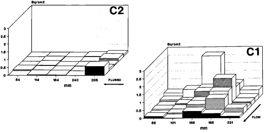
At the end of the test the sample pipes C-l and C-2 have been removed from the auxiliary loopand3*3cmsampleshavebeencutinordertoallowastatistical analysisofthe radiometricmeasurements. Similarlybothzone "A"and "B"componentshavebeen cutfrom the system to perform further radiometric measurements. Results of the residual activity distribution on pipe C-l and C-2 are reported in fig. 5, while all the residual activity measurementsaresummarized infig. 6. Itcanbenoted(fig. 5)thattheuseofUTdetermine amoreeffective anduniform removal oftheradioactivity; acomparison ofthemeanvalues bythe "t" test statistic indicate that the C-2 residual activity is significantly lower than the oneof pipe C-l, with aprobability error less than the0.5%.
Alltheradiometric measurementsindicate that, where UTare applied, theresidual activity isafactor 4 to 10lower than onthe components where only chemicals are active (fig. 6); moreover, where UT areapplied, the residual activity is always lessthan 0.3 Bq/cm2. Finally, data on the personnel absorbed doses during all the decontamination phases are summarized in tableT.
6. Evaluation of the secondary wastes (B.3.6)
Thespentsolution arisingfrom decontamination hasbeenstoredinawastetankwhere precipitation has been obtained raising the solution pH upto 8by Na(OH) addition. After precipitation theseparated sludgehasbeenheatedin ahoven at 85°Cfor twohoursinorder toobtainthesludgedewatering. Dataonspent solutiontreatmentaresummarizedintableTI.
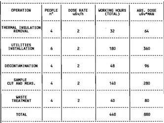
12-Table I: Personnel absorbed doses during all the decontamination phases.
OPERATION
THERMAL INSULATION REMOVAL
UTILITIES INSTALLATION
DECONTAMINATION
SAMPLE CUT AND MEAS.
WASTE TREATMENT
TOTAL
PEOPLE n°
4
6
4
4
4
DOSE RATE uSv/h
2
2
2
2
2
UORKING HOURS (TOTAL)
32
180
48
140
40
440
ABS. DOSE uSv*MAN
64
360
96
280
80
[image:27.595.165.499.102.353.2]880
Table II: Summary of the data on the waste treatment.
SPENT SOLUTION
VOLUME I ACTIVITY Bq/cm3 Fe (dissolved) g/l
AFTER PRECIPITATION (*)
SOLUTION ACTIVITY Bq/cm3 SLUDGE WEIGHT (**) 9 SLUDGE ACTIVITY Bq/g
175
0.17 4.25
0.09 1218 5.73
(*) NaOH up to pH 8
(**) After 2 h in a hoven at 85 °C
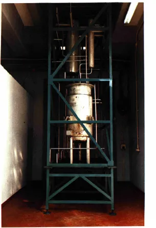
13-Fig. 1 View of the system selected for the field test at the Garigliano BWR plant
I
Hl·▼
▼
1 ' T 'CONNEC. 2 ' T 'CONNEC. 3 ELBOWS 4 ELBOWS 5 ELBOWS 6 VALVE4" 7 VALVE4" 8 VALVE6"
CONNECTIONTOTHE DECONTAMINATION
SYSTEM
c:_.
GASVENT
ULTRASONIC TRANSDUCER
Fig. 2 Scheme of the system selected for the field test at the Garigliano BWR plant
Ii n d u s t r i a l w a t e r I t a n k
filterL
w a s t e t a n k
chemicals t a n k
c f c
s a m p l eï p l e t Γ
ΐ
t e m p , d i s p l a y
UT generator
I— f c o u n t e r
legend
o thermocouple • UT transducer
Fig. 3 Operating scheme of the decontamination test at the Garigliano BWR plant
7000
Co-60 (cps)
6 0 0 0
-5000
4000
3000
2000
0 6 5 9 5
— CH+UT — · — CH
1 4 3 2 9 3
Time (min)
Fig. 4 On-line monitoring of the the activity on pipe C-l and C-2 during the test
-Bq/om2
Fig. 5 Residual activity distribution on pipe C-l and C-2.
C-1 PIPE
ZONE "B"(Complete)
ZONE "B"(Welding)
VALVE 7 (Wedge)
C-2 PIPE ZONE "A" (Complete)
ZONE "A" (Welding) VALVE 6 (Wedge)
VALVE 8 (Wedge)
0 0.2 Fig. 6 Summary of the residual activity measurements
ONLY CHEMICALS
0.53
CHEMICALS+UT
0.4 0.6 0.8 RESIDUAL ACTIVITY (Bq/cm2)
[image:30.595.78.514.409.702.2]2=2= DEVELOPMENT AND OPTIMISATION OF AN EASY-TO-PROCESS ELECTROLYTE FOR FIÆCTROCHEMICAL DECONTAMINATION OF STAINLESS STEEL
Contractor: KA, Heidelberg Contract No.: FI2D-0020 Work Period: July 1990 - June 1992 Proiect Manaper: A STERINGER
Phone: 49/6221/94 12 50 Fax: 49/6221/94 17 07
A. OBJECTIVE AND SCOPE
This work aims at optimising an acetyl-acetone base electrolyte so that it can be used for electrochemical decontamination of stainless steels. Kraftanlagen Heidelberg developed the electrolyte under the preceding EC programme from 1984 to 1988, (contract No. FHD-0004, report EUR 12383).
With regard to waste management and disposal, the obtained electrolyte came up to all expectations. An advantage of the organic electrolyte as compared to the phosphoric/sulphuric acid electrolyte is its long radiological service life (the activity settles out continuously). It is easy to convert the crystalline by-product (sediment) by high-pressure compaction into a form that is suitable for disposal. As only little residues of acetyl-acetonates are dissolved in the electrolyte, it is possible to considerably reduce the electrolyte volume by evaporation.
In tests with radioactive samples of carbon steel, the obtained results concerning removal effects, duration of treatment, surface quality, and decontamination factors, were satisfactory or good. However, pitting was observed in the tests with samples of stainless steel. As a consequence, the surface was not uniformly removed. Parts of the original surface were visible for a long time. This resulted in poor decontamination factors or long treatment times, respectively. In addition, larger volumes of secondary wastes were produced than with a uniformly removed surface. It is therefore required to optimise this electrolyte, if it is to be used for the treatment of stainless steel.
B. WORK PROGRAMME
B.l. Quantitative investigations concerning the dissolution mechanism
B.2. Optimisation of the aqueous electrolyte through replacing the potassium bromide by other conductive salts.
B.3. Investigations into scattering and its effect on abrasion, surface quality and decontamination factor.
B.4. Development of a water-free electrolyte.
B.5. Decontamination tests with contaminated samples. B.6. Processing of spent electrolyte.
C PROGRESS OF WORK AND RESULTS OBTAINED
This project was completed in 1992. The final report is being prepared for publication.
17-23. MICROWAVESYSTEMTOSCARIFY CONCRETESURFACES
Contractor: ENEA,Casaccia ContractNo.: FI2D-0024
Work Period: January 1991-December 1993 Proiect Manager: Ρ CORLETO
Phone:39/6/30484055 Fax:39/6/304839 51
A.OBJECTIVEAND SCOPE
For the decommissioning of nuclear installations, it may be necessary to scarify masonry or concrete walls, removing at least 20-25 mm of plaster or concrete, in order to eliminatetheincorporatedcontamination.Amongtheavailabletechniques,theonebasedonthe effect ofmicrowavesuponthewatercontainedincementisveryinteresting;thewater evaporates and the steam pressure within the pores shatters the cement in smallsplinters. This method is suitablefor remote operation andproduces noliquid effluents.
The research project concerns a microwave system consisting in a bell for the. scarification and the suction of the splinters and inasupport structure for thebell, compatible withtheremotehandlingsystemsavailableattheITRECplant.Thesystemwillbe manufactured, set upand tested at theITRECplantinTrisaiaonnon-radioactive and onradioactive concrete surfaces.
As regards the innovative aspects of the research programme, it is intended to optimise theinterconnection between themicrowavegenerators,develop an efficient system to containandcollecttheparticulate,improvetheefficiency oftheparticulatefiltrationand, finally, render thewholesystemflexible andeasily operated.
B.WORKPROGRAMME
B.l. Design andconstruction of aprototypemicrowavesystem B.2. Designandconstruction ofthesupport structure.
B 3 . Trialoperations on anon-radioactiveconcretewalL
B.4. Testingoftheprototype on aradioactiverycontaminated concrete surface.
18-C PROGRESS OFWORKANDRESULTS OBTAINED
Summaryofthemainissues
The microwave system, designed and manufactured in 1991,wassubjected, after tests performed in 1992,to several modifications in order to improve the system:the previousrigid waveguideswerereplacedwithflexibleones andthe adherenceof thesuctionbell'sskirt to the surfaceduringoperationwasincreased. In1993,testswereresumedtoestablishthe performance oftheupgraded system andto determinethetemperaturedistribution intheirradiated concrete and the influence of theconcrete's characteristicson the scarification efficiency.
Thetests on theradioactivelycontaminated surfaces werecarried out eventually.
Progress andresults
1. Design and construction of aprototype microwavesystem (B.l.)
The main modification consisted (see Fig. 1) of three 6 m flexible wave guides, which replace theprevious rigidonesconnecting the microwave generators to the irradiation heads.
Consequently, theboxcontaining themagnetrons isnot fixed to the irradiation heads and can be positioned independently, far from the suctionbellcontaining the irradiation heads, and alsooutsidetheradioactively contaminated areaifdesired; moreover, themobilityof thesuction bellisgreatlyenhanced. Theflexiblewaveguideshavearectangular section (95 mmχ45mm), a minimum bending radiusof 300mmand aloss in thetransmitted power that does not exceed 0.085dBper m.
Another modification implemented to improve the transfer of the debris to the vacuum system envisaged dividing the suction bell's skirt in vertical mobile sectors kept in contact by means of springswith thepossiblyirregular concrete surface.
2. Design and construction of asupport structure (B.2.)
A special mobile tablewasconstructed, connected to the existingcarriage of the support structure. This table, to which the suction bell with the irradiation heads is fixed, can be positioned transversally with respect to the direction of the carriage's movement; the lateral excursion obtainable is600mm,and allowsthe production of three contiguous furrows without movingthe supportstructure. Employing thetable, also, theirradiation heads and the bell can be rotated by 90°, to test the application of microwaves with the heads in series instead of in parallel. Furthermore,thetablecan be movedverticallyto attain irradiation headstand-offs up to 100mm. Lastly, anindicator for thestand-off is foreseen.
3. Trial operations on anon-radioactive concretewall(B.3.)
All tests on the microwavesystem were carried out at ENEA's Trisaia Research Centre; thoseon non-contaminated concretewere performed inthe Technological Hall.
Efficiency of theflexiblewave guides -Fifty testswere performed with theflexiblewave guides; an examination of the data (s. Table I) showed no significant difference on the scarification efficiency dueto theflexiblewaveguides. AsFigure2shows,thefurrows obtained werecontinuous andwell-defined, their areaand depthdidnot change andalsothequantity and the removal rate of the debris were unvaried, reaching respectively 9 kg and 6 cm3/s. Slight losses of microwaves and correspondent increases in temperature were found in localized spots alongthewaveguides;these spotsdepended mainlyuponthe layout of thewaveguides and not on themicrowave power being transferred.
Characteristicsoftheconcrete. Theconcretecharacteristicswereexamined (density,water content andwater/aggregateratio,porosity,permeabilityto air,compressionstrength, superficial hardness,etc.)to determinetheirinfluence ontheresultsof thescarification. Other parameters considered were thesizedistribution of thedebris particles and the modification of the cement structure after microwave irradiation.
19-For thispurpose,inadditionto thetwolargeslabs(3mχ2.5mχ0.17m)havingthe same characteristic!(asregardscomposition,additives,lebarsetc)oftheconcreteusedinthebuilding oftheItalian powerstations,severalsmallslabs(0.8mχ 1mχ0.2m)werebuilt,using different typesof cement andvarying amounts ofwater,sandandaggregates.
The analysesshowedthat themainfactors affecting scarification are:the pore dimensions and the evaporable water in the cement. Small pores favour the shattering of the cement, probablydiminishingtheresistanceofthecementstructuretothesuddenpressurerisedueto the irradiated water vaporizingwithinthe pores.
Thesclerometric(superficial) hardnesswhichisalsoindicativeoftheporedimensionsisan important parameter to consider inevaluatingthe liability to scarification of cementslabs.
Evaporablewater in the cement includes that bonded to thecement ashydrogel and the free water present inclosed and open pores;thiswater, measurablebythe lossof weight after 24h in an oven at 105°C, must be above a certain limit (about 2%) to allow an efficient scarification.
Asregardstheother parametersconsidered, thedebrisparticlesdonot present significant differences insizedistribution forvariouscompositionsof theirradiated material;andno change appears inthe cementstructure measured bymeans ofX-raysbefore and after scarification.
Temperature measurements-Thepurposeistodeterminethetemperaturedistribution on thesurface and inside theslabsduringscarification. Forthesurface measurements,an infrared videothermographic camerawasused;for thetemperatureinsidetheslabs,thermocouples were positioned around the slabs at various depths (3.5, 7, 10.5 cm). Data was collected at predetermined timeintervals,memorizedonafloppydiskandreproducedseparatelyingraphical form.
4. Testing of theprototypeon aradioactivelycontaminated concretesurface (B.4.)
The system was tested on radioactively contaminated surfaces in the Hot Cell for Mechanical Operations,named"Corridor", oftheITRECPilotReprocessingPlant attheTrisaia Centrewithsatisfactory resultsbothasregardstheremovalofthecontaminatedconcreteandthe containment of radioactivity.
Figure 3showsafurrow resultingfrom thescarification inthe 'Corridoi''.
Table II presents themain data relevant tothe activityperformed inthe radioactive area. Inconclusion,itmaybestatedthatthemicrowavescarificationsystemisareliableapparatus capable of continuous scarification rates, efficient containment andremovalofdebris.
Nevertheless, the system in its present state could be further developed to improve its flexibility and facility of operation.
•20-TABLEI:COLDTESTSONCONCRETE S U B S
ro
test N-of 1 2 1 1 2 2 1 2 3 124a 124b 1 2 4 125a 125b 125 126a 126 127a 1 2 7 128 129 130a
1 3 0 131 1 3 2 133a 1 3 3 1 3 4 1 3 6
Day 12 12 12 12 1 2 12 12 12 12 12 12 13 13 13 13 13 14 1 4 1 4 1 4 1 4 1 4 1 4 Slab
OPC3250,6* 325F/B 325F/B OPC3250.6 OPC3250,6 OPC3250.6 OPC4250,6 OPC4250.6 OPC4250.6 OPC425S ' OPC425S OPC5250,6 OPC5250.6 OPC5250.6 OPC425S OPC4250.8·
OPC4250.8 OPC4250.8 OPC4250.8 OPC4250,4* OPC4250.4
CA-S 42SA0,4* Humidity % 2,80 1,20 1.20 2.80 2,80 2,80 2,60 2,60 2,60 2,90 2,90 3,20 3,20 3,20 2,90 2.80 2,80 2,80 2,80 2,10 2,10 0,40 0,80 Power kW 16 16 16 16 16 16 16 16 16 16 16 16 16 16 16 16 16 16 16 16 16 16 16 Stand olf mm 15 15 1 5 + 3 0
1 5 15 15 15 15 15 15 15 15 16 15 15 15 15 15 15+2.5 15 15 15 15 Affrancameli rata mm/esc 1.68 1,68 1.68 0 0 1.68 0 0 1.68 0 1.68 0 1,68 1,68 1,68 1,68 1,68 1,68 1,68 0 1.68 1,68 1,68 Rsnected Power Kw 4,5 3,5 4,4 3 3,5 4 4,5 4,8 4 3,5 4 3,8 4 4 3,5 3,5 5 3.5 3,7 3,5 3,7 Energyleakage cm0-50-100(slab
mW/cmq 100-20-1 100-20-1 100-18-1 100-18-1 100-18-1 8-0,2-0,1 60-3-0,4
6 0 - 2 - 0 . 4
Energyleakage cm0-50-100(guides
mW/cmq
60-1,8-0,2 20-2-0,6 60-2-0,2 6 0 - 2 - 0 , 2 25-2-0,8 2 0 - 1 - 0 , 7
65-2-0,3 80- -0,2 80-1-0,2
80-3-0,6
Temperature
legiblewaveguides (η·1-2-3)"C
5 4 - 8 8 - 1 6 9 6 2 - 1 0 1 - 2 3 1 6 2 - 1 0 1 - 2 3 1
6 6 - 1 2 0 - 1 6 7 5 5 - 6 6 - 6 1 3 8 - 5 5 - 1 7 5 6 8 - 4 5 - 1 3 0 3 5 - 5 0 - 1 3 5
5 0 - 7 0 - 2 0 5 6 3 - 8 0 - 2 5 0 5 0 - 4 5 - 6 1
5 0 - 9 0 - 3 1 5
Dimensionofthe Debris furrows Kg Ixlxhcm 75x21x3 90x21x3 92x23x6,5 8x16x1 9x18x2 64x23x3x 60x20x3 62x22x2,5 62x22x2 64x17x2,5 66x18x2,5 70x18x5,5 65x18x2 6,100 9,200 3,200 4,800 4,900 6,000 5,800 4.400 4,900 3.250 1,400 3,000 Ν·οί explosion 6 3 3 0 9 2 5 3 2 6 0 4 6 3 4 5 3 5 4 9 4 5 2 5 1 0
N o t e
photo 131415/13 t1:1' s t o p ^ O "
t1:28" stop:10'04"
over test 122 t1:3' stop:11'35"
11:0 stop:1'03" test for temperature measurement
over test 124a t1:0 stop:1'30" test temp measurement.
over test 124b e 124a t 1 2 0 " stop:9'45"
t1:0 stop:40"
photo 1920/13 over test 125a t1:0 stop: 2'30"
photo 21/13 over test125b e 125a 11:35" stop: 6'
t 1 : 0 stop: V24"
photo 2324/13 over test 126a t1:40" stopfi'58"
photo 2526/13 t1:0 stop:2'30"
over test 127a 11:2' stop:8'20"
photo 2728/13 t1:40" stop:8'40"
photo 28/13 1120" stop:6'54"
over test 130a 11 : s t o p :
t1:45" stop:7
photo 2930/13 over test 13111: 36" stop: 6'50"
t1 : 0 stop:40'
photo 32/13 M: 30" ;stop:7· discontinuous farrow
11: 2' stop:T XV. 3' stop:1V LEGEND ; · Uto dala of the reflected power, ol the energyleakageand ofthetemperature is themaximumone found
11» lime elapsed between carriage onset and magnetron startup stop ■ time elapsed from magnetronstartup
Table lit Radioactive area scarification results Test* N ' 142 143 144 Humidity % 1,3 1,3 1,3 Power kW 15,2 16,2 16,2 Stand off mm 15 15 15 Advancement Rate mm/s 1,66 1,26 1,68 Reflected Power kw 3,3 3,5 2,6 Dimensions ofthe furrow
ΙχIχhcm
60x20x1,5 25x20x1,5 40x20x2 Weight kg 2,340 2,056 2,528 Activity before Bq/g 2,43 3,18 119,4 Activity after Bq/g 0,14 0,22 6,1 Decontamination factor* % 94 93 94,8 Activity indrums
(Cs1 3 7)
103Bq
187,2
191,4
252,8
* determined with respect to activity before scarification
•22-Figure
1
:
Flexible
wave
guides
ην**·*, e?τ-c s â ^ . ac
«■' 1
tf
r
,rJ
|1
Ffr/i
JMW/MM
^^mmmmmmmM
Â*
m
Wl^EflP
%\ 'M
^
f
ι ¿i^^^¿^„j»«··—^""■~*
·* ' —
y
Al
1
M
^H^^^^H
Bt''^*Λ.
Η Β Η
^ —
^ — ¿~»
« ^
^
■'
Ι
f
i
Λ»
l i »
· ·
'm-ft ø»
Λ
Figure
2
:
Test
128
Figure
3
:
"Corridor"
scarification
2A DECONTAMINATION OF LARGEVOLUME NUCLEAR COMPONENTS USING FOAMS
Contractors: CEACad,AEAWinf ContractNo.: FI2D0035
WorkPeriod: October 1990December 1993 Coordinator: J Ρ GAUCHON, CEACad
Phone:33/42256193 Fax:33/42253545
A.OBJECTIVEAND SCOPE
There areonlyafewmethodsfor insitudecontamination ofverylarge components usually in complex forms, such as large valves, reservoirs, heat exchangers, turbines, vessels, boilers.
The foam application processes have the major advantage of using only small quantitiesofliquidandbeingabletoforcefully penetrateeverywhere.Suitablechemicalreagents are added to the foam,which actsadynamiccarrier.
In thiscontract, a technique of permanent foam circulation willbe sought, so that decontamination canlast for severalhoursinordertobeaseffective aspossible andto useonly aminimum amount ofliquid.Decontamination factors ofover 100are expected.
The objectives oftheprogramme areto:
develop anddemonstrate aneffective insitudecontamination techniquefor largevolume components usingchemical foams containingdecontamination reagents;
minimise the volume of secondary wastes produced and demonstrate a treatment and disposalroute,e.g.electrolyticprocesses,wetoxidation.
B. WORK PROGRAMME
B.l. Chemicalfoamformulation containingdecontamination reagents (CEA) B.2. Foam production and developmentof acirculationsystem (CEA)
B3. SmallpOottests toqualify thedecontamination method (CEA) ΒΑ Secondarywastestreatment (AEA)
B5 Design,constructionandoperationofaprototypefoamproductionandcirculationripnon radioactivedemonstration (CEA)
B.6. Industrial application: decontamination of a 1000 m ' graphitepas cooler from the decommissioningsite ofG2/G3(CEA)
C. PROGRESS OFWORK ANDRESULTS OBTAINED
Summary of main issues
Feasibility tests were conducted on a pilot installation at Cadarache, proving that the foam process could beimplemented onanindustrial scale. The operating conditions suited to the decontamination of the Winfrith deaerator were established. Nevertheless, the annoying withdrawal ofthe AEApartnersobliged CEACad to findanother suitablenuclear component to demonstrate theeffectiveness ofthefoam decontamination technique onanindustrial scale. After preliminary tests, CEACad successfully conducted the decontamination of a gascooler from thedecommissioning site ofG2/G3 atMarcoule.
Proeress and results
1.Chemical foam formulation containingdecontamination reagents (Β.1Λ
The initial sulphuric formulation planned for Winfrith was no longer adequate since the materials involved in this new project were different. The gascooler was made of ferritic steel and brass. It was therefore necessary to modify the descaling foam to have comparable erosion levels for the brass and the ferritic steel. A sulphonitric mixture gave thebest results.
No rinsing foam was planed for Winfrith. Instead, a water spraying was proposed. Nevertheless, it seemed pitiful tö loose all the benefit in terms of minimising the secondary wastes during this last treatment. Therefore additional tests were conducted to finalise a rinsingfoam formulation.
2.Foam production anddevelopment ofacirculation system ΓΒ.2Λ
Feasibility tests conducted on a 2,lm3 pilot unit proved that the circulation of the fluidswas mastered and thatthe processcould beimplemented onan industrial scale.
3. Smallpilot teststo qualify the decontamination method (B.3.)
Decontamination testswere conducted on samples cut from asimilar gascooler being dismantled. The treatment retained was applied in three steps: a degreasing, adescaling and a rinsing step according to the modified foam formulations. The results obtained confirmed the effectiveness ofthe foam technique interms of decontamination.
4. Secondary wastetreatment 03.4.)
The treatment of the effluent was our partner's responsibility (AEA, Winfrith). No progress report hasbeen communicated thisyear.