DEFLECTIONS IN THIN CYLINDRICAL SHELLS
with particular reference to the buckling deformations of shells loadedin axial compression.
by
COLIN GEORGE FOSTER M.E.
Submitted in fulfilment of the requirements for the degree of
DOCTOR OF PHILOSOPHY
in the
Faculty of Engineering UNIVERSITY OF TASMANIA
AUSTRALIA.
I hereby declare that, except as stated herein, this thesis does not contain any material which has been accepted for the award of any other degree or diploma in any University, and that to the best of my knowledge and belief, this thesis does not contain a
copy or paraphrase of material previously written or published by any other person, except when due reference is made in the text of this thesis.
--) /1/. •
CONTENTS. PAGE.
Preface.
Additional publications. Acknowledgements.
Chapter 1. Introduction-buckling in thin Walled 1. cylinders.
Chapter 2. A new theory for the buckling of thin 34.
.cylinders in axial compression.
Chapter 3. An examination of the conventional 81. solution method for the axial
buckling problem.
Chapter 4. Finite difference solution of the 107. partial differential equations.
Chapter 5. Extensions to the space frame model 126. for the collapse of cylinders
loaded in axial compression.
Chapter 6. An experimental technique for measuring 168. radial deformations.
Chapter 7. Experimental evidence to support the 192. space frame theory.
Chapter 8. Conclusions. 230.
Appendix A. Results of combined load buckling 242. tests.
Appendix B. Results of finite difference- solution 280. of partial differential equations.
Appendix C. Program listing for buckling analysis 316. of cylinder as a space frame
and typical output.
Appendix D. Program listing and typical output of 320. programs used in the finite
difference solution of the deflections in a cylindrical shell with a geometrical defect.
Appendix E. • Program listing and typical output of 344. programs used in calculating the
fold shape based on the bi-harmonic equation.
Appendix F. Program listing and typical output of 354. programs used in calculating the
PREFACE
deformations would be large enough for buckling to be a consideration. However, the nature of the buckling process must be understood to determine when it is important.
In Chapter One the general nature of the known experimental buckling behaviour is described. The discussion is not limited to axial compression but includes torsion and hoop compression as well as combinations of all three. Experimental results are included that show the interaction between these modes and indicate possible weaknesses in existing design data.
Chapter Two is probably the most important chapter of the thesis and forms the basis on which the
remainder is built. In this chapter a new theory is presented to describe the buckling behaviour of cylinders. For this
theory the cylinder (both in the pre-buckled and post-buckled state) is replaced by an equivalent space frame with the
members tracing the folds in the Yoshimura pattern. The buckling problem is then reduced to a buckling analysis of the substituted space frame. The results from this analysis agree remarkably well with published information on
post-buckling behaviour.
In Chapter Three an examination of the Donnell equations is made. These equations were meant to
inadequate. It appears that second derivatives of out of plane displacements (curvatures) may need to be included as additional terms.
A finite difference solution of the partial differential eauations is conducted in Chapter Four. This analysis has shown that inclusion of the curvature terms could account for a 15% change in calculated values even in the pre-buckling range for which the calculation was stable.
Some refinements to the space frame theory are considered in Chapter Five. It is shown-that considering the member as initially curved leads to more confusion than any possible advantage it could have. However, the analysis allowing for the curved member is included since it is
probably the most obvious condition where improvement would be expected. It is hoped that others will, profit by the experience and not follow the same reasoning. It is also shown that the aspect ratio of the lobes in the buckled cylinder varies with the radius to thickness ratio. When this variation is taken into account the agreement
is not unreasonable between predicted buckling loads and published experimental results for cylinders.
In Chapter Seven the experimental method is used to determine the size of some defects in experimental
ADDITIONAL PUBLICATIONS
The following papers have been published covering work described in this thesis.
Measurement of radial deformations in thin-walled cylinders. Experimental Mechanics. Vol.18, no.11, Nov:1978. (Chapter 6)
Some observations on the Yoshimura buckle pattern for thin-walled cylinders. J.of Applied Mechanics. Vol. 46 1 no.2, June 1979. (Chapter 2)
Estimation of the collapse loads of thin-walled
cylinders in axial compression. J.of Applied Mechanics. Vol.46 1 no.2, June 1979. (Chapter 2)
The following papers have been written and are at present being reviewed.
Interaction of buckling loads in thin, walled cylinders. Submitted to Experimental Mechanics. (Chapter 1)
A note on curvature and twist measurements using the Ligtenberg-moire . method. Submitted to Strain.
(Chapter 5)
The effect of shell wall flexibility on the collapse of thin walled cylinders loaded in axial compression. Submitted to J.of Applied Mechanics. (Chapter 5)
ACKNOWLEDGEMENTS
No piece of worthwhile research could be concluded without the assistance of many people. To all those that have helped in any way the author would like to express his gratitude. Special acknowledgement is recorded for the following.
Professor A.R.Oliver and Dr.R.F.Rish. -- The supervisors for the project.
Mr.Basil Stiberc and the other workshop staff who made all of the apparatus used in the experimental
investigations.
and
CHAPTER
HNTRODUCTION
CHAPTER 1
INTRODUCTION -- BUCKLING IN THIN WALLED CYLINDERS
The work that is described in this thesis originated in an enquiry from industry about the design of cylindrical shells particularly with regard to buckling. The particular cylinder involved was relatively thick walled and would yield before the deformations had grown sufficiently for buckling to be a problem. However, when investigating the buckling situation the work described in this thesis evolved.
A classical buckling load can be obtained for thin walled cylinders loaded in axial compression as explained in Timoshenko and Gere-(ref.1--pages 457-458).
3.
This classical analysis assumes axisymmetric failure in a
or ,e'etafriga/a, pfive /0.07.Yer., ripple pattern A and is expressedas:-
dea
c E,T
R13(1-v2 )} *
It is well known that the "ripple" pattern illustrated in figure 1.1 occurs only in relatively thick walled shells where yielding has first occured. If the cylinder collapses 'elastically then the buckle pattern is a series of diamonds as shown in figure 1.2. , Even more important is the fact that the nominal stress at collapse is considerably below that value given by equation 1.1. This discrepancy has led to a great deal of research both experimentally and theoretically. The experimental work is largely summarised in a paper by Harris et.al .(ref.2). That paper statistically analyses the available experimental data to establish 90$ confidence limits for design purposes. On the theoretical side, a major contribution was made by Von Karman and Tsien in 1941 (ref.3), based on eouations published by Donnell in 1934(ref.4). They considered the post buckling behaviour of the cylinder and allowed for large deflections by taking second order geometry terms into account. In their work the graph shown in figure 1.3 was derived, here reproduced from FlUgge (ref.5). Many researchers refined the calculations of Von Kaman and
Tsien and with the advent of digital computers the solution technioue could be extended. Yoshimura (ref.6) showed the diamond pattern obtained in buckling to be a folded,
developable surface and eventually Hoff ,Madsen and Tiayers (ref.7) concluded that the whole Donnell-Von Karman and
4.
FIGURE 1.1
INELASTIC AXIAL RIPPLE BUCKLING
No. 2011 ALUMINIUM CYLINDER R=12.7mm. T=0.5mm.
FIGURE 1.2
[image:15.562.16.551.16.782.2]NOMINAL AXIAL STRAIN
FIGURE 1.3
THEORETICAL BEHAVIOUR OF AXIALLY
COMPRESSED CYLINDER
[image:16.565.69.473.50.740.2]6.
Tsien approach was inappropriate. Using an'infinite series solution they came to some rather startling conclusions which are reproduced here,as follows.
"In the limit as the number of terms in the series expansion) tends to infinity, the exact Yoshimura pattern is approached on the basis of an extrapolation of the results obtained with the aid of a digital
computer. In this limiting case N(the number of
circumferential lobes) approaches infinity, the amplitude of the displacements tends to zero, the Von
Karman-Donnell equations are rigorously valid, the T/R ratio approaches zero, and the value of the average axial stress capable of maintaining equilibrium in the postbuekling state is zero."
Clearly a solution which leads to conclusions of this nature can not possibly describe the real
situation. Anyone who has ever folded a sheet of paper into a Yoshimura pattern is well aware that the structure so formed has considerable strength. The theory developed in the next chapter is an attempt to overcome the
difficulties mentioned above. It does appear to supply a reasonable explanation of the buckling behaviour of thin walled cylinders in axial compression.
7. the graph shown in figure 1.3 proposed that an imperfect cylinder would follow the path shown by either curve A or curve B. Curve A represents a cylinder with a small defect while curve 7 represents a cylinder with rather large
defects. In both cases the collapse load is considerably reduced from the theoretical value (the classical load). Thus defects in shape have a considerable influence on the collapse load of axially compressed thin walled cylinders.
Buckling due to bending is very similar in nature to axial compression so that the same type of
argument would apply. For failure due to torsion the reduction in critical stress (due to imperfections) from the classical value is not as severe but is still
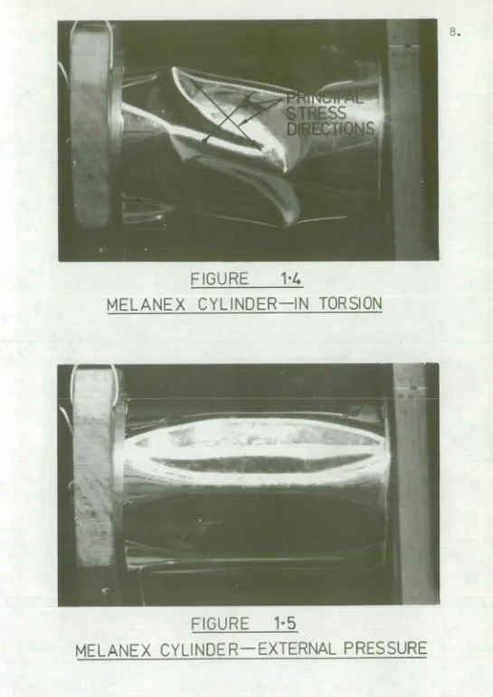
substantial. Collapse from external pressure loading is even less ausceptable to imperfections. Figures 1.4 and 1.5 show the type of buckle pattern obtained in torsion loading and from external pressure.
For the reader interested in further reading on the stability of shells two excellent review articles are available (refs. 8 and 9).
B.
FIGURE
1.4
MELANEX CYLINDER IN TORSION
FIGURE
1-5
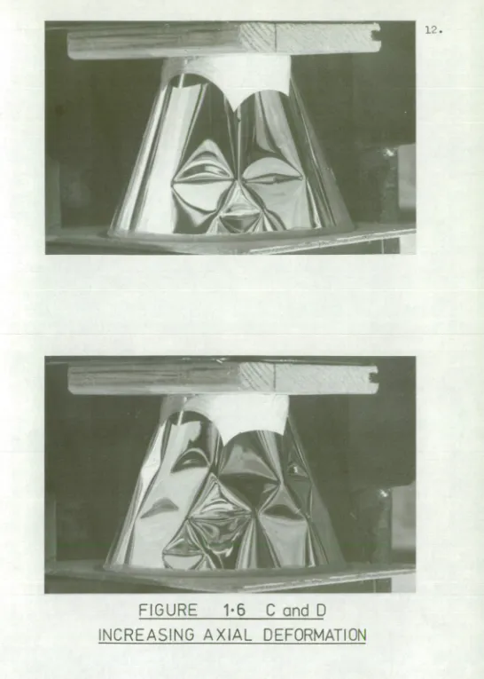
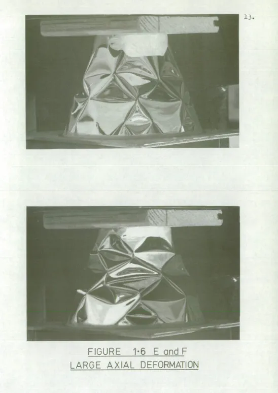
on the shell. Figure 1.6 shows the growth of the buckle pattern with increasing axial strain on a conical shell made of 0.1mm. thick melanex. The shell was 76mm. long,
45mm. dia. at the all end and 106mm. dia. at the large end. The behaviour of conical shells is very similar to cylindrical shells in axial compression. In figure 1.6A an imperfection can be seen that serves as a nucleation Point for the diamond pattern. In subsequent photographs the diamond pattern is seen to spread from this point and intensify as the axial displacement is increased.
Even though the large discrepancy is known to exist between theory and practice, cylindrical shells are used as structures, partiaularly in the aerospace industry. Thus design formulae
must
be available. One source of these formulae is Roark(ref. 10) but these formulae need to be treated with caution because of the age of the reference. Another, more modern source is Baker, Kovalevsky and Rish (ref. 11) which is based on the NASA "Shell Analysis Manual"(ref. 12). A summary of these design formulae is given in table 1.1. This last reference is essentially for use in the aerospaceindustries where shell structures would normally be more perfectly made than the fabricated one from which this investigation started. Thus the size of the imperfections here may make the design formulae useless. To test this hypothesis a melanex cylinder was made and tested. The manufacture of the cylinder was deliberately crude so that imperfections would be large. The cylinder was
10.
TABLE 1.1
. DESIGN FORMULAE FOR CALCULATIOF OF CRITICAL STRESSES
Mode Source Formula Comments
Axial
Compression
Roark = E.T Classical formula-"actual" value 0.4 to 0.6 of calculated value.
Cr cr
2)R
Baker
Kovalevskya- &Rish
r.E.T tread from graph. allows for
imperfections. cr=
R /3757723 Axial Compression Internally Pressurised Baker Kovalevsky &Rish.
( r
cr cr + =s , AC'as above. c read from graph. "1.3(1-1/ 2)
liC e )ER.T
Torsion Roark rer=--7ET 2/
(
y) 0.6 + 1-V -
d7.80.0.S9N41) iic,vbe rg.
"Actual" value 0.6 to 0.75 of
calculated value.
B
ig:Ievsky &Rish.
E.T Irer=C8-71. 8R Z4 Z= L21---7
C read from graph. s
* ITT -V
Torsion Internally Pressurised Baker Kovalevsky &Rish E.T ICr =cs---7R.Zr + 4
E.T AC
AC s read from graph.
s R External
Pressure
Roark
or
= 0.801-Cr
1T%--2N i 14-
(1-)2 ) 3 R2
Baker
Kovalevsky &Rish.
K ..2 .E
,e _ 13 .4 (TI2 Kp read from graph.
11.
FIGURE
1-6
CONICAL SHELL IN AXIAL COMPRESSION
UNDEFORMED SHELL
12.
FIGURE
1.6
C and D
13.
14. 127mm. long, 89mm. dia. and had a wall thickness of 0.1mm. A longitudinal seam was made by butting the two ends of the melanex together and lapping the joint with cellulose adhesive tape. The ends of the cylinder were bonded to
brass reinforcing rings with contact cement. This cylinder collapsed elastically so that repeated tests were possible on the one cylinder. A simple loading rig was made
(figure 1.7) such that the cylinder could be tested with combinations of axial load, torsion and internal vacuum since the magnitude Of the external pressure needed to collapse the cylinder was very small. The apparatus
could also be internally pressurised to test the stiffening effect that internal pressure has on the .stability of the cylinder in axial compression and torsion. :Because of,the nature of the Apparatus the weight of the crosshead was always present as an axial load. Thus for torsion loading and hoop compression the measured values would be slightly lower than the actual critical loads.
The measured nominal stresses at collapse are given in table 1.2 and compared with the values obtained from an application of the design formulae. In applying the design formulae values of Young's modulus and Poisson's ratio were required. Because of the nature of the test material a great deal of difficulty was experienced in
measuring these quantities. Young's modulus was eventually measured at 5.6GPa. but this value could not be guaranteed
to better than about
5%.
Poisson's ratio measurements were hopeless so that a value of 0.35 was guessed. This value has only a small effect on the calculations so thatTest
Cylinder
Sleeve Grease
Seals
1-1 2 mm Limit of travel of crosshead
Crosshead
Vacuum Connection
Torsion Loading
15.
[image:26.568.62.522.70.751.2]Axial Load
FIGURE 1.7
16. variation in the calculated value of buckling stress. The value of 0.35 was assumed on the basis that both persDex and araldite have values around this figure.
A glance at table 1.2 will show that, as anticipated, the design formulae for axial compression
gave values that are too large for this particular cylinder. Thus it could be assumed that the imperfections in shape are much larger in this relatively crudely made cylinder than the design formulae allow. In the case of torsion loading the design formulae could be considered as just adequate. Imperfections do not have as large an effect in torsion as with axial compression which could account for this improvement. With hoop compression, the design
formulae appear quite safe. In this case imperfections have the least effect on stability. By internally
pressurising, the stiffening of the cylinder for both axial compression and torsion greatly exceeded the design figures. The photograph shown in figure 1.2 is this
cylinder under axial compression. The diamond pattern is well establiShed with the axis of the diamond at right angles to the more negative principal stress
17.
Figure 1.8 illustrates the buckling modes for various combinations of loading and in each of these photographs the principal stress directions are marked to illustrate the orientation of the buckle pattern. A summary of the measured nominal stresses at collapse for this
cylinder in all the test conditions is given in table 1.3. These values are plotted in figures 1.9 and 1.10 to
illustrate the interaction between the various buckling modes. In figure 1.9 the interaction between torsion
and axial compression is illustrated while in figure 1.10, torsion is used as the parameter of the graph of the
interaction between axial compression and hoop compression, i.e. figure 1.9 appears as the Y axis in figure 1.10.
Baker, Kovalevsky and Rish ref. 11) give a
general relation between buckling modes as,
=1 1.2 Where A,B and C are the ratios of the
nominal stress at collapse in the combined case for a particular mode,to the nominal stress at collapse if the cylinder was to buckle in that mode only. They then go on to establish values for the indices in two combinations,
ea 7- 2
dF"57
0. (Ti;)
=1
1.3and Oh
Cra
c Crhc
a)
a)
-ri
•
0 ca -1-> 43) cd A H -P G) F-4 $4 o T3 41 g to 4-1 4-) to ad a) A j4 3 a) IO A 4. 3 cd a) a) ad 0 qz, 0 • a) -,-1 g co 0 ri -P a) cd a) ri Ca 02 bf) 0 a) 0 -Cl C41
-1- 54
(ll C.) U) .0 H 61 -r-t cd cd o Cl) -rt zi 0 -P o 0 .1-I a) c13 $.1 Ca -P 0 Si o P• •El Cl) Pi a) •r-i 0 0 r-1 § a) cel cd a)
0 - 4
s imi lar to Pe rsp ex and Araldite
calculations.
T17
7
STRV, S...1:i AT C OLLAI'SE ..1 P
.-
C.:
P•
-
I
0. 23I 1 I I0H H e• 1 0,-) H I 1 I t cv NI • H000 op H • ..o H • H NZ
0. 2 0 -]
_ I 1 I i I 1 I I t- N 00 1/40 N 0 IAD 0 IN -I 0 ,..- cf H • 0 I 1 lO - r Cl I ,--1 I I 0 I cn .,") 0 -.I (--- 0 • 0 -.." t- 0 • 0 en kl) 0 0 en kr , 0 • 0 I I I I i I 1 I *---r H • 0. 14
0. 4 0
0. 0741 --; Ct _ • 01 H • I I 1 H • 0. 43
0. 43
11
0.076 ,
\CI C --- 0 • 0 UN In 0 0 tc ■ In 0 o I 1 t I I I I I 0. 13 H 0. 44 V3 C-- 0 . 0 0I
0. 9 81
ci — ko C-- • H .4 - en • H
2. 3 8
N N • H 0. 75 01 I.0 • 00 CO en •
0. 4 6 I
1 1 I I H lf1 • 0
0.6 8 _1
0. 6 8
1. 80 k.0 01 • 0 ' cd iiI.1 - H cn • 0 * * H 0 • H H CI 0 2. 45 2. 45 0. 60 0. 60
0. 3 6
0. 3 6
in
•
0. 5 4
0. 5 4 I 1 •
ON rn H 0 VD • 0' , 4 ..- c3 ill .--. 0. 82 t I 1 I 0. 82 I ko I 1 cI VD • N 0. 90 0. 90 0. 5 8
0. 5 8
I ---7
0. 90 01 • 0 0. 90 H . N 0. 90 A co C!, U--: to 03 H P-, • _. H in 01 • H 0 -% CO r 4. 77 9. 24
4. 2 0 I
vp in • NHHHN rn t---- 0 en ko 0 H 0 -) . • 1. 33 <7% 0 • t-I 1. 19 3. 17
2. 5 9
re! f...• -L-0 lapa 2. 62 * * in In • 2. 62 H ■ 0 CO • H ;IN in
5. 81
2. 43 2. 43 0. 93 0. 93 4. 65 en 0 -1 • 0 en cr) • 0 0. 93 2. 62 2. 43 CH
4...H..._r
11
-Pa
- 3. 10
I I I I 0 H • in I
[ 16. 7
43. 6
N
%.0
H
11 2. 95
2. 95 1. 55-
1. 55 4. 65
in
iN
H
r
1. 5 5L
2. 95 3. 10cr; 1-4 ClJ co co co co V) • un HHHIXDC ....3 HHHHHHHO3 n.: n: CV %0 CO CO CO • • CV NI N NI VD • til C--I -4 - RI 1 S1 0 in 0 CO :r CO 01 CO 1/40 C--- in t--. •a - H H (00 0 NO I.0 al 01 01 co 00 (v 00 in tO Cn 01 Cyl --4- k.0 CC) a) -a - a - • H C-- I.(1 In Ln in CV CV CV CV en HHH HHHHHH in in 1.C1 IN in N CV N .4 .4 . IA irk ii-■ in cr) H 0 • 0 C-I H 0. 1 0. 025 0. 075 0. 025 0. 05 0. 05 0. 05 0. 05 0. 15 0. 05 0. 05 0. 05 0. 1 0. 05 In • a- A C73 H cn p-- rsf 1:-' i >-, I-1 :--) .7- ■ ln 1.N In Ill 4 - • • . 1- •:1 - -a - .4 N .:1 - In ln In • • • N .4 4 - .4 - Ill 111 I.IN LC \ •.i . • . .:1 - 4 - .4 .4 N i.11 in On "- In C\ I N N LC \ in rq rq In in 0000 O. 111 1.1.1 Ln In rn en rn rq
o O 8 8
In In In In Lil rq rq in rel rn
8 o o 8 o
o-
0
---- -0.86MPa. 0h-=0
T=
0.39MPa.
19.
cr
a
=-0.68MPa. al
l
=-0-148MPa. 7=0-19MPa.
FIGURE 1.8
cr0 =-0•68MPa. 0)-1 7::- 0-044 MPa.
7
-
=0•78MPa.
20.
o-a 7---0-68MPa. a'h=-0 -201 MPo. T=0
FIGURE 1.8
cr0 =-0-05MPa. crh= -0.113 MPa. 7'=0.88MPa.
[image:32.564.8.551.17.796.2]a--0 r--1.17MPa. 0--h =+0-179MPa. T=1•17MPa.
FIGURE 1.8
TABLE 1.3 22. Eiciria STRESSES AT COLLAPSE FOR CYLIEDER EO.I
cra
crh
•
7"
A1 A
2 A3 A4
TIPa MPa rPa
-1.16 0 0 1.00 1.00 1.00 1.00 -0.88 0 0.19 0.79 0.84 0.79 0.84 -0.86 0 0.39 0.89 0.99 0.89 0.99 -0.75 0 0.58 0.98 1.10 0.98 1.10 -0.44 0 0.78 0.99 1.09 0.99 1.09 -0.05 0 0.98 1.00 1.00 1.00 1.00 -0.05 -0.231 0 1.00 1.00 1.00 1.00 -0.96 -0.144 0 1.04 1.04 1.16 1.16 -0.68 -0.148 0.19 0.90 0.95 1.01 1.06 -0.68 -0.144 0.39 1.01 1.11 1.11 1.20 -0.68 -0.096 0.58 1.05 1.17 1.13 1.24 -0.68 -0.044 0.78 1.22 1.33 1.25 1.35 -0.68 -0.201 0 1.05 1.05 1.17 1.17 -0.40 -0.201 0 0.94 0.94 1.01 1.01 -0.40 -0.192 0.19 0.94 0.99 1.01 1.06 -0.40 -0.166 0.39 0.95 1.05 1.02 1.11 -0.40 -0.153 0.58 1.08 1.20 1.15 1.26 -0.40 -0.105 0.78 1.18 1.28 1.23 1.33 -0.05 -0.231 0.19 1.04 1.09 1.04 1.09 -0.05 -0.205 0.39 1.04 1.14 1.05 1.14 -0.05 -0.179 0.58 1.11 1.23 1.12 1.23 -0.05 -0.135 0.78 1.19 1.30 1.20 1.30 -0.05 -0.113 0.88 1.27 1.34 1.27 1.34 -1.95 +0.179 0
x unpressurised o 0.4 k Pa Internal
Pressure
21.
NOMINAL SHEAR STRESS AT FAILURE (MPa)
0•5 1.0 1•5
FIGURE 1-9
BUCKLING STRESS STATE DIAGRAM FOR AXIAL
COMPRESSION - TORSION INTERACTION IN FIRST
(r)
a_
—J 0
-0-5
cc I—
(I) —1
X
z
8
CIRCLES {( )2+ (p)a)1+(-2
1
5
=
1ac hc
xr=0
OD= 0.19 MPa r 0.39 MPa
a = O. 58 MPa
T. 0-78MPG
NOMINAL HOOP STRESS AT COLLAPSE (MPG)
-0-2 -0-1
FIGURE 110
BUCKLING STRESS STATE DIAGRAM
INTERACTION OF BUCKLING MODES- CYLINDER No 1
25. Equation 1.3 is plotted as the curved line in figure 1.9 for both the unpressurised and the pressurised conditions. Immediately, it is apparent that some of the test points were well inside this curve. Thus it was
considered that perhaps the formula 1.3 may not be completely safe. In figure 1.10 the combination of equations 1.3 and 1.4 given below was plotted as the series of straight
lines.
Cra 10 .2 crh = 1
(7.7.7)
dra
c "re
Here it can be seen that the only test points to fail this condition are those on the Y axis, i.e. those that had already failed the condition given by equation 1.3. Thus it was apparent that for this
5
cylinder at least, equation 1.* was very conservative. In plotting this and all other curves ea
c was taken as the value measured in axial compression alone. ell e and
7'
were based on the values measured with internal vacuum combined with the weight of the crosshead only and the combination of crosshead weight and torsion loading.So as to more nearly represent the actual combined loading conditions the following relations were considered.
Gra 2 a
s
2 le 2 1() (—) + (---) =Al 1.6
c hc
7C
2 tic 21* le
+
h e
+ (7.7) = A2 fc
1.7
26. f
cra 1•5 cell 1.10.667 +
ua c
de -c
= A3 --- 1.8
oh
1.5 +eh
f
1.5'0.667 7, 1.5 (—)
wa eh + = A4 --- 1.9 rc
. In these equations the quantities A1,A2 1 A3 and A4 represent the goodness of fit of the relation to the actual loading condition. If the relation was to truly represent the buckling state in the combined mode then the value of the constant would be unity. Because
of the dOubt observed in the square law relation for torsion axial compression interaction it was necessary to consider a relation with a lower index. Similarly, the linear
relation for axial compression.- hoop compression
interaction was observed to be very conservative. Thus , higher power relations were considered necessary. These considerations account for the four equations given above. Equation 1.7 is plotted as a series of circles in figure 1.10 for A2 equal to unity. Clearly this relation is not an unrealistic relation for the combined loading conditions. In table 1.3 the values of A1 l A2,A3 and A4 are given for each of the collapse conditions measured.
Because of the apoarent discrepancy between • measured conditions and published information several
For all the remaining cylinders an attempt was made at 27. manufacturing more nearly perfect cylinders than the first
cylinder tested. In the case of cylinders nos. 2 to 9 the seam was made again as a butt joint with cellulose adhesive tape overlapping the ends. rowsver the material was first wrapped around a mandrel to keep the edges flat and straight and avoid obvious wrinkles along the seam. For cylinders nos. 10 to 15 another important improvement was made in that instead of a butt joint a small overlap of cylinder material was provided and covered with cellulose adhesive tape. Because of the method of fixing the
cylinder to the brass end support rings it was found to be impossible to provide a satisfactory glued longitudinal seam. Three materials were used although it is understood that mylar and melanex are different trade names for
28. cylinders were loaded first in axial compression and then in torsion. The same type of phenomenon was observed in torsion but subsequent loading in axial compression appeared to be unaffected. A similar effect was also detected with hoop compression. Thus it would seem that the permanent damage sustained by the cylinder served to increase the size of the initial imperfections but the imperfections controlling each buckling mode appeared to be independent.
Cylinder no. 4 (the thick brass cylinder and cylinder no. 10 (the mylar cylinder,i.e. thickest plastic) were both so severely damaged after the first loading that no further testing was possible.
An interesting phenomenon was observed
with the melanex cylinders. Sometimes the results appeared to be a little suspect, as though the cylinder had suffered a small amount of permanent damage. In such cases the
tests could be repeated after a short interval because the melanex was able to recover its initial shape.
From table 1.2 it can be seen that it would be wise not to use the formulae from Roark for design in axial compression or torsion. Both Roark and Baker, Kovalevsky and Wish appear to be satisfactory in hoop
29. These were the brass cylinders which had already undergone some permanent damage so it is not surprising that they failed at a lower figure. In axial compression the Raker, Kovalevsky and Rish design condition was not always met.
It is interesting to note, however, that for the later cylinders where the manufacturing technique had improved
their criterion was satisfied. This indicates the importance of the magnitude of the imperfections.
The results of the collapse tests on these cylinders are summarised in tables Al to Al2 (Appendix A). Figures Al lA2 and A3 show the axial compression-torsion interaction for the three basically different length to
/'' the eyi inves744a 7‘8,1
radius ratios. From these graphs it can be seen that 4 length has virtually no effect on the collapse condition. Also some doubt must exist about the square law relation. The power index of 1.5 appears to be a more satisfactory relation though it seems that different cylinders could possibly follow different rules. An explanation for this may be in the measurement of the pure axial compression load and pure torsion load. However, these loads and the hoop compression load were checked many times throughout the duration of the test on each cylinder so that they would be well established. This procedure ensured that
these values were established in the worst case to within 5%. However, combined load measurements in some cases may have been in error by up to about 10% of the
30.
The combined axial compression, torsion and hoop compression buckling conditions are presented for these cylinders as figures A4 to A14. As well as
cylinders nos. 4 and 10 which were permanently damaged on first loading, there is no combined loading graph for cylinder no.11. This was because cylinder no.11 also suffered some severe damage before hoop compression tests could be conducted. Cylinder no. 6 also suffered some permanent damage early in the testing cycle thus severely limiting its usefulness. In all these graphs circles are drawn representing the square relationship between hoop compression and axial compression. In some of them the relation for a power law with index of 1.5 is also plotted.
Some interesting observations can be made from these graphs.
The linear relation between the two compression modes as recommended by Baker,Kovalevsky and Rich is
obviously very conservative and design savings can be achieved over their criterion when combined loading is present.
The square-square relation (eouatiOns 1.6 and 1.3) appeared to be satisfactory for some cylinders but not for
others where the index of 1.5 was more satisfactory. This change appeared to be concerned with the cylinder behaviour as a whole and not just with a scatter of results. It is possible that the quality of the seam may have had something to do with this change. The situation also appeared to
31.- 3. rylinder no.15 was perhaps the best manufactured cylinder and by this time the testing procedure was also
well established so that goOd reliable results were obtained. It is interesting to note that in figure A14 the test
points appear to follow a distinct pattern which is slightly conservative when compared to a souare—souare relation. In fact it is possible to infer from figure A14 that two separate conditions could exist providing two intersecting curves. These conditions correspond to basically an axial compression failure with the collapse load modifiOd by the hoop compression and vice versa.
At about the point that these two conditions would intersect on the graph a physical change in the buckling mode was
detected during the test. Raving observed this phenomenon with cylinder no.15 a review of the remaining graphs
showed that a similar trend may have occurred earlier (see in particular graphs A6 rA7,A1l and Al2 ). No
attempt has been made to statistically analyse these test results. Such an analysis would be meaningless because of the basic change in the nature of the interaction conditions between cylinders.
32. theory is developed in an attempt to satisfactorily describe the collapse of cylinders in axial compression and to
33. NOTATION—CHAPTER 1
Young's modulus. Cylinder length. Cylinder radius. Wall thickness. Poisson's ratio.
(ra
Nominal axial stress at collapse in combined mode. Nominal hoop stress at collapse in combined mode. le Nominal shear stress at collapse in combined mode.Nominal, axial stress at collapse when loaded solely
C
in axial compression. h
c Nominal hoop stress at collapse when loaded solely ce
in hoop compression.
CHARTER 2
HW
THEORY
CHAPTER 2
A - PEW THEORY FOR THE BUCKLING OF THIT CYLINDERS IT AXIAL CONPRESSION
In the preceding discussion it was pointed out that the usual Von Karman and Tsien approach to the solution.of the buckling problem was found by Hoff,Madsen and Mayers to be inappropriate. For many years a large number of researchers have endeavoured to find a
satisfactory description of the collapse behaviour of cylinders in this mode but all efforts have been in vain. .Esslinger and Geier (ref. 13) sum up the situation when
they state.
"The history of the investigations on the postbuckling behaviour of thin walled cylindrical shells under axial load can be compared to that of the days of
36. Gold Rush in Wild West, with seekers of El Dorado
finding some small prize amidst much disappointment but with unshakable hope."
In spite of this background a new theory is advanced in this chapter for the buckling of cylinders in axial compression. This theory appears to offer a
Satisfactory explanation of a great deal of the buckling (and postbuckling) behaviour of thin walled cylindrical shells loaded in axial compression. It was developed primarily from a consideration of the geometry of the
Yoshimura buckle pattern and achieved through the manufacture of a number of models folded from sheets of paper. The
development'of this theory is an excellent example of the importance of models in an engineering investigation.
When a sheet of paper is folded into the shape of a Yoshimura pattern the model obtained is very definitely a structure capable of sustaining a substantial axial load. This observation is contrary to the conclusions reached by Hoff, Madsen and Mayers. One explanation for
1
7.
FI G U RE 2- 1
38.
hinges. The hinges have almost no strength in bending but the tetrahedra themselves are reasonably robust
structures. Thus shell bending does not explain the load carrying capacity in the postbuckled shape.
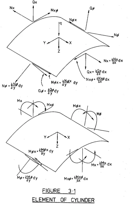
In a cylinder buckled into a true Yoshimura pattern and carrying some axial load each of the flat
facets will have some stress distribution. If we consider any two adjacent facets then any stress in one facet
perpendicular to the common fold will be matched by a similar stress in the adjacent facet. Thus a net radial force
would exist along the fold and this force could only be supported if the two facets were considered collectively as an extremely wide flanged beam in bending. Clearly, the structure could not support a substantial load in this manner so we can conclude that the stress in the facets perpendicular to the folds is negligible.
Obviously, if there is very small stress in the facets perpendicular to the folds then the load must be carried by stresses parallel to the folds. Some distance away from the fold these stresses would be relieved due to the flexibility of the shell. Thus the load is
carried principally along the folds and the structure can be considered as a space frame with slender members located along these folds (figure 2.2). The members would be wide flanged angles effectively pin-jointed with the load
FIGURE 2.2
SPACE FRAME MODEL
40. The geometry of the space frame is illustrated in figure 2.3 and from this geometry the following relations can be derived.
fiS 211 2.1
Axial length of facet (DE)
Axial deflection (unloaded)
Li 2(1-cOs(A/2)r
= -- 2.2 e.L2 (l+cos(A/2)
L2 Li 2 (l- cos(S/2)r = - L211 - (77E7) (l+cos(0/2))
2.3
The angle (Q) between adjacent facets along the diagonal can be shown to be
= 2.cos-1
Isin(R2)
Li N.COSt0/4)
7717'
2.4
From a consideration of axial equilibrium we can calculate the force in the diagonal members.
Li N2
P 1 4' (77E2
f
= 2.11
Ll 1 2
(l-cos( 2)
1 (2.12' (1+cos(0/2) And from radial equilibrium at a node we obtain.
- P
2 _ P1 2
1
2.6 Lo(l+cos(4/2)) (e) + i
tl
Thus for a given axial load on the cylinder
(P) the load in the diagonal member (P1) is of the same sign (both compressive in a buckling situation) while the
FIGURE 2.3
SPACE FRAME REPRESENTATION OF
YOSHIMURA PATTERN
42 load in the tangential member. is opposite in sign. Since the space frame has compression members these may in turn collapse through buckling. Suppose AC (figure 2.3) is to collapse through buckling then all the other members
remain somewhat in their original -positions but AC vanishes and in its place there is a new member FE. The angle
between the facets HAD and ABC becomes 180 0 so that this member also vanishes and we are left with another form of Yoshimura pnttern with larger facets ( a second buckling mode ). The members HF and HB are compressive members and
both can be shown to support the same load and both have the same angle between the facets. The tensile member is
F. Figure 2.4 shows a series of paper models. On the left is the conventional Yoshimura pattern with K=16. The second model is the corresponding second buckling mode assuming the entire cylinder collapses into this
shape. Obviously the compression members in this second mode can buckle but since both carry the same load the
long member will collapse first. The resulting buckled shape is similar to the first form but with half as many facets. The procedure can be repeated until complete collapse has been achieved. In this case N=2 which is flat because L1=2.L2.
4 3 .
P
ROGR
ESSIVE
C
OL LA
P
SE
0
0
0
2
Cr
Q_
a_
44. Secondly, there is a rotation of one end of the cylinder relative to the other. In the case of the second and sixth models in figure 2.4, this rotation is clockwise when viewed from on top.
In general, the second mode described here is not observed when testing cylinders in axial compression. Ifowever some evidence of its forming does exist. 7,sslinger and Geier (ref. 13) report that in testing very short
cylinders with the ends free to rotate a pattern was obtained of this forth (their Kreutzberg pattern). In
heavily deforming cylinders it is common to see the diagonal tension member between two facets. In figure 2.5 two such diagonals are evident in a shell made from melanex.
Clearly, the shell has been restrained from overall rotation so that a clockwise rotation in one section of the shell must be balanced by a corresponding anticlockwise rotation
in another. To test this principle further, several models of the YoshimUra pattern were made from melanex
FIGURE 2.5
BUCKLED MELANEX CYLINDER
WITH DIAGONALLY ORIENTED FACETS
46.
FIGURE 2 - 6
47. So fax this discussion has centered about
the collapse of structures which are true Yoshimura patterns. It is possible to consider a cylinder as a Yoshimura Pattern with a very large number of facets and a corresponding
large number of links in the space frame, each with a very short length. The collapse of these links could continue until we have the pattern that is so readily recognised. Unfortunately, boundary conditions on the cylinder do not permit such an idealised picture. The ends of the cylinder are usually restrained to be
approximately circular and some transition is necessary between the Yoshimura pattern that may develop in the centre and the circular ends. Two posfAbilities for this transition are shown in figure 2.7, both of which can be seen in Practical situations.
On the left of figure 2.7 is shown a paper model which has been folded so that there are four lobes
in the buckled pattern at the centre of the tube, with a transition to eight, sixteen and thirty-two. This type of pattern is often seen in cylinders that have been
substantially compressed after buckling has been first observed.
The model on the right of figure 2.7 illustrates a condition that occurs with somewhat less
compression though still substantially more than is required to buckle the cylinder. Yhe transition here is directly
4 8
49.
flattening of the small facets near the end of the large facets. Thus the small facets would be more uusceptable to collapse in this area. Also, in this free form model, the ends are not flat. It is actually sitting on four points equally spaced between the apexes of the larger lobes -. The corresponding increase in load in these areas would promote collapse of the small facets between the larger ones. Thus it is possible to infer that once the buckle Pattern has been formed it can grow to cover the entire cylinder.
The discussion to this point has been concerned with Yoshimura patterns spread over the entire cylinder and the simultaneous collapse of a number of column members in the resulting space frame. Obviously, the loading on the cylinder would not be completely uniform and one member would collapse before the remainder. Should this collapse be inelastic then the dimple so formed would remain fixed in position and the remaining compression members would progressively collapse away from that
location. Thus the buckle pattern could be seen to grow from an initial dimple. In the case of an elastic collapse of the compression member the dimple pattern can move
50.
For this reason a cylinder with a buckle pattern of, say 16 lobes would not collapse directly to a Pattern of 8 lobes but would collapse progressively through
15,14,13 etc. AlsO, a buckle pattern with N lobes in it would in general require less effort to collapse the diagonal compression member than to extend the buckle Pattern over the rest of the surface. Thus once a column member has been elastically collapsed a buckle pattern generally forms in the centre of the cylinder which has a length such that there is only one diagonal compression member. This type of pattern is illustrated by the very familiar model shown on the left of figure 2.8 (paper model) and in figure 2.9 (melanex cylinder with N=12). Esslinger and Geier term this type of buckle pattern a two tier pattern. In fact it has a length corresponding to just one compression member (and two tension members). Since we are concerned with the collapse of the compression member it would seem to be preferable to call this a one tier pattern. Their interpretation of a one tier pattern is actually a pattern where the buckling interferes with the fixed boundary, i.e. it is a pattern controlled by the boundary (see figure 2.10).
If the collapse of the diagonal compression member is considered in this model then the situation shown
on the right of figure 2.8 can be envisaged. Here a
51.
5 2 .
CT)
.
(N
3
cD
c
zsJ
LU
54.
by the tension member would be quickly brought together. If the collapse is elastic then the height difference would be evened out and a similar pattern formed with. one less lobe. However, should the cylinder be relatively short then on bringing the two corners together, the buckle pattern would interfere with the end boundary and be somewhat inelastic. The result would be that the pattern Would spiral around the cylinder; this situation is also often seen in shortish cylinders. Figures.
2.11 and 2.12 show buCkle patterns from advanced stages of collapse. In figure 2.11 (N=6) an extra facet has formed adjacent to the main buckle pattern which is the first stage of spreading of the pattern. In figure 2.12
(a very advanced stage of collapse) the buckle pattern is spiralling around the cylinder. There are also smaller facets present at the ends which are approximately half the size of the facets in the main body of the pattern.
Obviously, in considering true Yoshimura patterns and these paper models, the buckled shape is a stable configuration and one has to consider load reversal rather than unloading. The major difference between real cylinders and the models in this case is probably due to the small amount of bending rigidity at the corners.
In compressing a Yoshimura pattern it has
been demonstrated that there are diagonal compression
55.
FIGURE 2.11
(NJ
CD
LL
57.
load the diagonals become tension members and the tangential members are in compression. Thus the tangential membercan collapse as a column in buckling and the situation shown in figure 2.13 can arise (here shown as a Imre Yoshimura pattern). The sequence of models in this
photograph are T=8, second buckling mode, N=4 and a model representing the collapse of the tangential members. This last model has been folded to form a regular octagonal prism (for clarity) but obviously, it would in fact revert directly to a cylinder. In an actual cylinder the bending rigidity of the shell could force an intermediate pattern
into the shell with a higher number of lobes.
Now that the buckling behaviour of an
axially compressed cylinder has been explained qualitatively by reference to a space frame it remains to quantitatively
estimate the buckling loads of the space frame and hence the cylinder. However, the collapse of a diagonal member is not that of a simple Euler column. When the member AC
(in figure 2.14) starts to buckle then the diagonal
member FE begins to form. Although FB eventually becomes a tension member when the second mode is achieved, at the start of transverse deformation in AC there is a compressive force in FN. Thus it seems that a reasonable model for
the collapse of the Yoshimura buckle pattern is to
z
:4*
t;t
1
;t;t
Y OS H I MU RA
0
_J
59.
DEFORMED POSITION OF AC
FIGURE 2.14
60. Some justification for including the member FY as a spring can be oualitatively obtained by building
two identical paper Yoshimura models. In one some of the facets can be removed leaving a strip along each of the folds only. In the second model the member FW can also be left. Observation shows that the second model will support a substantially greater load than the first and sometimes the additional members will buckle.
During collapse of the member AC both points
A
and C move radially inwards while points F and B move outwards. In fact there appears to be very.little of this movement before the collapse load has been reached so thatthe purpose of investigating the collapse of AC, the relative movement of the corners can be ignored. However, when an axial load is supported by the cylinder without bucl.cling, the column members AF,AC and BC shorten and the tension members Al) and IC stretch. This change in
geometry has been taken into account in the following theory.
From figure 2.14 the following geometrical relations are obtained.
=
AP
2 AB2
2(1+cos(A/2) 2.7
AB OA
2.sin06/2)
ON _ 10.cosky4) 2.9
2.sin( 2)
„
II
AF2 + 2.An2 - 8.Al2.11- - .sin(P4)
-_
2
L22 4. (
31,1)
1 -- 2.12
P
2 , (1+cos(4/2))f4) + 4
1 -P
1 (2.6)
= f0A - + (or-TT) 2 - 2.0A.(0Y-17).cos() 4
T
= {0A2 +
a
- 2.011.172
- 2.0A.(0T::-Mr).cos( 4
N 1-
= ifAF2 + 2.AD2 - 8.AB.Tql.sinG4 O/42
61.
2.10
= 'AIL2 ( 31,1 )
71.
2.11(unloaded condition)
Thus the strain in 77 is
Consequently, the
restraining force
on thecentre of the
column is.
+ 2.AB2 - 8.AB.ITN.sin(ig/4) - P3 = 2 .E. W. T.
L22 I. (31,1) 2
- 1
2.13
Also
AP
= (1 +
P1
).K 2.14
2.T.E.W
AT = L1.(1 + 2.T.E.W P2 ) 2.15
and since
then
Substituting in the above, we have; - 62.
-8.L
1' MN..W.T.sin(04) P
3
_
I
1
.
2
) 2{1,2
+ (.4=) I1 2 2'L13
PI iC (l+cos05/2))136
+ 2.17
2 31, .1 2
IL
2 + (-
2
-±) iThe angle 1 between the restraining form and the column
is given by.
2 3. L12
4
2.18
Kil
23.L1
2 ( 7--)
Having determined the transverse restraining force
we can isolate the member AC and treat it as a buckling
pin ended column as illustrated in figure 2.15. At any
point "X" in the column the moment is given by.
= P1 (Y4W.cos(0/2))- P 3 .sin1.cos(9/2).(K/2-X)
= E.I.4
4
2.19T.O.cos2 (0/2)
and I
6
Thus Y = + C
2.cos(J.X) - 0.cos(9/2)
+ .-7.-8in,i.cos(0/2).(K/2-X) 2.20
rl
'1
where J2 =_
The constants of integration C i and C 2 are found
from the boundary conditions which are zero slope at the
P3 sin/
63.
P3
sin
I cos 2130n1
FIGURE 2.15
P
3. sinl. cos (A/2) 64. Thus
P
1'J
2.21 p 3 .siny.cos(A/2).sin(J.K/2) iw.cos(9/2)
P 1. J and C
2 cos(J.K/2) nt the centre,
=MN
P l .K
= 0 2 - 0.cos(0/2) + w,aw-sinl.cos(A/2) --- e•, r 2.23 Substituting for C 2 and P 3 we obtain,
[ 8.1,1.E.W.T.sin(04).sinIpcos(0/2) MN 11 '
+ ( 31, 1) 2 (K/2 -tan(J.K/2)/J) ..1
P1{L22
--2 r
+
3.1,1 2
I
L2 2 - -2- - - Of. cos (A/2){ 1
• cos(J.K/2)
Now, as the critical load of the column is approached the central deflection grows very large and we have in
the limit that,
8. L 1'
E. W. T. sin 04/4) . sinl. cos (0/2)
1 +
3.L1 P
IL
22
+=
0 2.25Solution of equation 2.25 leads to an evaluation of the compressive load carried by a diagonal member in the Yoshimura pattern at the point of collapse. The total load sup-ported by the structure is readily famnd since,
2.22
21, 3
sinl.cos(G/2)K2- +cos tan(*)
{
1-(2L12) 2 R:=1
= 2.N.P
1 2 I,
1) 1 + ( 7717
2.26
65.
The solution is multivalued. Figure 2.16 is a -plot of the value of this function for changing load (Pi or P). It can be seen that there is a root for no
- axial load. This root corresponds to a rigid body translation of the colizAn member. The next root is the solution
dsired while hit-her roots relate to higher buckling modes (of the column only). Thus to solve equation 2.25 by a trial and error method it is necessary to guess an initial value which - is high enough to prevent the solution converging on zero. It must also be low enough that the sclution will not converge to a higher mode. The general shape of this curve also highlights another problem with tle solution. If, for example, we were to assume a
diagonal member load of
7
Newtons for this cylinder and apply the Yewton-Raphson convergence criterion then the :olution would follow the .dotted line shown. The next guess would be about 151 Newtons and the solution would converge to some higher buckling mode. To overcome this problem it is necessary to apply a convergence factor(lass than unity) to the Newton-Raphson technique to ensure convergence to the correct value. This solution.
was -performed on a Digital PDP8 computer using the language FOCAI. A listing of the programme together with typical
output is given in Appendix G. As well as giving the
C:) 66. ..-.. o E z EE C71 0 0 CD cn C 1 1 e-- Q_ 0 0 ,..t z 11 II II II _ Z UJ ›- c.) O- rr) 0 0 0 —Jo <c)- 5 -<c`i LLI CO LU (\I Z 0 -(7) LU c• 0 C.)
FIGU RE
2. 16
67. properties of the first buckling mode(normal Yoshi]lura
Pattern) an:i . the second node '(pattern with - inclined tension members).
The expression for calculating the critical load Can be non-dir-lensionalised by using the following ratios,
2.27
2.28
2.29
2.30 22
2
L i
_ w Y and
Kence,
4 1+ qx.) 2 ) T3.4. 16.4).12 .si 2 (S/ ) n
4
A?
•
2.tanf4 612
74103 s in 2
)1
f
74ar3 si::(e4)
.
(i+A
In developing the theory to this point the author had become aware that a cylinder would have several buckling loads of differing values. Thus a load deflection curve would not have one peak ( as Von Karman and Tsien proposed ) but have several corresponding to the collapse of each mode. Within a couple of weeks of the author's
realisation of this point Esslinger and Geir's book (ref.13) appeared on the shelves of the University of Tasmania
68. library. On page 105 of this book is a gra -)h re3)roftuced here as figure 2.17 which shows these multiple Teaks
obtained ex)erimentally. This is the only reference that the author has found to show this -0roperty. All others have indicated a curve of the Von 7:arman and Tsien type. It aTnears to be a serious shortcoming in the published data which has at last been rectified.
It was decided to use the data from figure 2.17 to test the validity of the present theory. The only missing information was an estimate of the aspect ratio of the facets. To obtain thin; ratio several cylinders were manufactured from mslanex with various combinations of radius, thickness and length. It was found that with
these cylinders the aspect ratio (2/L 1 ) wa about 0.7 except where the iia.ern was seen to interfere with the • end of the cylinder. The other unknown variable in the
equation was the width of the flange of the angle member (W). This width was manipulated until for Y=15 (the first
C:)
0
c)
c)
c)
c)
c•
c)
(N) d OV01 1VIXV
6
9.
( RE FERE NCE 13)
E=
G Pa R= 100
m m
9
UJ
0
V)
FIGU RE 2.1 7
_J
X
T = 0 .19mm , L =100mm .
LOAD- SHORTENING
TABLT3 2 . 1
COMPARISON OF CALCULATED AND MEASURED POST-BUCKLING CRITICAL LOADS
R = 100mm. T = 0.19mm. W/T = 21
Number of
Critical Loads
Lobes Calculated Measured
(Esslinger and Geier) N
15 278 275
111 254 260
13 236 235
12 218 215
11 200 200
10 181 185
71.
The variation in critical load with number of lobes is plotted as figure 2.18 for an extended range of values of IT. The interesting point about this graph
is that there is a maximum with 38 facets of 518r. -53sslinger and Geier's cylinder buckled at a load of approximately
520Y. It is also interesting to note that by using high speed photography Almroth,Holmes and Brush (ref .14)
observed an initial buckle pattern with facets about half the size of the final pattern. Perhaps these smaller dimples correspond to the peak of the curve in figure 2.18 which corresponds to just over twice the number of lobes finally obtained.
Tlen a short cylinder is loaded in axial compression, then it is impossible to maintain the same aspect ratio as in a freely formed pa%tern. Firstly the buckles start to interfere with the ends and it is found' that the pattern spirals around the cylinder. It tends to break down completely over a considerable section until a different kind of Pattern evolves - Esslinger and Geir's one tier pattern. This type of pattern can not be properly represented by the simple space frame model presented
here. However, if the length of the facet (L 2 ) is limited to half the length of the cylinder and the preceding theory used to predict buckling loads, then an indication of the behaviour of the cylinder, is obtained. The two
o
o
o
o
o
o
o
o
o
o
to
Ln
....t
cn
cv
(SNO1M3N)
OV01 1V311183
7 2 .
c
o
n
YOSHIMU RA
73. of this curve for a 100mm. long cylinder with theprincipal buckling curve for the cylinder occurs at about the Position that the buckling pattern becomes irregular. Further
co)ression beyond this point appears to create a combination of buckling modes, one of which is approxiated by the
short cylinder branch and the other by the aspect ratio of 0.7. ,Then all the compression members with this higher aspect ratio are buckled e are left with the regular
buckle pattern that Esslinger and Geier call the one tier pattern.
Seeing that the collapse loads for Esslinger and Geier's cylinder have been satisfactorily calculated by this method it remains to estimate the corresponding deflections and complete a load deformation
graPh-Urfortunately, the calculation of deflection is not as ..,iatiPfactory because the geometry is not that of a simple Yoshirdura pattern. Apparently the bending rigidity of the
shell restricts the pattern from forming completely with the result that the actual shell is a little longer than would be predicted by the simple Yoshimurd geometry.
7 4 .
DEFO RMATION
0THEO RETICAL
Co
0
0
0
0
0
0
0
C:)
0
Co
Co
(r)
L.r)
■
4
cn
(SNO1M3N) OV01
75.
remainder of the length. Using this model meant that at each node there were -t;:o tangential members and two diagonal conjfession tibers instead of the four in the complete
pattern. Thus the force in the tangential member was half that -::reviously calculcited. The axial deflection was
estimated from the following expression.
- H (L - L2)(1 + P ) 2.32
2 R.T.E (P negative in compression)
This expression is linear and is represented in figure 2.19 by a straight line for each =de shape. The nomenclature ( 2,15 for example) is that adopted by
1]sslin,ger and Geier. It refers to a mode shape that has a Yoshimura Pattern length corresponding to one diagonal member (2 tangential members) and 1'3 lobes around the
circumference. Calculated deflections at collapse are within about 15 of the measured values.
One would expect that in loading the cylinder in a rigid testing machine a load deformation curve would reach a Dea'_c and irmaediately drop without increasing the axial deformation. Thus in considering the collapse according to figure 2.19 it would appear that the collapse would Progress through every mode shape after the Peak has been reached. The concept of a rigid machine applies only to the cylinder as a whole. We have
76. remainder of the cylinder as a somewhat flexible machine.
Thus the combination of cylinder and machine stiffnesses would produce a load release characteristic of the form represented by the dotted line in figure 2.19. In this cylinder it was known that the first post-buckling mode ha 15 lobes. Allowing for the fact that the deflections are aver-estimated as explained earlier, it is reasonable to expect a pattern of about 15 lobes from this diagram. The dotted line indicates the combined machine and cylinder characteristic necessary to achieve 15 lobes in the buckled shape according to this load deformation diagram.
Changing the length of the cylinder has nO effect on the critical loads since these are only dependent on the local buckling of the diagonal strut at the centre of the cylinder. However, increasing the overall length of the cylinder increases the length of the section that is not collasing. This portion is still deforming so that the buckle pattern has a smaller overall relative effect on the deformation. Figure 2.20 is a load deformation diagram for a cylinder of similar proportions to that used it deriving figure 2.19 except that the length has
been ouadrunled to 400 mm. By assuming the same cylinder-machine stiffness as in the previous case ( the dotted line ) a post-buckled shape with 10 lobes would be anticipated. However the extra length of the cylinder would mean that the combined machine-c7;lihder stiffness would probably be considerably less than previously
o
D
o
o
o
oo
o
o
o
co
L.r)
•4
el
cv
(SNOI.M9N) OV01 1V01112d0
0 •
0
_J
THEORET ICAL
77.
DE FL EC TION