International Journal of Innovative Technology and Exploring Engineering (IJITEE) ISSN: 2278-3075, Volume-8, Issue- 6S4, April 2019
Abstract—The network delay and power consumptions are the two main factors governing the efficiency of wireless sensor networks. In this paper, our goal is to minimize the delay and maximize the lifespan of event-based wireless sensor networks in which activities occur infrequently.In such architectures, most of the power is fed on when the radios are on, ready for a packet to arrive.Sleep–wake scheduling is a highly efficient mechanism to prolong the lifetime of these power-constrained wireless sensor networks. However, sleep–wake scheduling could provide result with considerable delays. This research attempts to limit these delays by developing “anycast” based packet forwarding schemes that places each node opportunistically forwards a packet to the first neighboring node which wakes up amongst more than one candidate nodes.In this paper, we propose to optimize the any-cast forwarding schemes by minimizing the anticipated packet-delivery delays from the sensor nodes to the sink node. Based on this analysis, we then provide a solution to the joint control problem of how to optimally manage the architecture parameters of the sleep–wake scheduling protocol and the any-cast packet-forwarding protocol to maximize the network lifetime, with reference to a constraint on the expected end-to-end packet-arriving delay.
1. INTRODUCTION:
Recent advances in wireless sensor networks have resulted in a functionality that remotely detects the environment and its activities. These aredeployed in remote or hostile areas.
ANYCAST FORWARDING AN,
Hence, it is observed that such network Functionality not adaptable for long period. Therefore, extending network lifetime and ensuring efficient power consumption are the key issues in the deployment of wireless sensor networks. In this paper, our focus is on event-driven asynchronous sensor networks with low bandwidth rates, whereevents willtakes place in rare situations.The power dissipation for sensing activities is typically steady and cannot be controlled. Hence, the energy required to maintain the communication system active (for listening to the medium and for manage packets), is the dominant factor for power consumption, which can be controlled for improving the network lifetime. Thus, sleep–wake up scheduling mechanism becomes an efficient mechanism to lengthen the life-span of resource-constrained wireless sensor networks. When there are no
Revised Manuscript Received on April 12, 2019.
Girish.R.Deshpande,Assistant professor, Dept. of CSE, GIT, Belgaum-590008. India.
Shrinivas.R.Dhotre,Assistant professor, Dept. of CSE, GIT, Belgaum-590008. India
Parutagouda.S.Khangoudar,Assistant professor, Dept. of CSE, GIT, Belgaum-590008. India
Sudhindra.K.Madi,Assistant professor, Dept. of ISE, GIT, Belgaum-590008. India
Mohammad AsifRaibag, Assistant professor, Dept. of CSE, PACEC, MANGLORE. Karnataka, India
activities, i-Motes will be put in sleeping mode to reduce the power consumption of the network.
SLEEP WAKE-UP SCHEDULINGPOLICIES
In this model, there are three manipulating factors that affect the network lifespan and the end-to-end delaycaused due to: wake-up rates, forwarding sets and priority.
1. Wake-Up Rates: Sleep– wake depends on the wakeup rate of the individual each node awakens. If the waking durability increases the expected hop-hop time duration will decrease. So it causes delay on entire end to end routing paths through the intermediate nodes. However Due to higher wake-up rate it causes bad impact on energy consumption and life span of the network.
2. Forwarding Sets: It is the collection of sensor nodes, from which we are choosing particular node to transfer a data. In this context, the set should contain nodes that can route data to the sink node in short duration. However end-end delay performance depend-ends on performance parameter of all the nodes which are identified in forwarding set.
2. LITERATURE REVIEW:
2.1 SLEEP–WAKE SCHEDULING:
Sleep-wake scheduling is an advantageous mechanism to enhance the life-span of energy-conserved sensor networks. However, sleep–wake scheduling may want to result in large delays because a transmitting node needs to wait for its next node to wake up. An interesting idea arises to minimize delay by introducing any-cast based data transmitting scheme, where each transmitting node first alerts and communicate to first neighboring node that wake ups among the multiple nodes in the topology.
3. PROBLEM ANALYSIS:
3.1 PROBLEM DEFINITATION:
In this work, we are addressing following parameters to improve the network efficiency.
1. First we are trying to find out how to minimize the delay problem, In this context, for given wake up rate of motes how to optimally implement any-cast forwarding mechanism to reduce end-to-end delay from all nodes to the destination node. We are introducing spatially distributed solution with less complexity.
2. We then find a solution for a life-time enhancement issue. There is hard constraint on the excepted delay between initial node to final node. We are trying to
Delay and Lifetime Issues for Wireless Sensor
Networks
achieve increasing life-span by combing wake-up rates and any-cast forwarding data transmission scheme. We are demonstrating how to apply solution for building network architecture with less delay and maximum lifetime.
3.2 EXISTING SYSTEM:
Latest trends in wireless sensor networks have capability of sensing different environmental conditions. These systems are most suitable for deploying in various phenomenons like military scenarios and hostile fields as well as in detecting various problems. But these networks are heavily affected by various hard constraints for life-time and energy consumption. Increasing life time through making efficient energy consumption is a biggest challenge in wireless sensor networks.
As it is mentioned in the literature reviews any-cast forwarding mechanism is the feasible solution to minimize the delay of event detections. In conventional system every node has been assigned to fixed next node in the neighborhood, and it waits for the next node to restate as active state for transmission.
DISADVANTAGE:
In existing frameworks the greater part of the vitality is devoured when the radios are on, trusting that a parcel will arrive.
In remote sensor systems have brought about an extraordinary capacity to remotely detect the earth. These frameworks are frequently conveyed in remote or difficult to achieve hostile areas.
Very difficult to that such systems work unattended for long terms. So broadening system life time through the effective utilization of vitality has been a key issue in the advancement of remote sensor systems.
3.3 PROPOSED SYSTEM:
In this research, mainly focusing on event based asynchronous sensor networks with consumption of less bandwidth, where event happens rarely. This is important aspect of networks is used to observe environmental conditions, military activities.
In this technique, by using any-cast forwarding mechanism, each node contains multiple neighboring nodes which are registered in the forwarding set. The first node attempts to route the data to the other node that alerts remaining nodes by using wakeup scheduling algorithm. It is clearly observed that as compared to basic scheme which reduces delay in between initial node to final node.
For example, just assume there are n nodes in the given forwarding set, every candidate node alerts and wake up independently according to the Poisson process with the same date rate, and then anycast mechanism can reduce the end to end delay.
ADVANTAGES
Limiting the maximum time consumption and expanding the lifespan of event-based remote sensor systems for which event happens indefinitely.
This idea is a successful for achieving maximum lifetime for the resource constrained wireless sensor networks.
It’s one of the good ideas for achieving data delivery rate from source to destination.
To reduce these time difference in between every node by creating "any-cast" based data transmission techniques.
4. MODULES
4.1 MODULES DESCRIPTION 1. Sources
2. Maximizing Lifetime 3. Minimizing Delay 4. Any cast Forwarding 5. Sleep-wake Scheduling 6. Sink
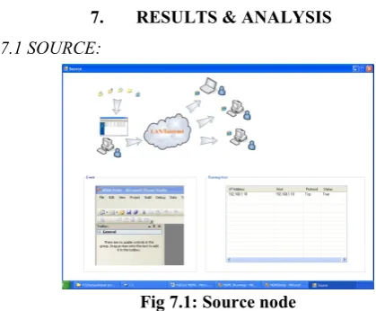
4.1.1 Sources:
The fundamental objective of the single source node communicates and report all the events and system changes to the sink node. In such frameworks, there are four primary sources of energy consumptions: Energy required for maintaining control messages over the different nodes, energy cost for keep sensor nodes on, energy required to message transmission and reception process. Finally energy required to maintain security measures in the network. 4.1.2. Any Cast Forwarding:
This module is more feasible for minimizing delay by applying any-cast based forwarding data transmission mechanism, here each source node selects neighboring node, that alerts multiple nodes to become active which are present in forwarding set. The main goal of this module is reducing excepected data delivery delay from source node to destination node. This scheme clearly reduces the expected delay in between successive nodes.
4.1.3. Sleep-Wake Scheduling:
Sleep–wake-up scheduling mechanism becomes an efficient mechanism to lengthen the life-span of resource-constrained wireless sensor networks. The power dissipation for sense the event is usually unchanged and it’s very difficult to monitor. Hence, energy cost for maintaining the active state of the sensor node is the main source for energy consumption, which can be reduced to strengthen network lifespan.
International Journal of Innovative Technology and Exploring Engineering (IJITEE) ISSN: 2278-3075, Volume-8, Issue- 6S4, April 2019
4.1.4. Sink:
Sink is a base station, this is a last stage, and the occasions are gotten from various remote sensor hub by this stage. To streamline the any cast sending plans for limiting the normal parcel conveyance delays from the sensor hubs to the sink.
When source node detects any events, the node collects all the information and marshaled into a single request message. The request message is sent via the communication channel by using multi-hop routing technique. Every node has at-least one path to the sink node through intermediate nodes.
5. SYSTEM ARCHITECTURE AND DESIGN:
5.1 SYSTEM ARCHITECTURE
The design of software framework is the estimated plan that characterizes the structure as well as conduct of a design process. A software system design is a formal depiction of a framework, collected all the information in a way that it supports reasoning about structural parameters of the framework. It characterizes the system architecture modules and it, gives an idea about how products can be designed, and how system is designed, that collectively work together to design the overall software framework. This overall process helps us to scrutinize in a way that it covers all functional and non-functional requirements of customer needs.The main designof a framework, encapsulated in its individual modules , their connections to one another and its surroundings, and the standards adapted for design and development process.
5.1 System architecture diagram 5.2 ACTIVITY DIAGRAM
Activity charts explains about execution of process and their different possibilities etc.Activity charts are like a state charts because every action is the condition of execution of some mathematical expression.The activity charts portray the condition of exercises by demonstrating the list of tasks performed at every stage. Activity charts can demonstrate tasks that are concurrent or simultaneous. Activity charts should be used identified with other showing systems, for instance, coordinated effort outline and state chart. The benefits of using activity chart are to visualize work behind the framework design phase. And these are also useful for understanding functions of individual actors it defines what steps we have carry out when those functions performed by user. Describing a complicated sequential algorithm and modeling applications with parallel processes.
Fig 5.2 shows Activity Diagram
6. IMPLEMENTATION
Framework Implementation is the phase in the undertaking where the hypothetical structure is transformed into a working framework. The most basic stage is accomplishing a fruitful framework and in giving certainty on the new framework for the client that it will work proficiently and adequately.The current framework was long time process. The proposed framework was created under platform C#.NET. The current framework caused long time transmission process however the framework grew now has a generally amazing easy to use more interactive graphical user interface, which has a menu-based interface, graphical interface for the end client.In the wake of coding and testing, the venture is to be introduced on the essential framework. The executable record is to be made and stacked in the framework. Again the code is tried in the introduced framework. Introducing the created code in framework as executable document is usage.
[image:3.595.305.515.477.650.2]7. RESULTS & ANALYSIS 7.1 SOURCE:
Fig 7.1: Source node
7.2 SINK:
7.2 sink node Digram
In the above diagram data is arrived to the destination. The entire delay caused by every node and we are plotting graph number of data packets vs delay caused by every node.
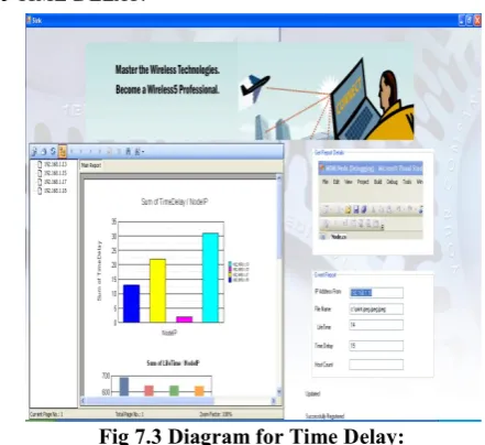
[image:4.595.54.275.249.451.2]7.3 TIME DELAY:
Fig 7.3 Diagram for Time Delay:
In the above diagram after transferring data from source to sink its showing delay happen for transmission. As compared to existing system there is massive improvement is achieved. In the above scenario we are calculating delay caused by individual node. It’s numerically represented as 15seconds.
[image:4.595.53.280.542.722.2]7.4 DETAILS:
Fig 7.4 Diagram for Details
In above diagram we are showing all the sensor nodes and delay caused by every node and also it’s clearly shows life time of all the sensor nodes. It’s very clear from above diagram the relationship in between delay and life time.
7.5 LIFETIME:
Fig7.5 diagram for life time graph
The above graph which is generated in our work, it shows maximum life time achieved by every sensor nodes after minimizing one-hop delay and end-to end delay. The graph is plotted node versus life time of respective sensor nodes. After reducing energy consumption there is lot of improvements with respect to network life time.
7.6 PERFORMANCE COMPARISON BETWEEN EXISTING AND PROPOSED SYSTEM:
Noof nodes
Exiting System
ProposedSyste m
Delay Energy Delay Energy 200 3.90 0.62 2.1 0.70 250 4.2 0.59 1.923 0.83 300 4.42 0.62 1.76 0.85 350 5.56 0.58 2.43 0.80 400 4.9 0.495 2.6 0.7 450 4.7 0.49 2.3 0.96 500 7.22 1.0 2.36 1.1
7.6Performance comparison b/wexisting and proposed system
The above table contains result comparison in between existing system and proposed system. As per the result analysis there is drastic improvements in performance metrics. We are considering two parameters i).Delay ii) Battery-Consumption (Energy).
As per existing system there is more consumption for every transmission even there is maximum delay in between source to destination but more energy consumption. We are considering group of sensor nodes. We are trying to observe delay versus energy consumption.
International Journal of Innovative Technology and Exploring Engineering (IJITEE) ISSN: 2278-3075, Volume-8, Issue- 6S4, April 2019
8. CONCLUSION
In this research, we addressing two main problems associated with sensor networks applications. First delay caused by every sensor node while transferring data from source node to base station. Second problem with maintaining maximum life time due to more energy consumption. The problem of delay is minimized by implementing any-cast forwarding scheme in the proposed system. By using Sleep-wake scheduling approach, it helps to reduce unnecessary wastage of energy, helps to maintaining stable life time. Our numerical results are carried out under different scenarios. Results are shows there is 40-50% improvement with existing system.
REFERNCES:
1. J. Kim, X. Lin, N. B. Shroff, and P. Sinha, “On maximizing
the lifetime of delay-sensitivewireless sensor networks with anycast,” in Proc. IEEE INFOCOM, Pheonix, AZ, Apr. 2008, pp. 807–815.
2. Y.-C. Tseng, C.-S. Hsu, and T.-Y. Hsieh, “Power-saving
protocols for IEEE 802.11-based multi-hop ad hoc networks,” Comput. Netw., vol. 43, pp. 317–337, Oct. 2003.
3. T. van Dam and K. Langendoen, “An adaptive
energy-efficient MAC protocol for wireless sensor networks,” in Proc. SenSys, Nov. 2003, pp. 171–180.
4. G. Lu, B. Krishnamachari, and C. S. Raghavendra, “An
adaptive energy-efficient and low-latency MAC for data gathering in wireless sensor networks,” in Proc. IPDPS, Apr. 2004, pp. 224–231.
5. J. Elson, L. Girod, and D. Estrin, “Fine-grained network time