International Journal of Innovative Technology and Exploring Engineering (IJITEE) ISSN: 2278-3075, Volume-8 Issue-9, July 2019
Capacity Analysis and Linear Detection in Massive
MIMO for 5G Wireless Systems
Haresh L. Judal, Kishor G. Maradia
Abstract: Multiple Input Multiple Output (MIMO) is an attractive air interface solution which is used in the 4th generation wireless networks to achieve higher data rate. With a very large antenna array in Massive MIMO the capacity will increase drastically. In this paper channel capacity comparison for MIMO using known Channel State Information (CSI) and unknown CSI has been carried out for a higher number of antennas at transmitter and receiver side. It has shown that at lower SNR known CSI will give better performance compared to unknown CSI. At higher SNR known CSI and unknown CSI will provide similar results. Capacity comparison has been evaluated with help of MATLAB for known CSI and unknown CSI from a small number of antennas to hundred of antennas. Also, the performance evaluated with MATLAB simulation of linear detectors zero-forcing (ZF) and maximum ratio combining (MRC) method for large number of antennas at Base station (BS) which are serving a small number of single antenna users. Performance is evaluated in terms of Symbol Error Rate (SER) for ZF and MRC, and results show that ZF will outperform MRC. It has also been analyzed that increasing the antennas at BS for a small number of users will also help to reduce SER.
Keywords: MIMO, ZF, MRC, BS, SER
I. INTRODUCTION
The Multiple-Input Multiple-Output (MIMO) has the potential to improve the capacity of wireless systems. MIMO communication system employs multiple antennas at the transmitter and the receiver side. MIMO systems offer additional degrees of diversity which can be used to combat multipath fading in a wireless channel.
Massive MIMO system is currently considered the most compelling technology for the 5G wireless networks, [1][9][10][12]. The Base station (BS) contains a large number of antenna elements in the order of hundreds or more which is simultaneously serving tens of mobile terminals (MTs) in Massive MIMO. Uncorrelated noise and multiuser interference effect can be made small due to coherently combining signals at BS antennas [2], [3], [11]. Hence network capacities can be unprecedently achieved. If the number of BS antennas grows larger than the random channel vectors between the BS and the users, become pairwise orthogonal [4]. With simple matched filter processing at the BS uncorrelated noise and intracell interference disappear completely if the infinite numbers of antennas can be taken at the BS. Massive-MIMO technology is a promising solution to meet a demand for higher data capacity in 5G Wireless Communication Networks. The increase in antennas at transmission and reception open a door for research in the theory of Communications.
Revised Manuscript Received on July 09, 2019
Haresh L. Judal
,
Ph.D. Scholar, E & C Engineering Department, Gujarat Technological University Ahmedabd, Gujarat, India.Kishor G. Maradia, Professor& Head, E& C Engineering Department, Government Engineering College, Gandhinagar Sector 28, Gujarat, India.
In this paper, simulation is done based on the expression for the capacity of the MIMO channel for known Channel State Information (CSI) and unknown CSI. It has also shown that using a higher number of antennas at transmitter and receiver provide a capacity gain in terms of bits/s/Hz. In this paper, the comparison has been made between maximum ratio combining (MRC) and zero-forcing (ZF) linear detectors in Massive MIMO environment.
In this paper Section II explains the MIMO architecture and the theory behind it. In Section III explanation is given for the capacity of MIMO for unknown CSI and known CSI. Massive MIMO is explained in Section IV. Section V explains linear detectors used in Massive MIMO. The results from simulation are presented in Section VI. A conclusion of the paper is given in Section VII.
Notations: The superscript (.)H indicates conjugate transpose; the squared Frobenius norm of H represented by
and IN is the N × N identity matrix.
II. MIMO SYSTEM MODEL
In a MIMO system data are transmitted with Nt transmitting
antenna arrays. The receiver is constructed with Nr antenna
arrays.
A spatial multiplexing MIMO system transmits different data symbols from each transmitter. The signals from each transmitter combine over the air and are received by multiple receiver antennas.
The MIMO model can be described as
y=Hx+n (1)
Where H is the channel matrix, x is the transmitted signal, y is the received signal and n is the noise.
III. THE CAPACITY OF A MIMO SYSTEM MIMO contains Nt transmitter antennas and Nr receiver
antennas. H contains Nr×Nt channel coefficients.
If the channel is unknown to the transmitter than the signals
are assumed to be independent and equal power is
transmitted from transmitter antennas. The capacity of the
MIMO for the unknown CSI at the transmitter is given by
C=log2det (INr+ (2)
Given that HHH=QλQH, then the capacity of MIMO can be
C=log2det (INr+ (3)
Using the identity of matrix
The rank of the channel matrix is r and (i=1, 2……..r) are the positive eigenvalues of .
In the absence of channel knowledge equal transmit energy allocated to each spatial data pipe.
Given a fixed total power =
Where, is the total power gain of the channels.
Consider a full rank MIMO channel with Nt=Nr=N so that
r=N. If = = (i,j=1……...N)and H is the orthogonal
matrix such that then resulting capacity
will be
C=Nlog2(1+ .
(5)
If elements of H satisfy such that =1⇒ =
then
Cmax=Nlog2(1+
(6)
Which is equal to the N times the capacity of SISO channel for unknown CSI.
For CSI known, power allocation strategy extracts the information regarding conditions of channels which are good and which are not, and accordingly power is allocated to the channels. In this way, the overall capacity of the system is maximized so that the spectral efficiency is improved. This strategy is also referred to as water filling algorithm in MIMO communications.
After applying SVD and further processing, the conventional MIMO system becomes similar to a collection of non-interfering SISO systems. SVD is helpful not only in decomposing the interfering paths into parallel non-interfering channels but also it helps to identify the quality of those parallel channels. Based on the quality of channels, the power is allocated such that maximum data rate can be achieved. The diagonal elements ∑ are the singular values of the channel matrix H which are the square roots of the eigenvalues. A number of non-zero diagonal elements of ∑ cannot exceed the rank of the channel matrix, H, as the number of non-zero eigenvalues is the rank of the matrix. Received signal at the receiver without preprocessing at the transmitter will be r=Hx +n. With preprocessing at transmitter transmitted signal will be HVx instead of Hx and Received signal, in this case, will be r=HVx+n.
Where H=U∑
r= U∑ Vx+n
r= U∑x+n (7)
At receiver with processing y=
y= (8)
y= ∑x+ n (9)
= i (10)
MIMO channels have been virtually decomposed as parallel SISO channels through the process of transformations at transmitter and receiver.
The capacity of the MIMO model is algebraic sum of the
capacities of all channels
C= (11)
Water filling algorithm can be applied with the following expression.
=
i (12)
C= (13)
Maximum capacity can be find using, [7][8]
C=
(14)
The channel which contains higher SNR will be given more power, and more power increases the sum of data rates in all subchannels. λi indicates the strength of the signal of MIMO subchannel. If λi is higher more power allocated to the same subchannel. is optimum power allocated to given subchannel.
The power given to each subchannel is calculated using,
[5][16].
Power allocated =
(15)
Where Pt is the power of the MIMO model and channel
matrix is represented by H.
By knowing channel statistics, the extra power is allocated at the transmitter side hence capacity can be increased according to the water filling algorithm.
IV. MASSIVE MIMO
Massive MIMO model is described where BS is equipped with arrays of M antennas that receive data from N single antenna users where M>>N.[17],[19],[20].
In the uplink the BS receives
y= x+n (16)
Where x=[ ,……… ]T is the vector of information symbols, is transmitted by the single antenna Nth terminal. The G is the channel matrix between M antennas at the BS and N users are G∈ . The p is the normalized SNR of each user and n is the vector of additive white Gaussian noise with zero mean and variance 1.
The sum channel capacity of the channel model described above is, [6][13][14][15]
(17)
V. LINEAR DETECTORS
International Journal of Innovative Technology and Exploring Engineering (IJITEE) ISSN: 2278-3075, Volume-8 Issue-9, July 2019
MRC and ZF detectors have been considered here. In this paper, we have simulated the SER for ZF and MRC only. Suboptimal low complexity Massive MIMO detection at BS combining is done using r=Ay.
For MRC: A=
(18)
For Zero Forcing: A=( )-1
(19)
From (16) and (18), the received vector for MRC is given by
r= x+n) (20)
It is assumed that users , , ……… are independent.
SINR for nth received element for MRC is given by
SINRMRC=
SINRMRC, n=
(21)
From (16) and (19), the received vector for ZF linear detector is
r = ( )-1 x+n) (22)
= + )-1 (23)
It will able to suppress Multiuser interference. SINR for ZF is given by
SINRZF, n=
(24)
VI. SIMULATION RESULTS
The results of the simulations are presented in this section. A comparison has been carried out with different size of arrays at transmitter and receiver side. At the end of this section comparison and analysis has been carried out for the linear detectors, ZF and MRC.
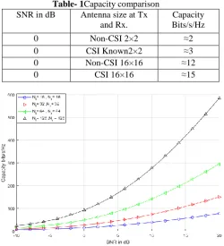
From Fig. 1 analysis has been carried out in Table- 1 for different size of antennas at transmitter and receiver side. It shows there is an improvement in the capacity if the size of the antenna has been increased. Due to water filling applied for known CSI it will give more capacity compared to unknown CSI for the same number of antenna combinations at transmitter and receiver side.
[image:3.595.310.559.48.230.2]From Fig. 2 analysis has been done in Table 2 for different number of combination of antennas at transmitter and receiver side for known channel state information. There is a huge improvement in the capacity in terms of Bits/s/Hz if the size of antennas has been increased from the 16×16 to 128×128.At 20 dB SNR, 16×16 will give 75 Bits/s/Hz while 128×128 antennas will give 600 Bits/s/Hz.
Fig. 1. Channel Capacity comparison of Non-CSI and known CSI for Nt=Nr=2, Nt=Nr=4, Nt=Nr=8, Nt=Nr=16
Table- 1Capacity comparison SNR in dB Antenna size at Tx
and Rx.
Capacity Bits/s/Hz
0 Non-CSI 2×2 ≈2
0 CSI Known2×2 ≈3
0 Non-CSI 16×16 ≈12
[image:3.595.309.560.272.548.2]0 CSI 16×16 ≈15
Fig.2. Channel Capacity comparison of known CSI for Nt=Nr=16, Nt=Nr=32, Nt=Nr=64, Nt=Nr=128 Table-2Capacity comparison for different size of
Antennas SNR in dB Antenna size at Tx
and Rx.
Capacity Bits/s/Hz
20 CSI 16×16 ≈75
20 CSI 32×32 ≈150
20 CSI 64×64 ≈300
Fig. 3. Channel Capacity comparison of Non-CSI and known CSI for Nt=Nr=16, Nt=Nr=32, Nt=Nr=64,
Nt=Nr=128.
From Fig. 3 it can be observed that as the antenna size increases for known CSI and non-CSI there is an improvement in the capacity in Bits/s/Hz. Further, it has been observed that at very low SNR known CSI will give better result compared to unknown CSI as it can be increased with the help of water filling model. At higher SNR known CSI and non-CSI will provide similar results for a higher number of antennas at transmitter and receiver side.
It has been observed from Fig. 4 that for a fixed number of transmitter antennas and if the size of the receiver antenna has been increased at receiver side then capacity improvement will be there.
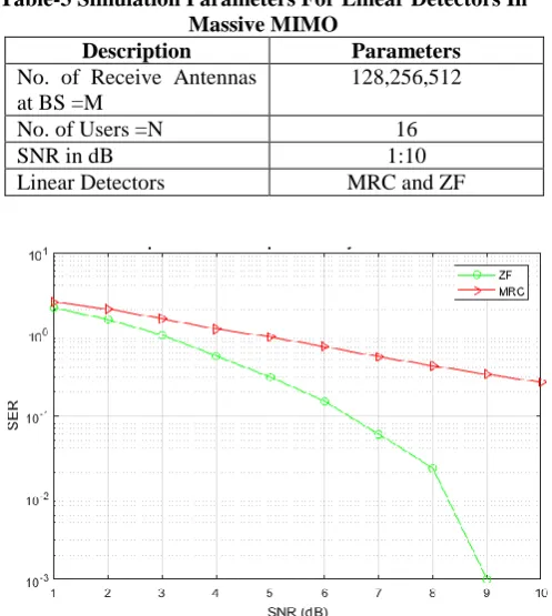
[image:4.595.309.558.57.335.2]Linear receivers perform well when the BS contains a large number of antenna elements at the BS and is serving tens of mobile terminals (MTs) which are the case of Massive MIMO. The system parameters that were used in simulations of linear detection, ZF and MRC for Massive MIMO are shown in Table 3. For the comparison of linear detectors like ZF and MRC, hundreds of base station antennas and small number of single antenna user terminals have been taken for simulation.
Fig. 4. Channel Capacity comparison with known CSI for Nt=16 and Nr=16, 32,64 and 128
Table-3Simulation Parameters For Linear Detectors In Massive MIMO
Description Parameters
No. of Receive Antennas at BS =M
128,256,512
No. of Users =N 16
SNR in dB 1:10
Linear Detectors MRC and ZF
Fig. 5.: SER Performance Comparison for M=128 Receive Antennas at Base station and N=16 Users for ZF
and MRC
As shown in result of Fig. 5, Massive MIMO using the ZF and MRC techniques was compared, and clearly, there is an improvement in terms of SER when using ZF compared to MRC. It has been observed that the MRC performs worst in terms of error rate performance.
[image:4.595.311.559.510.703.2]As per simulation result of Fig. 5 and Fig. 6 analysis has been carried out in table 4, and it shows that there is an improvement in the performance of SER when the number of antennas has been increased at BS from 128 to 256. Also, it has been shown that ZF will give good performance compared to MRC.
Fig. 6.: SER Performance Comparison for M=256 Receive Antennas at Base station and N=16 Users for ZF
[image:4.595.51.299.538.717.2]International Journal of Innovative Technology and Exploring Engineering (IJITEE) ISSN: 2278-3075, Volume-8 Issue-9, July 2019
Table 4 Simulation results of MRC and ZF Linear Detectors
SNR (dB)
M=128 Antennas at BS and N=16
M=256 Antennas at BS and N=16 SER of
MRC
SER of ZF
SER of MRC
SER of ZF
1 2.492 2.118 0.769 0.464
2 2.047 1.521 0.509 0.25
3 1.561 0.981 0.339 0.114
4 1.164 0.546 0.225 0.044
5 0.931 0.3 0.119 0.012
6 0.706 0.152 0.069 0.001
From Table 4 it has been observed that at 6 dB SNR for M=128 antennas and N=16 users MRC will give 0.706 SER while for same SNR for M=256 antennas and N=16 users SER will be 0.069. At 6 dB SNR for M=128 and N=16 users will provide a 0.152 SER while for M=256 and N=16 users SER will be only 0.001 in case of ZF linear detection.
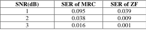
Fig. 7.: SER Performance Comparison for M=512 Receive Antennas at Base station and N=16 Users for ZF
and MRC
Table5 MRC and ZF Linear Detectors comparison for M=512 Antennas at BS and N=16 users
SNR(dB) SER of MRC SER of ZF
1 0.095 0.039
2 0.038 0.009
3 0.016 0.001
From Fig.7 and analysis as per table 5, for higher number of antennas like 512 antennas at BS for a small number of users then there is an improvement in the SER. It has been analyzed that at 1 dB SNR MRC will give a 0.095 SER while ZF will give a 0.039 SER.
VII. CONCLUSION
In this paper capacity comparison has been carried out for known CSI and unknown CSI in MIMO wireless communication model. We have compared capacity from a small number of antennas to hundreds of antennas at transmitter and receiver side. It was found that using higher number of antennas capacity improvement is possible for
known CSI and unknown CSI. Using water filling model we can increase the capacity at low SNR for known CSI. It was also observed that at higher SNR, known CSI and unknown CSI will give similar results for larger number of antennas.
In Massive MIMO systems MRC detector will give worst result compared to ZF. It was also concluded that increasing the antennas at the BS for small number of serving users then performance improvement is possible in terms of SER.
REFERENCES
1. F. Boccardi, R. W. Heath, A. Lozano, T. L. Marzetta, and P.Popovski:’Five disruptive technology directions for 5G’, IEEE Communications Magazine, vol. 52, no. 2, pp. 74–80, Feb. 2014. 2. T. L. Marzetta :’Noncooperative Cellular Wireless with Unlimited
Numbers of Base Station Antennas’, IEEE Transactions on Wireless Communications, vol. 9, no. 11, pp. 3590–3600, Nov. 2010. 3. F. Rusek, D. Persson, B. K. Lau, E. G. Larsson, T. L. Marzetta, O.
Edfors, and F. Tufvesson : ’Scaling Up MIMO: Opportunities and Challenges with Very Large Arrays’, IEEE Signal Processing Magazine, vol. 30, no. 1, pp. 40–60, Jan. 2013.
4. H. Q. Ngo, E. G. Larsson and T. L. Marzetta :’Energy and Spectral Efficiency of Very Large Multiuser MIMO Systems’ IEEE Transactions on Communications, vol. 61, no. 4, pp. 1436–1449, April 2013.
5. A. Vipin Kumar, Dr. Praveen Dhyani :’Channel Capacity Analysis of MIMO OFDM System Using Water Filling Algorithm under AWGN and Rayleigh Fading Channel’, American International Journal of Research in Science, Technology, Engineering & Mathematics, vol. 1, pp. 1436– 1449, Dec-Feb 2015-16.
6. M. Zourob and R. Rao :’On linear detector's spectral capacity for massive MIMO systems’, 2017 International Conference on Electrical and Computing Technologies and Applications (ICECTA), Ras Al Khaimah, 2017, pp. 1-5.
7. ArogyaswamiPaulraj, Rohit Nabar, and Dhananjay Gore. 2008.:‘Introduction to Space-Time Wireless Communications’ (1st ed. Cambridge University Press, New York, NY, USA).
8. M Cover, Thomas & A Thomas, Joy. (1990): ‘Elements of information theory’ (2nd ed. Wiley).
9. Y. Kishiyamaet al. :’Future Steps of LTE-A: Evolution towards Integration of Local Area and Wide Area Systems’, IEEE Wireless Commun., vol. 20, no. 1, Feb.2013, pp. 12–18.
10. T. Rappaport et al.,:’Millimeter Wave Mobile Communications for 5G Cellular: It Will Work!’, IEEE Access,vol. 1, 2013, pp. 335–49. 11.E. Dahlman, S. Parkvall, J. Skold, and P. Beming,’3GEvolution:
HSPAand LTE For Mobile Broadband’( 2ndedition. Elsevier, 2008) 12.Tan, Weiqiang& Huang, Wei & Yang, Xi & Shi, Zheng & Liu, Wen
& Fan, Lisheng.:’ Multiuser precoding scheme and achievable rate analysis for massive MIMO system’, EURASIP Journal on Wireless Communications and Networking. 2018.
13.J. Zhang, L. Dai, M. Matthaiou, C. Masouros and S. Jin, :’On the spectral efficiency of space-constrained massive MIMO with linear receivers’, 2016 IEEE International Conference on Communications (ICC), Kuala Lumpur, 2016, pp. 1-6.
14.H. Tataria, P. J. Smith, M. Matthaiou, H. Q. Ngo and P. A. Dmochowski, :’Revisiting MMSE Combining for Massive MIMO over Heterogeneous Propagation Channels’, 2018 IEEE International Conference on Communications (ICC), Kansas City, MO, 2018, pp. 1-7.
15.M. Shafi et al., ‘5G: A Tutorial Overview of Standards, Trials, Challenges, Deployment, and Practice’, in IEEE Journal on Selected Areas in Communications, vol. 35, no. 6, pp. 1201-1221, June 2017. 16.Remika N gangbam, R.Anandan, Chitralekha N gangbam.:‘
MIMO-OFDM based Cognitive Radio Networks Capacity analysis with Water Filling Techniques’, International Journal of Computer Science &Communication Networks, Vol 3(3),160-163. 17. A. Gupta and R. K. Jha,: ‘A Survey of 5G Network: Architecture
and Emerging Technologies’, in IEEE Access, vol. 3, pp. 1206-1232, 2015.
[image:5.595.51.294.571.622.2]Photo
19.C.-X. Wang et al.:’Cellular architecture and key technologies for 5G wireless communication networks’, IEEE Commun. Mag., vol. 52, no. 2, pp. 122-130, Feb. 2014.
20.P. Agyapong, M. Iwamura, D. Staehle, W. Kiess, A. Benjebbour.:’Design considerations for a 5G network architecture’, IEEE Commun. Mag., vol. 52, no. 11, pp. 65-75, Nov. 2014. 21.A. Osseiran et al.:’Scenarios for 5G mobile and wireless
communications: the vision of the METIS project’, in IEEE Communications Magazine, vol. 52, no. 5, pp. 26-35, May 2014.
AUTHORSPROFILE
Haresh L. Judal is currently working as an assistant professor at Government Engineering College Patan, Gujarat, India. He has completed his B.E. (Electronics and Communication Engineering) from the North Gujarat University. He has completed his M.E. from L. D. College of Engineering Gujarat University Ahmedabad. Currently he is working in the field of MIMO and OFDM.
Kishor G. Maradia has completed his B.E. (Electronics and Communication Engineering) from the Bhavnagar University in 1992 and M.E. (Electronics and Communication) with specialization in the field of communication systems from L. D. College of Engineering, Gujarat in year 2003. He has completed his Ph.D. from M. S. University Baroda. He is a life member of IETE, CSI, LAA and other professional societies. He is guiding research students in the field of MIMO, OFDM, Optical communication and wireless communication.
.