International Journal of Innovative Technology and Exploring Engineering (IJITEE) ISSN: 2278-3075, Volume-8 Issue-9, July 2019
Abstract— A feature model for the processing of digital is the estimated calculating at Nano metric scales. Accurate calculating is especially simulating for arithmetic designing of computer. This suggested project is contracts with the research and implementation of two new estimated 4-2 compressors for implementation in a multiplier. These implementations are depends on other characteristics of compression. Hence that inaccuracy in calculation as restrained by the rate of error and that called distance of normalized error can come across to figures of merits of implementation amount of transistors, delay and power consumption. Four various patterns for using the suggested estimated and evaluated for a Dadda multiplier wide ranging simulated outputs are given and the use of estimated multipliers to processing of image is given. The output displays that the given implementation achieved specified falls in the consuming of power, delay and count of transistors correlated to a specified implementation; in addition, two of the suggested multipliers implementation gives good abilities for multiplication of image to average NED and peak SNR (>50db) for the measured image examples.
Index Terms: Dadda multiplier, compressor, image processing, Inexact compressor, ADVS (Arithmetic Data Value Speculation),. HSPICE, signal to noise ratio (SNR), NED (Normalized Error Distance.)
I. INTRODUCTION
The most computer arithmetic applications are designed; those are operating with good precision and a good reliability of high degree. Hence, most applications i.e., in image processing can allow mistakes and impression in arithmetic calculation and useful results and still generate significant results. Precise and exact models and algorithms are not every time fit or for systematic use in the applications. The pattern of inaccurate arithmetic depends on calm fully inexact and complexity determined building parts when considering example systems of efficient-energy systems are designing. This system admits computation of non-specific to alter the process of the actual design of digital circuits by communicable asset of a reduce intricacy and amount with by chance a prospective growth in accomplishment and efficiency of power. To achieve the simple design, in-accurate calculation depends on this property, yet inexact circuits are working at high accomplishment and less consumption of power when correlated specified logic circuits.
Multiplication and additions are mostly used in arithmetic operations of computer; for approximate computing has compared those proposed several new matric and adders for
Revised Manuscript Received on July 05, 2019.
Sk.Anusha, Electronics and communication engineering, M.Tech
student, School of engineering and technology, Sri Padmavathi Mahila Viswavidyalayam. , Tirupathi, India.
M.Krupa Swaroopa Rani, Assistant Professor, Electronics and
communication engineering fromSchool of engineering and technology, Sri
Padmavathi Mahila Viswavidyalayam. , Tirupathi, India.
evaluating inexact and prospect address corresponding to uniformed figure of merit for assessment implementation for approximate calculating of every input to a circuit, for characterizing the error distance(ED) as the distance between the (1) and an flawed output. The normalized error distance (NED) and mean error distance (MED) is expected by considering the arranging effect of the normalization of multiple-bit address and multiple inputs. The Normalized Error Distance and the mean distance of errors are expected by considering the arranging effects of the normalized of multiple bit address and multiple inputs. The normalized error distance is approximately constant with size of performance and hence helpful accuracy estimation of exact implementation. The establishment between power and precision are also significantly calculated (1).
After all, the inexact implementation multiplies will be received lower attention. This multiplication will be idealized as the replicated sum of incomplete result. Still, the direct use of inexact adders when implementing the correct multiplier is not possible. As it will be high faulty in terms of accuracy, intricacy of hardware and additional accomplishment of metrics. In literatures, (4) (5) many inexact multipliers are suggested.
Mostly, this implementation has been the multiplication method with truncation. To measure the columns, least significant of limited results is invariable. In the suggested literature (5), the truncated multiplier with a correction constant is planned. This design will calculated the most significant columns of sum of the n+k of the limited results and the other n-k columns will be truncated for nxn multiplier. The n+k result will be rounded to the bits of n. To decrease the errors, select the n+k bit of correction constant.
With the fixed correction, the truncated multiplier has being the highest error, with the moderate results of the least significant columns n-k are all zeros or one’s. The volatile truncated correction multiplier has been proposed in (6). This procedure will change the terms of correction based on n-k-l column is one, and then correction is increased in term. Correspondingly, if all moderate products in the column is zero, it decreased the correction term. A simplified 2x2 multiplier proposed for larger building multiplier arrays in (7). In ADVS, an inexact signed multiplier has been proposed in (17).
Multiplication will be preferred by the user of the algorithm of Bagh-Wooley. After all, no new design is proposed for the compressors approximate computation. In (8), the design of inexact compressors has been proposed; however, these implementations of designs do not target about multiplication. It should be noted that the access to (7) advances (17) by using a basic block of the
multiplier, that is amenable to inexact multiplication. Firstly, this paper suggested
Design and Implementation of Inexact
Compressors by using Multiplication
the two new inexact compressors 4-2. It can be presented in basic compressors have improved power consumption and delay.
II. CORRECT COMPRESSORS
To diminish from n numbers to two numbers, either parallel multiplication or multi operand is the main objective; therefore, computer arithmetic widely used the n-2 compressors. The n-2 compressor is shown below fig 1. By accurately reproducing a n-2 circuit compressor we can achieve from ‘n’ to 2 numbers. In this slice, I of the circuit, the compressor of n-2 receive n bits to the right, those as i-2 or i-1. In the positions of I and i+1, it produces the two outputs and one or more carry bits into the most higher place or positions, such as i+2,i+1.For the exact operation of the circuit shown in figure 1. The inequality of the following must be satisfied.
n + Ψ 1 + Ψ 2 + ƒ3 + … ≤ 3 + 2 Ψ 1 + 4 Ψ 2 + 8 Ψ 3 + … (1)
[image:2.595.324.508.101.554.2]
Figure 1.Schematic diagram of n-2 compressors in a multi operand
addition circuit [13]
Where Ψj indicates the carry bits number of slice ‘i’ to i+j’. A mostly used structure for compression is the 4-2 compressor; a 4-2 compressor is (fig 2) can be designed with a carry bit between the slices of adjacent (Ψj = 1). Cin will be the carry bit from position to the right. Cout highest position is denoted by a bit while carrying. The bits with two outputs are in points of i and i+1 are considered to the carry and sum respectively.
Figure2.4-2 compressor
The outpu t of the 4-2 compressor is given by the following equations, while table 1 shows its truth table.
Sum = x1 x2 x3 x4 Cin………(2)
Cout = (x1 x2) x3 + ¯(x¯¯1¯ x2 ) X1 …….. (3)
Carry=(x1 x2 x3 x4) Cin (¯x¯1¯ x2 x3 x4.. (4)
The common design of a 4-2 compressor s consummate by using two full-adder cells(figure3)(8).different designs have been planned in the 4-2 compressor literature (8).Figure4 shows the design of an exact 4-2 compressor based on the XOR-XNOR gates(8);the XNOR and XNOR gate at the same time generates the XNOR and XNOR output signals. The design of (8) made up of 3 XOR-XNOR gate, two 2-MUXes and one XOR. The analytical path of this
design has a interruption of 3.Where is unique delay through any gate in the design.
[image:2.595.53.290.270.377.2]
Figure 3. Implementation of 4-2 Compressor
TABLE I
III. PROPOSEDINEXACTCOMPRESSORS
In this section, designs of two near compressor are expected. Naturally we design a near 4-2 compressor; it is desirable to simulate the exact full-adder cells in figure3 by a near full-adder cell. It is not very valuable, because it produces at least 17 incorrect results out of 32 possible outputs; inexact compressor error rate is more than 53%. To reduce the fault ratio, two dissimilar proposals are projected; these proposals will present the substantial performance development related to a correct compressor with respect to deferral, power consumption and number of transistors.
International Journal of Innovative Technology and Exploring Engineering (IJITEE) ISSN: 2278-3075, Volume-8 Issue-9, July 2019
Figure4. Optimized 4-2 compressor of [8]
A. Design 1
As shown in table 1, the carry output in specific compressor has the same value of input Cin 24 out of 32 states. Hence, a near design must be consider this characteristic. The carry is simplified to Cin by changing the values of other 8 outputs in design 1.
CarryI = Cin………. (5) As the carry output has the greater weight of a binary bit, an improper value of this signal will produce a change value of its two in the output. For example, if the pattern of input is “01001”, then exact output is ‘010’ which is equal to 2. From Cin, by shortening the output of carry, the near compressor will produce the ‘000’ design at the output (i.e;’0’ value). This consequential change should not be adequate; hence, it will be reduced or compensated by shortening the sum and Cout signals. In appropriate, the generalization of sum to value of zero decreases the variance between the near and the correct outputs as well as the complicatedness of its proposal. Also, the existence of some errors in the sum signal will results in a decline of the delay of generating the overall delay of design and approximate sum.
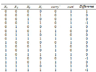
Sum' = ¯C¯ s ¯n ¯ (¯x¯1¯ ¯Ⓧ¯ ¯x¯2¯+¯x¯3¯ ¯Ⓧ¯ ¯ x¯4¯)……… (6) In the final stage, the value of Cout will change in some states, which may decrease the inaccuracy in distance provided by estimated sum and carry and also in implementation in the design of proposed system. Even though, as stated, the simplification of sum and carry raise the rate of error in the projected estimated compressor, its design complexity and hence, the power intake is greatly reduced. This can be accomplished by relating 2&4, 5&7. The first planned near compressor truth table is depicted in Table II. The output of exact compressor and approximate output of proposed inexact compressor differences is clearly shown. Out of 32 outputs in the proposed design has 12 incorrect outputs as shown in table II. This is less than the error rate using the best inexact full adder cell (2).
Cout' = ¯ (¯ x ¯ ¯ 1 ¯ ¯x¯¯ 2 ¯ +¯ ¯x¯ 3¯ ¯ x ¯4¯)……… (7)
TABLE II
TRUTH TABLE OF THE FIRSTAPPROXIMATE 4-2
COMPRESSOR
The output of the first implementation of inexact 4-2 compressor logic expressions are depicted from 5 to 7.
A delay of 3 is in the critical path of the compressor from the first proposed design of the gate level structure, so Figure 5 shows the same for the correct compressor. Hence, this design has the propagation delay lesser than the specified compressor, which is through the gates. For example, in the XOR gate, the deferral of propagation which will produce X-OR and X-NOR signals in 8, which is greater than the delay in X-NOR of the projected design. Hence, the delay of analytical path in the projected design is fewer than the correct implementation; the final number of gates in the suggested implementation is suggestively lower than the perfect specific compressor of 8.
(B) Design 2:
In this next design, to reduce the error rate and increment the accomplishment or performance, an approximate compressor is proposed. Since the Cout & carry outputs will have similar weight, the proposed equations for the inexact Cout and carry in the preceding part will be exchanged. In this proposed design, the RHS of 7 used by the carry and zero for Cin in all the stages. So, Cout and Cin should be avoided in the implementation of hardware. The inexact 4-2 compressor block diagram with the terms describe their output are shown in Figure 7
Figure 6 . Implementation at Gate level as of Design 1
Figure7 . Approximate 4-2 compressor, Design 2
[image:4.595.344.512.88.214.2]Note that Cin = 0, (9) is same as (7) and (8) is the same as (6). The gate level implementation of the subsequent projected design is shown as in figure 8. 2Δ is the delay of the critical-path inexact design, so it is 1Δ lesser than the preceding implementations; however, an additional decrease in the no of gates is consummated.
Figure 8 implementation of Gate level Design 2
The second inexact implementation truth table for a 4-2 compressor is shown in 3rd Table. This table will reveal the variance between the exact decimal values added inputs and the output values generated by the inexact compressor. For example, the inputs that are added to the decimal value will be 4 when the inputs are 1. The value of carry and sum results from the compressor by approximating it. The output in this case is 3 by using the decimal value. Table II shows the difference is -1.
TABLE III
TRUTH TABLE OF NEXT PROJECTED 4-2 COMPRESSOR
The error rate has come down to 25% since the design has only 4 incorrect outputs out of 16 outputs. The proposed design is high on accuracy when compared with other available schemes/designs which shows a very positive feature on probabilistic basis.
IV. MULTIPLICATION
In this part, the effect of utilizing the suggested compressor to multiplication is considered. The correct multiplier is called as 3 modules or parts (8).
Generation of moderate product
Addition of two operands by reducing the partial products is done by using Carry Save Address
The last calculation of the result of binary is done by a CPA.
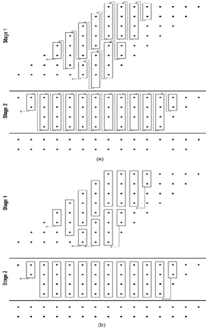
[image:4.595.62.275.467.569.2]International Journal of Innovative Technology and Exploring Engineering (IJITEE) ISSN: 2278-3075, Volume-8 Issue-9, July 2019
Figure 9. 88Dadda multiplier with Reduction circuitry, (a)
using Design 1 & (b) using Design 2 compressors
Initially, case 1 (multiplier 1), in Fig 9(a), 4-2 compressors are used in design 1.
In the second case (Multiplier 2), 4-2 compressors that are used in Design 2 will reduce in circuitry which required compressors in fewer in size since it doesn’t have Cin and Cout.
In the third case (Multiplier 3), compressors are utilized in the n-1 columns are being designed as in 1 where as 4-2 compressors are being used in the other n substantial columns.
Lastly (Multiplier 4), Design 2 has n-1 minimum substantial columns for specific 4-2 compressors and then utmost substantial columns in the contraction circuitry respectively.
To decrease the deferral and power consumption related with an exact multiplier and to expect a high error distance are the main goals of these first two approximate designs. The next inexact multipliers (Multiplier 3, 4) are planned to reduce the fault distance. Since no further development in delaying of the estimated designed when compared with an exact multiplier, the delay in these designs is determined by the compressors in critical path. However, there will be decrease in the power consumption and transistor count by utilizing the estimated compressors in the minimum important columns. There will be a lower error distance in the third and fourth design when compared with first two multipliers, which will have better performance in delay and power consumptions.
V. RESULTS
In this unit, the simulation using HSPICE, the two compressor design as shown in section III and the fourth multiplier as in section IV. In this HSPICE simulation, unlike CMOS feature sizes such as 32 nm, 22 nm and 16 nm are relatively used by the Predictive Technology Models (PTMs).
A. Approximate Compressors
XOR – XNOR gates used in the simulation at 1GHz frequency by a fan-out of 4 to the finest low-power specific compressor of [8].
PTMs at 32nm, 22nm and 16nm for the power
consumption, delay and power-delay products (PDP)
are simulated and shown in Table IV.
TABLE IV
SIMULATION RESULTS (@32 NM)
Design Delay(ps) Power(W) PDP(aJ) @32 nm
Exact Design [8] 60.36 2.98 180
Design 1 58.32 1.27 74
Design 2 44.35 1.14 50
@22 nm
Exact Design [8] 55.82 1.50 84
Design 1 56.79 0.62 35
Design 2 41.69 0.58 24
@16 nm
Exact Design [8] 47.59 0.95 45
Design 1 37.16 0.39 14
Design 2 24.44 0.36 9
As predicted, the second design has power consumption, delay and PDP which are regardless of sizes of feature with 62% faster at 16nm technology by CMOS and three feature sizes averaged to be 44% faster. Table V depicts transistors that are required in comparison to complexity of circuit measurement. Each XOR* gate uses 10 transistors, 6 transistors for XOR gate and 8 transistors for MUX gate, so in a total of 52 transistors, which reduces the complexity by 50% as revealed by the lower number of transistors. Since, the second design has no Cin and Cout with only 4 inputs and 2 outputs, the result is expected.
TABLE V
COMPARISON OF TRANSISTOR REQUIREMENT Design Number of transistors
Exact Design [8] 52
Design 1 28
Design 2 26
A. Approximate Multipliers
To simulate for n=8, the four proposed multipliers are used. For the approximate designs as well as the specified multipliers, the power consumption, delay and the transistors in number(s) is considered. The error distance is compared with other inexact multipliers.
Delay: The reduction circuitry of Dadda multiplier delay will depend on the number of declined stages and every stage delay. In first multiplier, and second multiplier, the inexact compressors are used in all columns; consequently the each stage delay is equivalent to the inexact compressors delay. Though, this can be found in Multipliers 3 and 4. There
specific multiplier since the usage of inexact compressors in the n/2 LSBs. Table VI shows the delay improvement in the reduced circuitry of each multiplier paralleled to an exact adder.
TABLE IV
SIMULATION RESULTS (@32 NM)
Design Delay(ps) Power(W) PDP(aJ) @32 nm
Exact Design [8] 60.36 2.98 180
Design 1 58.32 1.27 74
Design 2 44.35 1.14 50
@22 nm
Exact Design [8] 55.82 1.50 84
Design 1 56.79 0.62 35
Design 2 41.69 0.58 24
@16 nm
Exact Design [8] 47.59 0.95 45
Design 1 37.16 0.39 14
Design 2 24.44 0.36 9
Power Consumption: - The number and type of
compressors are used to measure the power consumption of each multiplier. Multipliers 3 and 4 will have more power consumption when compared with inexact compressors in Multipliers 1 and 2. Table VII shows the improvement in the power consumption at 32nm size in each multiplier with respect to a specified adder, which authorizes that an inexact multiplier in the reduced circuitry will result in a considerable power saving.
TABLE VII
POWER CONSUMPTION IMPROVEMENT IN REDUCTION CIRCUITRY
Design Improvement (%)
Multiplier 1 52.49
Multiplier 2 58.58
Multiplier 3 17.50
Multiplier 4 26.15
Count of transistor: -
In this paper, the count of transistor is utilized as cadent of complexity of the circuit. The first two estimated multipliers have a lower count of transistor compared with multiplier 3 and multiplier 4. The count of transistor improvement of the contraction circuitry of every multiplier correlated to specific adder.
TABLE VIII
Distance of Error: -
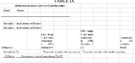
Four additional near multipliers are simulated to compare the distance of error. The multiplier 5 proposed in (7) is computed for n=8. The condensed multiplier with variable correction (multiplier 7) and the truncated multiplier with constant correction (5) (multiplier 6) are also simulated for k=1 and n=8. A further near multiplier (multiplier 8) is computed to consider the brunt of utilizing the suggested near compressors compared with other appropriate compressors.
This 8X8 Dadda multiplier utilizes the 4-2 compressors built of two near full adders (fig 3). The design of initial full-adder suggested in (1) is utilized in the near multiplier. IX
Table compiles the eight estimated multipliers measured in this document. i.e., the four expected suggested implementations and the other four near multipliers composed with their relevant structures.
TABLE IX
To compare these approximate multipliers, we used the normalized error distance (NED). The maximum highest normalized error distance is also characterized as the highest total value of normalized error distance for the case in which the fault result is greater than the exact result.
10th table displays the extreme advanced and lower normalized error distances, average NED and the number of correct result of near multiplier for n=8. The no of outputs of correct entire output specifies the possibility of precision for to each implementation. By the used of 10th table, the correctness possibility in first multiplier is 0.16% while the correctness probability in multiplier 4 is 14.3%. Since proposed near compressors produce false result for all-zero input patterns. The proposed near multiplier can produce a false result if at least one of the input is 0.
Though, those cases the multiplier can generate correct result by adding a circuit for recognize the zero-valued inputs. Accordingly, the zero-valued input patterns are not considered further in the simulation to consider the proposed multipliers for a candid comparison
TABLE X NED FOR N = 8
By the used of 10th table, 4th multiplier has the less average normalized error distance and whole near multipliers. The 4th multiplier average normalized error distance is 18 times excelling than the 7th multiplier. It has less high normalized error distance. While the near output is continually lesser when compared with the correct output, the higher normalized error distance is zero for to this implementation. Hence, this design has the lower normalized error distance within truncated implementation. The distribution of normalized error distance plot will be produced (10 fig) to analyze the accomplishment of the near
[image:6.595.310.545.108.217.2] [image:6.595.64.286.412.466.2] [image:6.595.305.546.493.609.2]International Journal of Innovative Technology and Exploring Engineering (IJITEE) ISSN: 2278-3075, Volume-8 Issue-9, July 2019
In 8x8 multiplier the range of the product is middle from the two points 0 and 65025(considered values). Whole achievable outputs are divided in 127 hiatuses; the first interval output is in middle of 513 and 1024 and etc., the last interval output is in middle of 64513 and 65025. The moderate normalized error distance of every hiatus is than calculated for the near multiplier. The multipliers 1, 2 are shown in fig 10a and 10b, at very large and very lesser product, the average NED will be increase i.e.,this near multiplier obtained on moderate in the taken output when correlated to the specified computation..
VI. APPLICATION:IMAGE PROCESSING
This proposed appropriate multipliers application is to illustrate image processing. By the using of this proposed multipliers, on the basis of pixel by pixel we can multiplied the two images. That contains two images by the single image output.
Figure 11 displays the example: The result of both input and output images will be provided. The peak SNR and the average NED i.e., based on the characteristics of image output and compared this image with the image output produced by an approximate multiplier. The equations of ME and PSNR are below.
--10
--11
In equation 10 p and m are the dimensions of image and I(i,j) and K(i, j) are the approximate and accessed values of each pixel respectively. In (11), multiplier 1
Characterizes the extreme value of each pixel.
(a)
(b)
(c)
(d)
REFERENCES
1. J. Liang, J. Han, F. Lombardi, “New Metrics for the Reliability of
Approximate and Probabilistic Adders,” IEEE Transactions on
Computers,vol. 63, no. 9, pp. 1760 - 1771, 2013.
2. V. Gupta, D. Mohapatra, S. P. Park, A. Raghunathan, K. Roy,
“IMPACT: IMPrecise adders for low-power approximate
computing,” Low Power Electronics and Design (ISLPED) 2011
International Symposium on. 1-3 Aug. 2011.
3. S. Cheemalavagu, P. Korkmaz, K.V. Palem, B.E.S. Akgul, and L.N.
Chakrapani, “A probabilistic CMOS switch and its realization by
exploiting noise,” in Proc. IFIP-VLSI SoC, Perth, Western
Australia, Oct. 2005.
4. H.R. Mahdiani, A. Ahmadi, S.M. Fakhraie, C. Lucas, “Bio-Inspired
Imprecise Computational Blocks for Efficient VLSI Implementation
of Soft-Computing Applications,” IEEE Transactions on Circuits
and Systems I: Regular Papers, vol. 57, no. 4, pp. 850-862, April 2010.
5. M. J. Schulte and E. E. Swartzlander, Jr., “Truncated multiplication
with correction constant,” VLSI Signal Processing VI, pp. 388–396, 1993.
6. E. J. King and E. E. Swartzlander, Jr., “Data dependent truncated
scheme for parallel multiplication,” in Proceedings of the Thirty
First Asilomar Conference on Signals, Circuits and Systems, pp. 1178–1182, 1998.
7. P. Kulkarni, P. Gupta, and MD Ercegovac, “Trading accuracy for
power in a multiplier architecture”, Journal of Low Power Electronics, vol. 7, no. 4, pp. 490--501, 2011.
8. C. Chang, J. Gu, M. Zhang, “Ultra Low-Voltage Low- Power CMOS
4- 2 and 5-2 Compressors for Fast Arithmetic Circuits,” IEEE
Transactions on Circuits & Systems, Vol. 51, No. 10, pp. 1985-1997, Oct. 2004.
9. D. Radhakrishnan and A. P. Preethy, “Low-power CMOS pass logic
4-2 compressor for high-speed multiplication,” in Proc. 43rd IEEE
Midwest Symp. Circuits Syst., vol. 3, 2000, pp. 1296–1298.
10. Z. Wang, G. A. Jullien, and W. C. Miller, “A new design technique
for column compression multipliers,” IEEE Trans. Comput., vol. 44,
pp. 962–970, Aug. 1995.
11. J. Gu, C. H. Chang, “Ultra Low-voltage, low-power 4-2 compressor
for high speed multiplications,” in Proc. 36th IEEE Int. Symp.
Circuits Systems, Bangkok, Thailand, May 2003.
12. M. Margala and N. G. Durdle, “Low-power low-voltage 4-2
compressors for VLSI applications,” in Proc. IEEE Alessandro
Volta Memorial Workshop Low-Power Design, 1999, pp. 84–90.
13. B. Parhami, “Computer Arithmetic: Algorithms and Hardware
Designs,” 2nd edition, Oxford University Press, New York, 2010.
14. K. Prasad and K. K. Parhi, “Low-power 4-2 and 5-2 compressors,”
in Proc. of the 35th Asilomar Conf. on Signals, Systems and Computers, vol. 1, 2001, pp. 129–133.
15. Ercegovac, Miloš D., and Tomas Lang. Digital arithmetic. Elsevier,
2003.
16. Baran, Dursun, Mustafa Aktan, and Vojin G. Oklobdzija. "Energy
efficient implementation of parallel CMOS multipliers with
improved compressors."Proc. of the 16th ACM/IEEE international
symposium on Low power electronics and design. ACM, 2010.
AUTHORSPROFILE
SHAIK ANUSHA currently pursuing Master of Technology in the department of Digital Electronics and Communication Systems from School of engineering and technology, Sri Padmavathi Mahila Viswavidyalayam. Tirupathi and her main research work focuses on VLSI, communication, and IOT based education. And she is the member of International Association of Engineers.
M Krupa Swarupa Rani, Assistant
Professor in the department of Digital Electronics and Communication Systems from School of engineering and technology, Sri
Padmavathi Mahila Viswavidyalayam.
Tirupathi Her main research work focuses on VLSI, communication, and IOT based education. And she is the member of
![Figure 1.Schematic diagram of n-2 compressors in a multi operand addition circuit [13] Where Ψj indicates the carry bits number of slice ‘i’ to i+j’](https://thumb-us.123doks.com/thumbv2/123dok_us/8193313.258634/2.595.324.508.101.554/figure-schematic-diagram-compressors-operand-addition-circuit-indicates.webp)