Abstract Background/Objectives: A location tracking system has been developed in order to tracks the location of a moving terminal and provide various tracking services based on the location.
Methods/Statistical analysis: This paper presents a method to find a target using UAVs in LoRa communication environment. The proposed method proposes a UAV flight path where the target signal can be found without blind spots. The flight path was changed by using the intensity of the transmitted signal during the flight using the variation of the signal strength.
Findings: We verified the proposed method by simulation and confirmed that it takes a long time to track the target, although the efficiency of the 3 flights is high. It is best to fly three UAVs to reduce time to find target and increase efficiency when the time is a critical factor. The LoRa communication lowers the production cost and makes it possible to construct the system with low cost.
Improvements/Applications: The proposed method provides the location-based service collecting location target information on the terminal and provides various services such as route guidance, prevention of crime, or finding a missing child.
Keywords: Localization, UAV, Trigonometric measurement, Tracking, Signal Strength
I. INTRODUCTION
In recent years, a location tracking system has been developed so as to track the location of a moving terminal and provide various location-based services based on the location. A server providing the location-based service collects a location information on the terminal, And provides various services such as route guidance, prevention of crime, or finding a child[1-3].
The terminal can recognize the latitude and longitude of the terminal using a GPS (Global Positioning System) or a base station, and transmit the generated location information to the server. However, if the communication with the user terminal is lost in the process of collecting the location of the mobile terminal on the server side, it becomes difficult to track the location, thereby causing the problem of the location related service being interrupted[4-8].
In the case of the GPS position tracking system, an error of up to 3M may occur when the LOS (Line Of Sight) between the terminal and the GPS satellite is secured, but when the terminal moves to an area where the LOS between the user terminal and the satellite is not secured. There is a problem
Revised Manuscript Received on May 22, 2019.
SungkwanYoum, Department of Information & Communication Engineering, Wonkang University, Iksan, Jeonbuk 54538, Korea
that it becomes difficult to grasp the position of the mobile terminal[9-11].
The location tracking system that provides the existing location has a problem that it is difficult to keep the reliability of the system because it is difficult to continuously locate the terminal and the information is disconnected. Also there is a problem in providing a stable service. In the case of a location tracking system using a communication network such as LoRa used in the recent IoT network, it is possible to avoid the communication disconnection occurring in the GPS positioning system. In the case of the base station location tracking system, the proposed methods could be added and overcome. In addition, LoRa lowers the production cost and makes it possible to construct the system with low cost.
In this section, we explain the proposed system and algorithm in Section 2, analyze the performance in Section 3, and finally conclude in Section 4.
II. THEPROPOSEDTARGETLOCALIZATION
METHOD
[image:1.595.366.495.517.691.2]Figure 1 shows the configuration of the position tracking system using the unmanned aerial vehicle in this paper. As shown in the Figure 1, the position tracking system communicates with at least one of the unmanned aerial vehicle group composed of a plurality of unmanned aerial vehicles and the plurality of unmanned aerial vehicles server.
Figure 1.Configuration of Location Tracking System The number of the plurality of unmanned aerial vehicles constituting the unmanned aerial vehicle group is preferably at least three, and is composed of one master and several slaves. In addition, the
communication network can support various WPANs. In
Location Tracking Method using
Communication Signal Strength
particular, a LoRa communication scheme can be applied. The location tracking server can store the identification information of the terminal held by the target to be tracked. The control information including the identification information may be transmitted to a plurality of unmanned aerial vehicles to control movement of the plurality of unmanned aerial vehicles to the position of the moving terminal.
In this case, the target may be a user who is subject to location tracking, and the target terminal may include various mobile terminals supporting smartphone communication, a smart phone, a wearable device (e.g., a watch type terminal Such as Smartwatch, Smart Glass, HMD (Head Mounted Display), and various IoT (Internet of Things) terminals.
Accordingly, in order to move to the position of the terminal according to the control information, the plurality of unmanned aerial vehicles may generate message information such as Ping based on the identification information of the terminal included in the control information, and transmit the message information to the terminal through the communication network.
When any one of the plurality of unmanned aerial vehicles is preset as a master and receives control information from the location tracking server, it is possible to control the driving of each of the other unmanned aerial vehicles previously set in the slave according to the control information. Thus, a plurality of unmanned aerial vehicles can be formed as one unmanned aerial vehicle group.
Also, the master flight object, which is a master unmanned aerial vehicle set as a master, transmits control information received from the position tracking server to each slave flight object which is a unmanned air vehicle set as a slave belonging to the unmanned air vehicle group corresponding to the master flight object, It may be generated and transmitted to the terminal, or may be driven and operated according to the control information.
Also, the mutual communication between the different unmanned aerial vehicles belonging to the unmanned aerial vehicle group can be performed through short distance communication, and the master aviation body can control each slave aviation body through short distance communication to control the flight. At this time, it is possible to communicate with each other by the BLE method between different unmanned aerial vehicles belonging to the unmanned aerial vehicle group, and various short-range wireless communication methods can be applied.
It is needless to say that the master flight vehicle can control the moving direction and the flight route of each unmanned air vehicle belonging to the unmanned air vehicle group according to the control information received from the location tracking server. Each unmanned aerial vehicle supports GPS communication so that the master aviation body adjusts the distance between the different unmanned aerial vehicles belonging to the same unmanned aerial vehicle group at a preset distance based on the own position information and the position information of each slave air vehicle.
The terminal verifies whether the message is a message transmitted to the terminal based on the identification information included in the message information when receiving the message information through the communication network. In the case of a message transmitted to itself, a response signal for responding to the message information may be transmitted to the unmanned aerial vehicle corresponding to the message information.
Each unmanned aerial vehicle belonging to the unmanned aerial vehicle group can measure the signal strength when receiving the response signal. The master flight vehicle collects information on the signal strength through short-distance communication with each slave flight vehicle, determines the direction in which the terminal is located according to the signal strength, determines the direction of travel, and moves to the position of the terminal.
The master flight entity can generate the message information as a message for the ping test, and the terminal corresponding to the receiver of the message according to the message information can transmit the response signal corresponding to the message.
The master flight body belonging to the unmanned aerial vehicle group can transmit the message information to the terminal periodically or in real time. Accordingly, when there is a difference between the measured signal intensities of the respective slave aircraft, it is possible to move while tracking the direction corresponding to the position of the moving terminal by changing the moving direction.
The master flight vehicle determines that the signal strength of each unmanned aerial vehicle of the unmanned aerial vehicle group arrives at the position of the terminal when the signal strength is equal to or greater than a predetermined first reference value. The master flight vehicle measures the position of the terminal by means of a predetermined position measurement algorithm such as triangulation based on the signal strength measured through communication with the terminal and the position information of each unmanned air vehicle in each unmanned aerial vehicle belonging to the unmanned aerial vehicle group do. After generating the terminal location information for the location of the terminal, it can be transmitted to the location tracking server.
The master flight vehicle can fly with each slave airplane while tracking the terminal by changing the direction of movement according to the difference of the signal intensity so that the signal strength with the terminal is maintained above the predetermined first reference value. It is possible to generate terminal location information for the terminal moving periodically or in real time and transmit it to the location tracking server.
In this paper, we can continuously monitor the location of the terminal by using multiple unmanned aerial vehicles. The position and movement route of the moving terminal can be easily grasped according to the continuous tracking of the terminal by the plurality of
terminal can be improved.
In this paper, it is possible to minimize the power consumption of the terminal and to support the tracking of the terminal for a long time by supporting the location information of the terminal to be transmitted to the location tracking server by only communicating with the unmanned aerial vehicle.
The detailed operation of the position tracking system using the unmanned aerial vehicle according to the embodiment of the present invention will be described with reference to the drawings.
[image:3.595.74.271.232.377.2]As shown in Figure2, the unmanned aerial vehicle includes a communication unit, a control unit, a driving unit, and a sensor unit.
Figure 2.Position Tracking System
It is needless to say that the communication unit, the control unit, the driving unit, and the sensor unit may be integrated into the control unit, and that various other configuration units may be additionally provided or any one of the configuration units may be included in the other configuration units.
The communication unit may include a wireless communication unit for supporting communication with the position tracking server and the terminal through the communication network, and a GPS unit for measuring the current position of the wireless air vehicle. At this time, the wireless communication unit can also support short-range communication with other unmanned aerial vehicles.
The driver can operate the unmanned aerial vehicle to fly and fly. The controller included in each unmanned aerial vehicle generates message information based on the control information received from the position tracking server or other unmanned aerial vehicle through the communication unit. The message information can be transmitted to the terminal through the communication unit. The message information can be periodically generated from the time when the control information is received and transmitted to the terminal.
The controller included in each unmanned aerial vehicle can measure the signal strength based on the response signal received from the terminal through the communication unit after transmitting the message information.
The control unit is set in advance as either a master or a slave, and operates the unmanned aerial vehicle as a master airplane or a slave airplane. Accordingly, as shown in the drawing, any one of the plurality of unmanned aerial vehicles may be set as the master, and other unmanned aerial vehicles
other than the master may be set as the slave.
The control unit configured by the master flight body generates message information upon receiving the control information from the location tracking server and transmits the message information to the terminal through the communication unit. Control information is transmitted to each slave flight object, the controller configured in the slave flight object generates the message information according to the control information, and generates message information at the same time as the message transmission time of the master flight object. By transmitting the information through the communication unit of the slave flight vehicle, it is possible to synchronize the transmission timing of the message information of each unmanned aerial vehicle.
The control unit configured in the master flight unit can drive the unmanned air vehicle by controlling the driving unit based on the control information received from the position tracking server and can transmit driving information for controlling flight to each slave air vehicle through the communication unit.
The control unit configured in each slave flight body can control the driving unit of the slave flight body according to the driving information to move the slave flight body in the same moving direction as the master flight body. The signal strength according to the response signal when the response signal is received from the terminal through the communication unit configured on the slave flight body can be measured. The signal intensity information for the signal strength can be transmitted to the control unit configured in the master flight body through the communication unit configured in the slave flight body.
The control unit configured in the master flight body receives the signal strength information about the signal strength measured in each slave flight body from each slave flight body, and determines the moving direction based on the signal strength of the slave flight body and the signal strength of each slave flight body. And drives the master flight body through the driving unit so as to move according to the determined moving direction. It is possible to generate driving information so that each slave air vehicle moves in the same moving direction as the moving direction of the master air vehicle and transmit the driving information to each slave air vehicle.
The control unit configured in the master flight unit generates the position information through the communication unit. It is possible to stabilize flight by adjusting the separation distance between different unmanned aerial vehicles belonging to the unmanned aerial vehicle group based on the positional information received from each slave air vehicle in real time or periodically through communication with each slave air vehicle.
The control unit of the slave flight vehicle receives the driving information transmitted from the master flight vehicle through the communication unit and controls the driving unit of the slave
flight vehicle can fly the flight by being spaced apart by a predetermined distance according to the driving information with the other flight vehicle. In addition, the control unit of the slave aircraft may control the driving unit to change the moving direction of the slave aircraft when the moving direction is changed according to the driving information.
A master flight body controls each slave flight body so that a plurality of unmanned aerial vehicles constitute one unmanned aerial vehicle group and a plurality of unmanned aerial vehicles belonging to the unmanned aerial vehicle group can fly a flight.
The control unit of each unmanned aerial vehicle belonging to the unmanned aerial vehicle group may control the driving unit based on the control information received from the position tracking server to fly the vehicle. In other words, the group of unmanned aerial vehicles can fly according to the control of the location tracking server.
The sensor unit may include various sensors to generate attitude information and moving direction information for the x, y, and z axes of the unmanned aerial vehicle, and provide the information to the control unit. The control unit can control the posture and the moving direction of the unmanned air vehicle based on the attitude information and the moving direction information. At this time, the sensor unit may include various sensors such as a gyro sensor, an acceleration sensor, an altitude sensor, a speed sensor, and the like.
The control unit of the master flight vehicle can receive posture information and movement direction information from each slave flight vehicle through the communication unit. The driving information for correcting the moving direction of each slave air vehicle can be transmitted to each slave air vehicle based on the posture information and the moving direction information of the slave air vehicle.
[image:4.595.349.514.466.570.2]Referring to FIG. 4 to FIG. 7, the operation configuration of the movement direction change for moving to the position of the terminal according to the position change of the mobile terminal of the unmanned aerial vehicle group will be described.
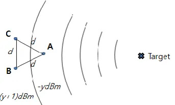
Figure 3.Triangular Formation of Three UAVs As shown in Figure 3, each unmanned aerial vehicle belonging to the unmanned aerial vehicle group transmits message information to the terminal. Each unmanned aerial vehicle belonging to the unmanned aerial vehicle group can receive the response signal to the message information from the terminal and measure the signal strength.
The master flight body belonging to the unmanned aerial
vehicle group is positioned at the head of the squadron of the flight, and each slave flight body can be controlled to fly by being positioned at the rear end of the dash through short distance communication.
Master flight objects receive position information from each slave flight object. Driving information for changing the position of the slave air vehicle may be transmitted to each of the slave air vehicles according to a predetermined contour pattern based on the own position information and the position information of the slave air vehicle to maintain the contour pattern.
The master flight vehicle receives the signal strength information generated by measuring the signal strength according to the response signal transmitted from the terminal from each slave flight body. It is possible to determine the direction in which the terminal is located based on the difference in signal intensity measured in each of the different slave aircraft depending on the signal intensity information of each slave aircraft and determine the direction as the direction of travel.
[image:4.595.90.262.561.664.2]As shown in Figure 4, the master aircraft can compare signal strengths corresponding to different slave aircrafts based on the signal strength information received from the different slave aircraft. If there is a difference in signal strength according to the comparison, it identifies the slave aircraft with higher signal strength. The master flight body sequentially rotates the main beam pattern at predetermined angular intervals in a direction in which the slave aircraft having the higher signal strength is located based on the master flight vehicle. The unmanned aerial vehicle can be moved to the positions of the unmanned aerial vehicles corrected according to the rotation of the major pattern.
Figure 4.Target Estimation
The master flight body can receive position information from each slave flight body to change the travel direction. It is possible to identify the direction in which the slave air vehicle having the higher signal intensity is located compared with the own position information.
Figure 5.Distance Calibration
The master flight body may sequentially rotate at predetermined angular intervals in the yaw direction with respect to a predetermined center axis for rotation of the major pattern to correct the movement direction. When the moving direction is corrected, the slave aircraft is moved to the rear of the main pattern based on the position of the slave aircraft in order to maintain the preset pattern for flight formation based on the own position information and the position information of each slave aircraft. . It is possible to change the position of each slave flight body so as to correspond to the rotated main pattern according to the change of the moving direction, thereby rotating the main pattern.
The master flight control unit controls the slave aircraft so as to measure the signal intensity of the message transmitted to the terminal at each position of the slave device changed according to the rotation of the main pattern every time the rotation angle of the predetermined pattern is rotated at a predetermined angle interval. It is possible to move the unmanned aerial vehicle group in the determined moving direction by determining the direction of the master flight body when the difference in the signal intensity measured in each of the different slave aircrafts is equal to or less than the predetermined second reference value as the moving direction. At this time, the second reference value may be zero.
The master flight vehicle can change the angle at a predetermined time interval when the direction of movement is changed due to a difference in signal intensity between different slave aircrafts.
The master aircraft can control each unmanned air vehicle belonging to the unmanned aerial vehicle group to transmit a message and receive a response signal at each angle change. Accordingly, it is possible to receive information on the signal intensity measured after the angle change from each slave flight body, and calculate the difference by comparing the signal intensities corresponding to the different slave flight bodies for each changed angle.
As shown in Figure 6, when the terminal moves from the existing position and stray from the flight direction of the unmanned air vehicle, the unmanned air vehicle can move by modifying the moving direction according to the position change of the terminal.
Figure 6.Direction Correction
For example, each unmanned aerial vehicle belonging to the unmanned aerial vehicle group transmits message information periodically or in real time to the terminal while moving to the terminal position. And the signal strength corresponding to the response signal is periodically or real-time measured in all the unmanned aerial vehicles belonging to the unmanned aerial vehicle group.As shown in Figure 6, the master flight vehicle periodically or real-timely compares the measured signal strengths of the different slave flight vehicles on the move. When the mutual difference occurs, the moving direction is changed to a predetermined angular interval as described above in the direction in which the slave air vehicle having the higher signal intensity is located, as described above. It is possible to control each slave device so as to rotate the preset pattern and to move to the position of each slave device changed in accordance with the rotation of the major pattern.
When the difference in signal intensity measured in each slave aircraft whose position is changed is less than a predetermined second reference value, the master flight vehicle determines its own moving direction as the final moving direction and can change the moving direction according to the positional variation of the terminal.
When the final moving direction is determined, the master flight vehicle transmits driving information to each slave device, and controls each slave device to move in accordance with the final moving direction while maintaining the main pattern. As described above, the master flight body can control the movement direction and the separation distance by controlling the slave flight body belonging to the unmanned aerial vehicle group of the master flight body through the short distance communication when the travel direction is changed.
In this paper, the unmanned aerial vehicle also changes the direction of movement according to the movement of the terminal, so that the unmanned aerial vehicle can easily move to the position of the mobile terminal even when the terminal is moved..
The plurality of unmanned aerial vehicles can automatically determine whether or not they have arrived at the location of the terminal. When the terminal arrives at the location of the terminal, the location information of the terminal is generated
[image:5.595.104.250.55.145.2]continuously provided to the location tracking server. This is explained in detail in <Figure 8> and <Figure 10>.
[image:6.595.106.243.182.335.2]As shown in Figure 7, the master flight body controls the unmanned aerial vehicle group and moves to the terminal position. If the signal intensity of all the unmanned aerial vehicles belonging to the unmanned aerial vehicle group corresponding to the master air vehicle is equal to or greater than the predetermined first reference value, it can be determined that the master air vehicle has reached the position of the terminal.
Figure 7.Target Localization
The master flight vehicle uses the triangulation method as shown in Figure5 based on the measured signal strength and position information of each unmanned aerial vehicle on all unmanned aerial vehicles belonging to the unmanned aerial vehicle group. It can generate location information for the terminal and can transmit it to the location tracking server.
The master flight vehicle can track the terminal while adjusting the direction of movement so that the signal intensity of all the unmanned aerial vehicles belonging to the unmanned aerial vehicle group (1) is maintained above the predetermined first reference value. The location information of the terminal can be generated periodically or in real time and transmitted to the location tracking server. At this time, the master flight vehicle compares the difference of the signal intensity measured in each slave flight with a preset second reference value. It is possible to track a moving terminal through a method of changing the moving direction.
The master flight vehicle can track the moving terminal by a method of comparing the difference of the signal intensity measured in each slave flight body with a preset second reference value and changing the moving direction. The location tracking server can continuously track the terminal based on the location information received from the master air vehicle, and can also generate route information for the terminal travel route by collecting the location information.
A control unit of the master flight vehicle may be configured in the location tracking server. Accordingly, the location tracking server can control each unmanned aerial vehicle by transmitting control information to all the unmanned aerial vehicles belonging to the unmanned aerial vehicle group. And receives signal strength information from each unmanned aerial vehicle belonging to the unmanned aerial vehicle group. The moving direction of each unmanned aerial vehicle belonging to the unmanned aerial
vehicle group can be determined or the moving direction can be changed as described above based on the signal strength of each unmanned aerial vehicle. Each unmanned aerial vehicle belonging to the unmanned aerial vehicle group can transmit the generated signal strength information by measuring the signal strength according to the response signal from the terminal periodically or in real time to the location tracking server.
In addition, the location tracking server determines that the signal strength of all unmanned aerial vehicles belonging to the unmanned aerial vehicle group arrives at the position of the terminal when the measured signal strength is equal to or greater than a predetermined first reference value, It is possible to track the position of the terminal through triangulation and to control each unmanned air vehicle belonging to the unmanned aerial vehicle group to move according to the movement path of the terminal.
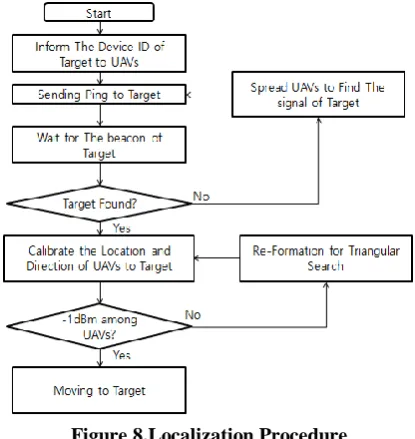
Figure 8shows a flowchart illustrating a method of tracking a location of a terminal according to an exemplary embodiment of the present invention.
Figure 8.Localization Procedure
As shown in the Figure 8, at least one of the plurality of unmanned aerial vehicles receives control information including identification information about the terminal carried by the terminal through the communication network from the location tracking server. The plurality of unmanned aerial vehicles can be moved to the position of the terminal according to the control information.
A plurality of unmanned aerial vehicles periodically transmits a message including identification information according to control information through a communication network. The signal strength can be measured by receiving a response signal corresponding to the message from the terminal receiving the message.
A master flight set as a master among a plurality of unmanned aerial vehicles collects measured signal strengths from each slave flight vehicle through mutual close-range communication with each
[image:6.595.327.535.307.527.2]is possible to move to the position of the terminal by setting the moving direction according to the difference of the signal intensity of the different slave air vehicles.
The master flight vehicle periodically compares the signal strengths of the different slave flight vehicles during the movement of the plurality of unmanned aerial vehicles, and when the difference occurs, the direction of travel is shifted in a direction in which the slave flight vehicle having a higher signal intensity is located, Can be changed. The plurality of unmanned aerial vehicles can be moved to the position of the terminal by changing the direction of movement of the plurality of unmanned aerial vehicles in the direction when the difference in signal intensity is equal to or less than a preset second reference value.
The master flight vehicle may transmit the position information through a preset position measurement method based on the signal strength measured according to communication between the plurality of unmanned aerial vehicles and the terminal when the signal strength measured in each unmanned aerial vehicle is equal to or greater than a predetermined first reference value. The terminal can be continuously tracked by tracking the terminal so that the signal intensity of each unmanned aerial vehicle is maintained above the first reference value.
[image:7.595.363.510.54.190.2]III. EXPERIMENTALRESULTS
Table 1: Initial Set of features used for the experimentation
Parameters Value
Tx power 14 (dBm)
Maximum transmission range 700 (meters) X asxis of simulation ground
field
-1000<x<1000 (meters) Y asxis of simulation ground
field
-1000<y<1000 (meters) Initial speed of UAV 10 (m/s)
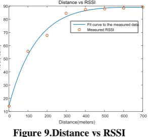
This section verifies the proposed location tracking system. In order to verify the proposed system, UAV and target position are specified in the terrain without obstacle to find the target point. UAV to fly flight. If the target signal is not detected at the starting point, the target signal is detected first if the signal is detected first and if not, if the direction is set. When the signal of the target is detected, it moves to the location of the UAV where the signal is detected, and the proposed flight is performed at that point. For this simulation, the RSSI value was used as the distance measured from the field experiment in the LoRa network. We created a function based on the measured value and output the RSSI value with the input value of the function as the distance value. The function is
(1)
[image:7.595.321.538.252.837.2]where a, b, c, and d can be obtained by inputting actual RSSI data and distance values. The resulting value appears as Figure 9.The simulation parameter sare carried out using Table 1.
Figure 9.Distance vs RSSI
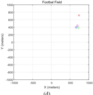
If there are three UAVs in the simulation test, if the target signal does not occur, it moves until it detects the target signal and searches until the signal is detected. Figure 10 shows the process of three UAVs seeking targets in target detection using UAV from (a) to (d) consequently.
(a)
(b)
(d)
Figure 10.Target detection using UAVs When three UAVs move in the direction of 120 degrees, a blind spot is generated and the target signal can not be detected at all, so a search path must be given to detect the signal. In the case of four or five units, when moving to different directions and sensing a target signal, the user may go to a blind spot where the target signal can not be detected. In order to prevent such a case, this paper minimizes energy waste of UAV by efficiently setting flight path. This is because the energy efficiency is lowered and the path optimization is not performed in the case of a sudden turn in the direction of the UAVs. In this paper, we set the optimal path for finding the target signal by setting the movement path for each flight.
The UAV flight path to find the target signal represents the flight path to find the target signal according to the number of UAVs. In Figure 11 (a) we construct a trajectory by dividing each circle by the number of UAVs in a circle composed of three UAVs, and set up a UAV flight path corresponding to the trajectory. Whenthe circlesare divided by fourUAVs and five UAVs, the trajectory is drawn as shown in Figure 11 (b) and 11 (c). In the last figure (d), if there are five UAVs, two UAV flight paths are shown. In case of flying as shown in the figure,
(a)
(b)
(c)
[image:8.595.349.512.55.564.2](d)
Figure 12.Time to Find Target's Signal
Looking at the Figure 12, the UAV head shows the distance to find the target. If you look at the distance, you can see that the farther the distance of the target is, the longer the flight distance is needed to find it, and the UAV takes off and detects the signal. And if the UAV signal cannot be found, the flight distance is increased, which is the distance required to find the signal. The distance required to find the target depends on the number of UAVs. This is because it takes time to find the target signal for the first time. In this figure, the distance is determined by the time required to find the UAV signal.
[image:9.595.64.227.53.192.2]Figure13.FlightDistance to Find Target Looking at the time it takes to find a picture target in Figure 14, the flying distance increases dramatically at 700 meters. This indicates the time required for the search. If the distance is not more than 700, the difference in the search path of the flights is not significant. The reason for the longest time to find the target when moving from the figure to the 4th flight is because the time required for the 4th flight to reach the position of the opposite dragon after finding the target is the longest. This is because the time taken by the UAVs coming from the opposite side is long when the signal is found in the case of the flight of four flights.
Figure 14.Triangular Flight Time to Find Target If you search for a target with three flights after searching
[image:9.595.336.517.104.250.2]for a signal, the five UAVs find the fastest and the three UAVs take the longest. Considering the movement of the UAV to the target signal seeking point, moving to the third flight reduces the overall search time in Figure 14.
[image:9.595.329.514.356.527.2]Figure 15. Traveled Distance of all UAVs When all UAVs are moved, all UAVs traveled to identify all flight paths to determine the efficiency of the system. Figure 15 shows that the number of flight paths increases with the number of UAVs. The entire flight path is constantly increasing with distance, and in the figure, it is time to find a reason signal that increases rapidly when it is over 700 meters.
Figure 16.Flight Efficiency The efficiency is defined as the following.
(2)
Efficiency was defined and efficiency was verified by dividing the defined efficiency by the time it took to find the target for every path traveled by the UAVs. Figure 16 shows that 3 flights are efficient and 4 flights are more efficient in case of 700m. It can be seen that if the distance is farther away, fast searching for the target can lower the entire travel route, and if the distance of the other target is getting farther, the three cars are more efficient.
IV. CONCLUSION
This paper presents a method to find a target using UAV in LoRa environment. The proposed method proposes a UAV flight path so that the target signal can be found without blind spots. The flight path was
[image:9.595.90.252.630.761.2]flight, using the change of the signal strength. We verified the proposed method by simulation and confirmed that it takes a long time to find the target, although the efficiency of the 3 flights is high. It is best to fly three squadrons to increase the number of UAVs and increase efficiency when time is important.
REFERENCES
1. Rajnarayan DG, Ghose D, Multiple agent team theoretic decision-making for searching unknown environments. In Proceedings of the IEEE Conference on Decision and Control, Maui, Hawaii, Dec 2003 : 2543–2548.
2. Sujit, PB, Ghose D, Search using multiple UAVs with flight time constraints IEEE Trans. Aerosp. Electron. Syst. 402 2004491–509. 3. Ryan A, Hedrick JK, A mode-switching path planner for UAV-assisted
search and rescue. In Proceedings of the IEEE Conference on Decision and Control, Seville, Spain, Dec 2005 :1471–1476..
4. Sethi P, Sarangi SR, Internet of Things: Architectures, Protocols, and Applications,Hindawi Publishing Corporation:2017 :1-25.
5. KimDH, Lim JY, Kim JD, Low-Power, Long-Range, High-Data Transmission Using Wi-Fi and LoRa, 6th International onference on IT Convergence and Security.2016 : 1-3.
6. Anand P, Towards Evolution of M2M into Internet of Things for Analytics, IEEE Recent Advances in Intelligent Computational Systems,2015: 388-393.
7. Gupta R, Gupta R,ABC of Internet of Things : Advancements, Benefits, Challenges, Enablers and Facilities of IoT, Symposium on Colossal Data Analysis and Networking, 2016 : 1-5.
8. Nolan KE, Guibne W, Kelly MY,An Evaluation Of Low Power Wide Area Network Technologies For The Internet Of Things, International Wireless Communications and Mobile Computing Conference,2016: 439-444. 9. So J, Kim D, Kim H, Lee H, Park S,LoRaCloud: LoRa Platform on
OpenStack, 2016 IEEE NetSoft Conference and Workshops. 2016: 431-434.
10.Petajajarvi J, Mikhaylov K, Hamalainen M, Iinatti J, Evaluation of LoRa LPWAN Technology for Remote Health and Wellbeing Monitoring, 10th Internasional Symposium on Medical Information and Communication.2016: 1-5.