Abstract: Background/Objectives: In this study, seismic safety of piping is analyzed by applying 0.5g ground acceleration to sprinkler piping. It is the purpose of this study to confirm the improvement of seismic safety depending on whether multi-joint application with plastic deformation is possible through seismic safety analysis. Methods/Statistical analysis: The static analysis method was used as the analysis method and the safety of the piping was compared according to the presence or absence of joints capable of plastic displacement. Sprinkler installation piping was analyzed based the general installation standards of piping. Findings: As a result of analyzing the stresses without joints, it was found that the allowable stress exceeded in some sections of the pipe, and that the safety was not being secured in case of earthquakes. As a result of analyzing the stress of the pipe where the joint is installed, it is understood that the stress and the displacement are interpreted within the range of allowable stress and the safety of the pipe can be ensured when the earthquake occurs. Stress generated in the piping during the earthquake are not constantly generated at certain intervals, but are interpreted differently depending on the installation conditions of the piping and the type of load. In addition, due to the concentrated stress generated in part of the pipeline, serious damage can occur when an earthquake occurs, which can seriously affect the performance of the fire fighting system.
Improvements/Applications: In order to solve this problem, it is necessary to analyze the safety of the structure of the piping and to secure safety against earthquakes by installing a device capable of actively bearing the stress and displacements in areas where problems may occur. And, through installation of multi joint which can generate plastic deformation in piping, if it can be generated at the time of earthquake, it could absorb stress and displacement and improve earthquake safety
Index Terms: Joint, Pipe Stress, Plastic Displacement, Seismic Performance, Sprinkler Facility, Static Analysis
I. INTRODUCTION
Recently, much attention has been focused on the seismic safety of structures due to the construction of high-rise buildings. However, when an earthquake occurs, the importance of not only the structural problems of buildings but also the safety of non-structures in buildings is increasing. As the focus of the possibility of triggered fire as an aftermath of an earthquake increases, the importance of seismic analysis of fire-fighting facilities among non-structures is gaining its importance.
Revised Manuscript Received on May 13, 2019.
Jae-Ou Lee, Department of Fire and Disaster Prevention, Daejeon
University, Daejeon city, Korea, [email protected], +82-10-4691-3456
Ka-Young Oh, Department of Fire and Disaster Prevention, Daejeon
University, Daejeon city, Korea, [email protected]
In the case of fire-fighting facilities, there are many problems due to the specification focused design method that restrains the movement of the piping rather than the engineering design method by analyzing the stress or displacement of the piping material [1,2]. When an earthquake occurs, the piping is not able to be separated and analyzed at every interval. Since all of the piping is integrated, it is necessary to analyze the stress and displacement of the entire piping. However, the seismic design criteria of fire-fighting facilities do not reflect this, and it is designed in such a way that longitudinal and transverse braces are installed at certain intervals to restrain its motion. This limits the accuracy of engineering analysis [3,4]. The design guidelines for seismic design of the American Society of Civil Engineers(ASCE) piping, which has been adopted by NFPA, proposed four design methods. Static Hand Calculations, Static System Analysis, and Response Spectra Analysis[5,6] are the Cook Book that can be designed with no engineering knowledge, and Static Hand Calculations, which analyzes the behavior of piping engineering.
When the ground acceleration is transferred to the piping, the piping generates torsional stress, bending stress and displacement due to the transmitted force. Therefore, rather than analyzing the force transmitted to the strut as in the seismic design standard of the fire-fighting facility, it is more reasonable to design them [7,8]. The strut method is a designing method that does not take into account the physical properties of the piping material. Most of the engineers of the piping system prefer to use the ball joints or slide joints that actively support and respond to stress and displacements. Therefore, for reasonable and reliable seismic design, it is necessary to understand the characteristics of piping and interpret the assumption of various types of loads that can transmit the ground acceleration [9, 10].
In this study, it is assumed that the earthquake safety is first evaluated by using the Static System Analysis method with 0.5g ground acceleration applied to the sprinkler installed pipe. Secondly, we are to assume that a joint that is capable of plastic displacement is installed in the region where the stress is concentrated to evaluate the safety from an earthquake.
Comparison of Methods to Improve Seismic
Performance Depending on the Use of Expansion
Joint
II. MATERIALSANDMETHODS
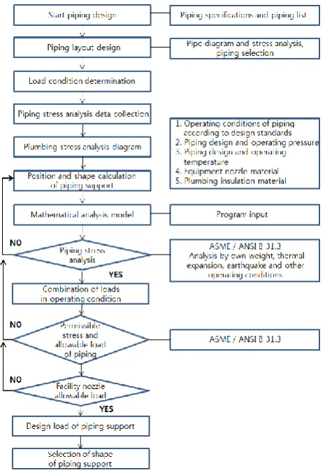
[image:2.595.318.545.54.181.2]The loads to be considered in piping design are classified into fixed load, live load, snow load, wind load, earthquake load, earth pressure and ground water pressure, temperature load, fluid pressure and container contents load. In addition to the fixed load of the piping system, which is a double structure, applicable loads are earthquake load, earth pressure and ground water pressure, temperature load and fluid pressure. The primary purpose of engineering stress analysis is to examine the safety of the piping system and the load of the piping such as internal pressure, thermal expansion, self weight, wind, and earthquake, and to design the piping support and its fixture. Figure 1 is a chart to demonstrate the flow of the seismic design of the pipeline, which reflects the feedback to the final design until safety is verified.
Fig. 1. Seismic piping design flowchart
Figure 2 shows the isometric diagram of the sprinkler system installed in the building. The analysis conditions were as follows: pipe schedule number 10, pipe nominal diameter 80mm, water temperature 30°C, water pressure in
pipe 10㎏/㎠, hydraulic test pressure 15㎏/㎠ are assumed to be installed at intervals of 3m.
Fig. 2. Isometric diagram for seismic analysis
[image:2.595.56.289.257.597.2]The analysis of the piping is based on the ASME B31.3 "Code for pressure piping", and is based on 11 load conditions as shown in Table 1 under the condition that the ground acceleration is 0.5g. In order to compare the seismic safety according to the joint use, we analyzed the safety of the pipeline by comparing the analytical values according to joint application.
Table 1: Listing of Static Load Cases for this Analysis [2]
No Statu
s Load case No
Statu
s Load case
1 OPE L1=W+T1+P
1 7 OCC L7=L3-L1
2 OPE
L2=W+T1+P 1 +U1+U3
8 OCC L8=L4-L1
3 OPE
L3=W+T1+P 1 -U1-U3
9 OCC L9=L5+L6
4 OPE
L4=W+T1+P 1 +U1-U3
10 OCC L10=L5+L7
5 SUS L5=W+P1 11 OCC L11=L5+L8
6 OCC L6=L2-L1
Note:
OPE: analysis assuming operating conditions,
SUS: analysis taking into account the influence of weight and pressure
EXP: analysis considering the effect of heat
OCC: analysis assuming a state where a short-term load is applied
W: weight, T1: temperature, P1: pressure, U1: X-axis direction, U2: Y-axis direction, U3: Z-axis direction
Table 2 shows the relationship between the ground acceleration and the MMI (Modified Mercalli Intensity Scale) which is commonly used. In the case of 0.5g, the magnitude corresponds to the magnitude 8 when converted to the corrected mercury
[image:2.595.304.552.327.561.2]U1, U2, and U3 are shown in Figure 3.
Table 2: Modified Mercalli Intensity Scale and Maximum Acceleration [2]
Maximum Acceleration MMI Value
0.002 or more and less than 0.004 Ⅰ
0.004 or more and less than 0.008 Ⅱ
0.008 or more and less than 0.017 Ⅲ
0.017 or more and less than 0.033 Ⅳ
0.033 or more and less than 0.066 Ⅴ
0.066 or more and less than 0.133 Ⅵ
0.133 or more and less than 0.264 Ⅶ
0.264 or more and less than 0.528 Ⅷ
0.528 or more and less than 1.050 Ⅸ
1.050 or more and less than 2.100 Ⅹ
[image:3.595.48.282.104.482.2]Fig. 3. Coordinate reference
[image:3.595.49.279.115.327.2]Figure 3 shows the coordinate values of the U1, U2 and U3 axes in Table 2 and Table 3, various stress and displacements are analyzed. In general, the direction of arrangement of the axes in the U1, U2 and U3 axes is limited to two directions.
Table 3: Stress and Displacement of Load Case Analysis
Divisio n
Load
case Solution
OPE 1 L2=W+T1+P1
OPE 2 [L2=W+T1+P1+U1(X)+U3(Z)]
OPE 3 [L3=W+T1+P1-U1(X)-U3(Z)]
OPE 4 [L4=W+T1+P1+U1(X)-U3(Z)]
SUS 5 L5=W+P1
OCC 6 L2-L1=U1(X)+U3(Z)
OCC 7 L3-L1=-U1(X)-U3(Z)
OCC 8 L4-L1=U1(X)-U3(Z)
OCC 9 L5+L6=W+P1+U1(X)+U3(Z)
OCC 10 L5+L7=W+P1-U1(X)-U3(Z)
OCC 11 L5+L8=W+P1+U1(X)-U3(Z)
III. RESULTSANDDISCUSSION
Figure 4 a) shows stress values analyzed in the absence of joints. Table 3 shows that most of the stress fail nodes that can be generated due to over stress occur intensively in 410 nodes and 90 nodes. Over stress of different values at the same node are shown as a result of the load condition. At 410 nodes, the stress that exceeds approximately 140% of the allowable stress is greater than that of 440%. It is found that the method that can relieve the stress effectively in the pipeline is more important than the seismic method using the support or support fixture when the earthquake occurs.
a) Sprinkler system diagram without joints
[image:3.595.299.561.583.828.2]b) Sprinkler system diagram with joints Fig. 4. Sprinkler system diagram with or without joint
a) Multi-joint plan view
b) Movement of multi joint
c) Photo of multi joint
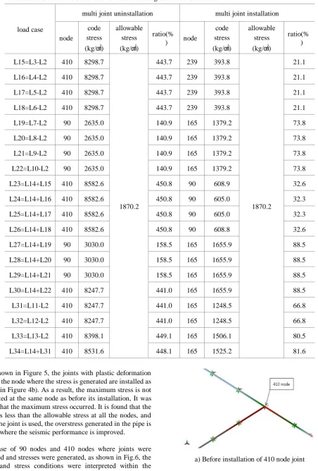
[image:3.595.58.284.596.776.2]Table 4: Maximum Occurrence Stress due to Joint Mounting and Load Conditions
load case
multi joint uninstallation multi joint installation
node
code stress (kg/㎠)
allowable stress (kg/㎠)
ratio(%
) node
code stress (kg/㎠)
allowable stress (kg/㎠)
ratio(% )
L15=L3-L2 410 8298.7
1870.2
443.7 239 393.8
1870.2
21.1
L16=L4-L2 410 8298.7 443.7 239 393.8 21.1
L17=L5-L2 410 8298.7 443.7 239 393.8 21.1
L18=L6-L2 410 8298.7 443.7 239 393.8 21.1
L19=L7-L2 90 2635.0 140.9 165 1379.2 73.8
L20=L8-L2 90 2635.0 140.9 165 1379.2 73.8
L21=L9-L2 90 2635.0 140.9 165 1379.2 73.8
L22=L10-L2 90 2635.0 140.9 165 1379.2 73.8
L23=L14+L15 410 8582.6 450.8 90 608.9 32.6
L24=L14+L16 410 8582.6 450.8 90 605.0 32.3
L25=L14+L17 410 8582.6 450.8 90 605.0 32.3
L26=L14+L18 410 8582.6 450.8 90 608.8 32.6
L27=L14+L19 90 3030.0 158.5 165 1655.9 88.5
L28=L14+L20 90 3030.0 158.5 165 1655.9 88.5
L29=L14+L21 90 3030.0 158.5 165 1655.9 88.5
L30=L14+L22 410 8247.7 441.0 165 1655.9 88.5
L31=L11-L2 410 8247.7 441.0 165 1248.5 66.8
L32=L12-L2 410 8247.7 441.0 165 1248.5 66.8
L33=L13-L2 410 8398.1 449.1 165 1506.1 80.5
L34=L14+L31 410 8531.6 448.1 165 1525.2 81.6
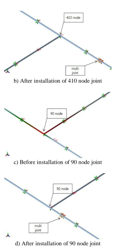
As shown in Figure 5, the joints with plastic deformation around the node where the stress is generated are installed as shown in Figure 4b). As a result, the maximum stress is not generated at the same node as before its installation, It was found that the maximum stress occurred. It is found that the stress is less than the allowable stress at all the nodes, and when the joint is used, the overstress generated in the pipe is solved where the seismic performance is improved.
In case of 90 nodes and 410 nodes where joints were installed and stresses were generated, as shown in Fig.6, the joints and stress conditions were interpreted within the permissible stress range after installation to help improve seismic performance by reducing the stress.
b) After installation of 410 node joint
c) Before installation of 90 node joint
[image:5.595.72.266.39.472.2]d) After installation of 90 node joint
Fig. 6. Stress changes with or without joints that are capable of plastic displacement
IV. CONCLUSION
In this study, the following conclusions were obtained with results of analyzing the seismic safety by applying 0.5g ground acceleration to sprinkler piping and the result of analyzing the seismic safety with plastic displacement joint.
1. It can be seen that the stress generated in the sprinkler piping does not occur constantly in each section of the piping, but it is different depending on the arrangement of the piping in the type of the load case.
2. Analysis of the stress of the sprinkler piping before plastic joints being installed, shows that the stress was mainly generated at the branching point of the piping, and it was found that measures to solve this problem were needed.
3. By comparing the stress analysis values before and after installation of joints capable of plastic displacement, it
occur in almost the same nodes, and the value occurs almost the same even though the load cases are different.
4. It can be seen that the stress is reduced when a joint capable of plastic displacement is installed at the branch of the sprinkler installation pipe where over stress occurs. This is because the joint actively accepts the stress generated in the pipe by the plastic displacement.
In case of earthquake, it can be seen that over stress is generated more than the permissible stress in many part of sprinkler installation piping, which can seriously affect pipe performance. Through this, seismic performance can be improved by applying plastic joints that can analyze the stress of piping and reduce the stress on the problematic nodes in order to design seismic safety for all fire suppression system as well as sprinkler facilities.
ACKNOWLEDGMENT
This research was supported by the Daejeon University Research Grants (2016).
REFERENCES
1. J.O. Lee, H.K. Kim, S.B Cho, “A Study on Performance-based Seismic Design Method of Fire Extinguishing Pipe System,” Fire Science & Engineering, Vol.31. Aug. 2017, pp.86-94.; http://dx.doi.org/10.7731/KIFSE.2017.31.4.086
2. J.O. Lee, D.S. Bang, “A Study on Seismic Design Method Considering Physical Properties of Piping Material,” Fire Science & Engineering, Vol.32. April. 2018, pp.38-47; http://dx.doi.org/10.7731/KIFSE.2018.32.2.038
3. D.M. Lee, “The Seismic Design of Water Extinguishing Piping Systems for Equivalent Static Analysis Method,” Fire Science & Engineering, Vol.26. April. 2012, pp.100-105; http://dx.doi.org/10.7731/KIFSE.2012.26.3.100
4. Y.S. Back, J.S Nam, “A Study on the Seismic Protection Performance of Press Fittings for Light Gauge Stainless Steel Pipes,” Fire Science & Engineering, Vol.31. Aug. 2017, pp.65-70; http://dx.doi.org/10.7731/KIFSE.2017.31.4.065 5. NFPA 13. Standard for the Installation of Sprinkler Systems,
Ch.9; US. NFPA, 2016
6. American Lifelines Alliance. Seismic Design and Retrofit of Piping Systems: US. ASCE, 2002.
7. Ferdinand PB, E. Russell Johnston, David M. Vector Mechanics for Engineers(Statics): US. McGraw-Hill, 2007.
8. Ferdinand PB, E. Russell Johnston, David M. Mechanics of Materials: US. McGraw-Hill, 2015.
9. ASME B31.3. Code for pressure piping: US. ASME, 2014. 10. C.A.E Eng’g S/W. CAESAR Ⅱ Technical Reference Manual:US
C.A.E Eng, 2015.
11. Http://www.USGS.gov/, United States Geological Survey Website, 2019.
AUTHORSPROFILE
Jae-Ou Lee Professor, Department of Fire and Disaster
Ka-Young Oh Master's course students at Daejeon University, Piping seismic analysis, Fire protection
Dae-Seok Bang BNS Joint Co., Ltd. CEO
Joint research and development