International Journal of Innovative Technology and Exploring Engineering (IJITEE) ISSN: 2278-3075, Volume-8, Issue-11, September 2019
Sssc Based Time Delay Compensator Design for
Interconnected Power System
Rama Bharti, Pallavi Bondriya
Abstract – In this paper, researcher designed a delay-dependent wide-area damping controller based on Static Synchronous Series Compensator (SSSC) to enhance the power system stability by using remote signal obtained from Wide-Area Measurement System (WAMS). This remote signals introduces a time delay in the feedback signal, as a result, degrade the system damping performance and even causes instability of close loop power system. To find out various controller parameters, use of Genetic Algorithm (GA) is adopted. The performance of Multi-Machines system is evaluated with proposed controller including signal delay and Conventional PSS(CPSS) in MATLAB simulation. Various results show that SSSC based controller damp-out the inter-area oscillations under small disturbance more effectively as compare to LPSS.
Keywords - Wide-Area Measurement System (WAMS), Power System Stabilizer (PSS), Static Synchronous Series Compensator (SSSC), Genetic Algorithm (GA), Signal delay, Integral of Time Error (ITE).
I.INTRODUCTION
Nowadays, electrical power demand increases continuously, but in that ratio there is no change in infrastructure of power system network to fulfill the demand in different geographical area. Existing power system network should be interconnected so that it can proficiently use separate power resources in separate fields and optimize energy resource distribution. Also, under operating condition if fault or disruption occurs, it can provide additional supporting power of each area of interconnected grids which can make the generation, transmission and distribution system more reliable.The main drawback of an interconnected power system is that, when we interconnect different area of power system network by a tie line which is weak then under some conditions of its operation it developed a inter-area oscillations of low frequency [0.1 Hz – 1 Hz] [1]. If the damping coefficient of the system is not sufficient, then these oscillation leads to loss the system synchronism.
For this, the traditional approach in industry to damp out or diminish inter-area oscillations use CPSS. The fundamental role of LPSS is to increase damping to the oscillation of rotor of the generator by controlling its excitation using Automatic Voltage Regulator (AVR) with auxiliary stabilizing signal [2]. The CPSS use local signal as an input but this type of controller not always able to damp out the inter-area oscillations because local signal based controller do not have global observation [3].
Revised Manuscript Received on September2, 2019.
Pallavi Bondriya,Associate Proffessor & HOD Department of EX,TIT Sciences, Bhopal, MP
In latest years, the development of new wide-area damping controllers to control inter-area oscillations has become a interesting topic with fast advances in synchronized phasor measurement technologies[4-7]. The WPSS has been known to be one of the most efficient solutions to damp out or diminish inter-area oscillations.
Results measured by phasor measuring units (PMUs) are transferred via communication channels to the remote control center in wide-area damping control. Network time delay is therefore inevitable. Such delays vary between tens and several hundred milliseconds. Several studies were conducted to assess the time limit reported in[ 8-10].Since even a very minute delay can result in the stability loss of the power system[11], input delay in controller design can not be overlooked. To control damping in wide-area, the route and mode of transmitted signal will also be corrected as soon as the place to be controlled and signal for feedback is chosen. Usually, in the short term, this transmission path will not alter, so that the delay in WPSS input will be stable. The signal delay given can therefore be designed as a steady delay in the layout of the controller. Smith predictor[25] and Pade approximation[22] are two efficient approaches to addressing this type of issue of constant time delay. This document is about the approximation of Pade. A dedicated communication channel generally offers in any transmission condition no more than 50 ms delay[18].
However, electronic energy systems are currently being created. With improved dynamic efficiency, they are more efficient in raising the quantity of transmitted energy and more accurate in controlling the power flow path. The implementation of FACTS in power systems is used in these techniques.
Engineer's recently used FACTS controllers for the applications in the power system. The primary goal of the FACTS device used is to regulate parameter of the system at a very fast pace so that the stability of the system is improved [15 ].The SSSC is regarded a FACTS family member. One of distinctive ability to switch from capacitive characteristic to inductive is shown by SSSC [16]. This uses an additional signal that stabilizes and can considerably improve the system's stability. Basically, the SSSC control function is done by this auxiliary signal [17]. The implementation of SSSC is addressed in[ 19–23] to enhance stability and dampen system oscillation.
4118
Published By:
Blue Eyes Intelligence Engineering & Sciences Publication
Retrieval NumberK19210981119/2019©BEIESP DOI: 10.35940/ijitee.K1921.0881119
Moreover, in this paper, a simple SSSC based controller designed based on change in speed deviation as a input signal.
The key factor for control system design is its robustness. In order to design robust controller to damped out inter area oscillations parametrs of controller are optimized by Genetic Algorithm (GA) based on Time Error Integral(ITE). This paper is broken down into five parts. The first chapter is the introduction to the issue because of inter-area oscillations and signal delay. Section II represents the configuration of the study power system with SSSC and PSS. Section III presents the design of the proposed controller. In addition, the PSS optimization process parameters for achieving better GA-based efficiency and robustness. Section IV demonstrates the controller's simulation outcomes and the outcomes of the comparison. Finally, the conclusions in chapter V are finished.
II.STUDYPOWERSYSTEM
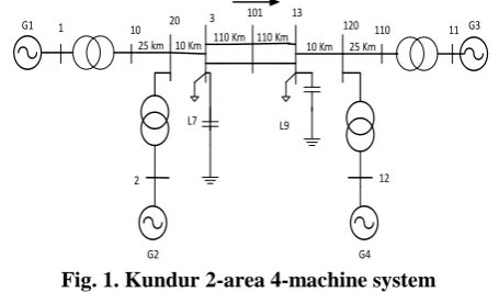
System under this research work is shown in figure-1. It consists of two similar symmetrical areas inter linked by two parallel tie-line of length 220 Km and 230 kV. Each area has two generators of rating 20 kV/900 MVA both having identical round rotor. All four generators have identical parameters, except inertia coefficient (H), which are for Gen-1 and Gen-2 in area-1 and for Gen-3 and Gen-4 in area-2 [2].
1
2 12
11 10 20 3
101 13
120 110 25 km 10 Km 110 Km 10 Km 25 Km G1
G2 G4
G3
L7 L9
413MW
[image:2.595.321.531.51.136.2]110 Km
Fig. 1. Kundur 2-area 4-machine system
III.THEPROPOSEDCONTROLMETHOD (a)Controller design considering time delay with SSSC
and LPSS
Figure-2 demonstrates the damping controller design that is used by the SSSC to regulate the voltage input (Vq). The variation in G-2 and G-4 speed deviation (availability) is regarded as the controller's input and Vq is regarded the controller's output. Four blocks are considered here in the damping controller design[22], namely signal delay block with pade approximation, gain block with Kstab gain, determines how much damping the PSS has introduced. A high-pass washout filter with moment constant parameter TW, eliminating the low frequencies current in the speed signal and the PSS is allowed to react only to speed changes else no reaction and in Figure. 2 a 2-stage block of phase compensation is shown. The washout block will work as a filter which allows only high frequencies to pass and the phase compensation block will provide the appropriate phase-leading characteristics with time constants T1, T2, T3 and T4.
Fig2. Block diagram of SSSC based damping controller (b)Pade Approximation
The wide-area controller's feedback signal delay the control impact is affected by the delay will introduce input signal phase deviation. In f frequency oscillation mode, the phase lag which is introduced by delay( can be obtained by :
For instance, if a WPSS ' dominant frequency is 0.6 Hz, a 100 ms delay will introduce a [ 23 ] phase lag.
(Phase lag)
From above, it can be observed that both the frequency of oscillation and the delay itself determine the phase lag introduced by delay. The associated phase lag with the greater frequency is bigger for the same delay, and vice versa.
In MATLAB, the exponential shape ( ) of the Laplace domain expresses time-delays. It can be substituted by a Pade approximation of first order[24 ].
In this work, 50 ms time-delay is taken only.
[image:2.595.55.283.392.525.2]International Journal of Innovative Technology and Exploring Engineering (IJITEE) ISSN: 2278-3075, Volume-8, Issue-11, September 2019
Start
Randomly initialize N number of population
Evaluate fitness of each individual
Roulette wheel selection
Crossover
Mutation with certain probality
New population
Meeting end of criterion?
Return best solution NO
[image:3.595.61.281.48.375.2]YES
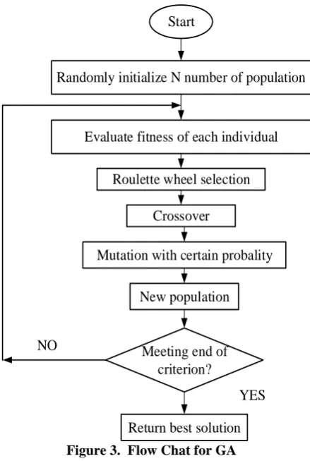
Figure 3. Flow Chat for GA
A set of alternatives called the population (represented by chromosomes) begins the genetic algorithm. results are drawn from one population and outcomes are used to create a fresh population. This motive is due to the likelihood of bettering the fresh population compared to old. Solutions are selected to form fresh solutions (offspring) as per their fitness; they are high/more appropriate, there is high/more likely to reproduce. This process is continously repeated until some condition (e.g improvement of the best solution) is satisfied.
Oscillation of a system can be seen through the active power deviation tie-line or rotor speed deviation. Research is aimed at minimizing the oscillation of any deviation. The integral of time error of speed deviation forG-2and G-4 is taken as an objective function (J) for kundur's 2-area 4- machine scheme.
where
simulation time range.
The simulation of the time domain of the above power system is performed for a specified period of time and the calculation for the the objective function of the simulation is done. The PSS and damping controller prescribed range is restricted within a border. From the above design approach, the following optimization problem is formulated.
Minimize J
Subject to :
where and are the min and max bound of time constant for the controllers. All four time constants have same range of lower and upper limits: 0.01 to 1.
IV.SIMULATION RESULTS OF PROPOSED CONTROLLER
1
2 12
11 10 20 3
101 13
120 110 25 km 10 Km 110 Km 10 Km 25 Km G1
G2 G4
G3
L7 L9 413MW
SSSC
Controller
PMU PMU
dw2 dw4 110 Km
Fig 4. 2-area 4-machine interconnected power system with a SSSC connected in series with the transmission
line
The structure of a power system with the proposed controller used in this research is shown in Figure 4. SSSC is mounted between B-101and B-13 in series with the transmission line. To assess the difference in speed between two inter-area oscillation generators, two PMUs are installed at G-2andG-4 respectively for wide-area control. The control system for the proposed design includes 50 ms delay time owing to wide-area control communication system.
[image:3.595.328.531.137.281.2]For this study, value of the controller gain is taken as K=101.0779[25] and other parameters of the suggested controller after optimizing GA based on the ITE criteria set out in Table – I.
Table – 1 Optimized Controller Parameters Using GA T1 (S) T2 (S) T3 (S) T4 (S) Damping Controller
(with out delay) 0.9067 0.9142 0.1066 0.5514
Damping Controller
(50ms delay) 0.1706 0.1156 0.8545 0.7824
4120
Published By:
Blue Eyes Intelligence Engineering & Sciences Publication
[image:4.595.312.545.44.588.2]Retrieval NumberK19210981119/2019©BEIESP DOI: 10.35940/ijitee.K1921.0881119
[image:4.595.56.285.51.750.2]Figure 5. Different parameters of power system without controller
[image:4.595.64.276.51.174.2]Figure 6: Tie-Line Active Power Flow
Figure 7: Speed deviation of G-2 w.r.t. G-1
Figure 8: Speed deviation of G-3 w.r.t. G-1
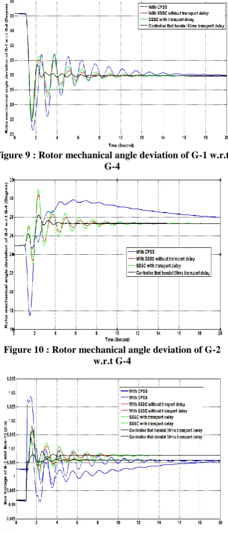
Figure 9 : Rotor mechanical angle deviation of G-1 w.r.t G-4
Figure 10 : Rotor mechanical angle deviation of G-2 w.r.t G-4
Figure 11 : Bus voltage at B-3 and B-13 (p.u)
VI.CONCLUSION
[image:4.595.50.284.407.737.2]International Journal of Innovative Technology and Exploring Engineering (IJITEE) ISSN: 2278-3075, Volume-8, Issue-11, September 2019
REFERENCES
1. Pal, B.C. “Robust Damping Control of Inter-Area Oscillations in Power System with Super-conducting Magnetic Energy Storage Devices ,” PhD thesis, Imperial college of Science Technology and Medicine, Department of Electrical & Electronics Engineering. 2. Kundur P. Power system stability and control. New York: Mc-Grall
Hill; 1994.
3. Zhang P., Messina A. R, Coonick A., and Cory B. J., “Selection of locations and input signals for multiple SVC damping controllers in large scale power systems,” in Proc. IEEE Power Eng. Soc. Winter Meeting,1998, pp. 667–670.
4. J. D. L. Ree, V. Centeno, J. S. Thorp, and A. G. Phadke, “Synchronized phasor measurement applications in power systems,” IEEE Trans. Smart Grid, vol. 1, no. 1, pp. 20–27, Jun. 2010.
5. I. Kamwa, R. Grondin, and Y. Hebert, “Wide-area measurement based stabilizing control of large power system—A decentralized/hierarchical approach,” IEEE Trans. Power Syst., vol. 16, no. 1, pp. 136–152, Feb. 2001.
6. H. Ni, G. T. Heydt, and L. Mili, “Power system stability agents using robust wide area control,” IEEE Trans. Power Syst., vol. 17, no. 4, pp. 1123–1131, Nov. 2002
7. B. Naduvathuparambi, M. C. Valenti, and A. Feliachi, “Communication delays in wide area measurement systems,” in Proc. 34th Southeastern Symp. Syst. Theory, 2002, pp. 136–153.
8. C. W. Taylor, V. Venkatasubramanian, and Y. H. Chen, “Wide-area stability and voltage control,” in Proc. 7th Symp. Spec. Elect. Oper. Expansion Plan., Curitiba, Brazil, May 2000, pp. 1–9.
9. J. W. Stahlhut, J. Browne, G. T. Heydt, and V. Vittal, “Latency viewed as a stochastic process,” IEEE Trans. Power Syst., vol. 23, no. 1, pp. 84–91, Feb. 2008.
10. A. F. Snyder et al., “Interarea oscillation damping with power system stabilizers and synchronized phasor measurements,” in Proc. Int. Conf. Power Syst. Technol. (POWERCON), Beijing, China, Aug. 1998, pp. 790–794.
11. D. Philipp, A. Mahmood, and B. L. Philipp, “An improved refinable rational approximation to the ideal time delay,” IEEE Trans. Circuits Syst. I, Fundam. Theory Appl., vol. 2, no. 5, pp. 637–640, May 1999. 12. Hingorani NG, Gyugyi L. Understanding FACTS: concepts and
technology of flexible AC transmission systems. New York: IEEE Press; 2000.
13. Panda S. Multi-objective evolutionary algorithm for SSSC-based controller design. Electr Power Syst Res 2009;79:937–44.
14. Mihalic R, Papic I. Static synchronous series compensator – a mean for dynamic power flow control in electric power systems. Electr Power Syst Res 1998;45:65–72.
15. Panda S, Swain SC, Rautray PK, Mallik R, Panda G. Design and analysis of SSSC based supplementary damping controller. Simulat Model Pract Theor 2010;18:1199–213.
16. Wang HF. Static synchronous series compensator to damp power system oscillations. Electr Power Syst Res 2000;54:113–9.
17. Gyugyi L, Schauder CD, Sen KK. Static synchronous series compensator: a solidstate approach to the series compensation of transmission lines. IEEE Trans Power Del 1997;12:406–17.
18. Panda S. Design and analysis of SSSC-based supplementary damping controller. Simul Model Pract Theor 2010;18:1199–213.
19. Khadanga RK, Sata pathy JK. Gravitational search algorithm for the static synchronous series compensator based damping controller design. IEEE Tech Sym 2014;356:361.
20. Ray S, Venayaga moorthy GK, Watanabe EH. A computational approach to optimal damping controller design for a GCSC. IEEE Trans Power Del 2008;23: 1673–81
21. Lin Cheng,Gang Chen, Wenzhong GaoFang Zhang and Gan Li, “Adaptive Time Delay Compensator (ATDC) Design for Wide-Area Power System Stabilizer” IEEE TRANSACTIONS ON SMART GRID, 2014.
22. L. D. Philipp. Ausif Mahmood, B. L. Philipp, “An improved refinable rational approximation to the ideal time delay,” IEEE Trans. Circuits and Systems, vol. 46, pp. 637-640, May 1999.
23. Mahran A. R., B. Hogg W., and El-Sayed M. L., Coordinated Control of Synchronous Generator Excitation and Static VAR Compensator, IEEE Trans. Energy Conversion, 7(4): 615--622, December 1992. 24. Khadanga RK, Satapathy JK, “Time delay approach for PSS and SSSC
based coordinated controller design using hybrid PSO–GSA algorithm” Elsevier, March, 2015 Electrical Power and Energy Systems 71 (2015): 262–273.
25. R. Majumder, B. Chaudhuri, B. Pal, and Q.-C. Zhong, “A unified Smith predictor approach for power system damping control design using remote signals,” IEEE Trans. Control Syst. Technol., vol. 13, no. 6, pp. 1063–1068, Nov. 2005.
26. M. E. Aboul-Ela, A. A. Sallam, J. D. McCalley, and A. A. Fouad, “Damping controller design for power system oscillations using global signals,” IEEE Trans. Power Syst., vol. 11, no. 2, pp. 767–773, May 1996.
AUTHORSPROFILE
Pallavi Bondriya, Associate Proffessor &HOD Department of EX,TIT Sciences,BHOPAL,MP
Rama Bharti