Bit Error Rate Reduction Using Index
Modulation in MIMO OFDM System
Mohammad Azim 1, Dr.Rajesh S. Bansode2
P.G. Student, Department of Electronics and Telecommunication Engineering,Thakur college of Engineering and
Technology, Mumbai, Maharashtra, India1
Professor, Department of Information Technology,Thakur college of Engineering and Technology, Mumbai,
Maharashtra, India2
ABSTRACT:The frequency spectrum is an expensive resource limiting the bandwidth. To achieve high speed (10-6), data rate (1Gbps) and simultaneous increase in range and reliability without consuming extra radio frequency (3 KHz-300GHz) requires enhanced spectral efficiency in order to increase link throughput, to meet QOS, and network capacity. So to fulfil these requirements the MIMO-OFDM system for wireless broadband communication is used.
In wireless transmission, bit error rate detoriates over wireless transmission, the reductionof a data channel andthe corresponding (BER) bit error rate is noise and changes to thepropagation path. In OFDM transmissions system a term called peak-to-average power ratio(PAPR), arises which result in corresponding distortion when signal gets transmitted through a nonlinear nature device, such as a power amplifier use at transmitter stage.
The limitations of OFDM signals are that, the OFDM signals are more immune to the time-varying channel, which breaks the orthogonally between sub-carriers, causes the generation of inter-channel interference (ICI).It is seen that once the symbols are transmitted in the radio fading channel, then the transmitted signal will suffer deep fades that give rise to loss of signal or outage of signal.
Outage probability is a performance measure of MIMO system. The outage probability is a measure of the quality of the transmission in a mobile radio channel. Outage arises when the received signals goes below a given threshold level. Like (0.1% or 0.5%).There is criteria to increase the BER beyond 10-5 using 8X8 MIMO system or higher, to achieve the data rate of 1Gbps..To improve all these parameters, a orthogonal frequency division multiplexing with index modulation (OFDM-IM) technique is used for frequency selective fading channels. The information is conveyed not only by M-ary signal constellations as in classical OFDM, but also by the indices of the subcarriers, which are activated according to the incoming bit stream.
The paper deals with measurement/analysis of parameters such as BER, SNR, outage capacity, for (4X4,8X8) MIMO system using QPSK,16-QAM, to improve BER beyond 10-5. It is observed via computer simulations that the proposed MIMO-OFDM-IM scheme achieves significantly better error performance up to 10-5 than classical MIMO-OFDM using QPSK, 16-QAM for several (2X2,4X4,8X8) system configurations due to the information bits carried in the spatial domain by the indices of OFDM subcarriers.
KEYWORDS: BER, ICI , MIMO, OFDM, OFDM-IM ,PAPR, QAM, QPSK , SIM, SNR.
I. INTRODUCTION
MIMO is abbreviated to multiple input multiple output system, uses multiple Tx and Rx antenna to multiply the capacity
of a radio link.The power efficiency of MIMO system can be increased by maximizing spatial diversity. Such techniques are STBC and STTC.Another technique is V-BLASTused to increase the channel capacity.
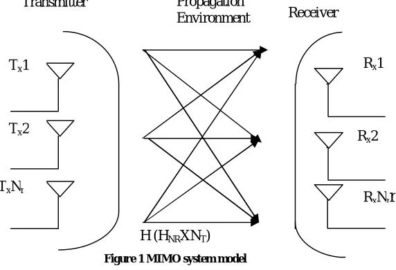
High BER, low SNR,wireless systems like SISO, SIMO and MISO fails to meet the growing demands of users. Therefore a new technique MIMO is used.The MIMO system is used to improve spectral efficiency, data rate, and transmission coverage, to minimize error,to optimize speed, without wasting the additional frequency spectrum.[1] Consider a transmitter with N transmits antennas, and a receiver with M receives antennas.
The channel can be modelled by the NXM matrix H, where H is the channel matrix, the NX1 received signal y is given by Eq.1
y=Hs+n (1)
Where s is the transmitted symbol (s1, s2, s3…SNT),and the covariance matrix for this transmitted signal is given by Eq.2
Rss= INT (2)
Where is equal to the power of each antenna. In the formula (1), the Hcan be defined as given byEq.3
H=
⎣ ⎢ ⎢
⎡hh h . . . hh . . . h . .
hN1 hN2 hNM⎦ ⎥ ⎥ ⎤
(3)
Herehij is a term calledcomplex Gaussian random variable that is used to models fading gain between the Jth transmit
antenna and Ith receive antenna in MIMO system.
H (HNRXNT)
Figure 1 MIMO system model
The generalize model of MIMO as shown in fig.1. At first, the incoming data streams travels through serial to parallel converter and then all the streams are modulated by using BPSK,QPSK,16 QAM modulation technique. etc.
At receiver end, the modulated data stream is collected and then demodulated and detected by the V-BLAST detection technique.[2]
MIMO the only efficient way to increase bandwidth, range & will become a core technology in wireless systems. The MIMO channel is constructed with multiple antennas at both ends of the wireless link.[3]
The layout of the paper is as follows. section 1 describes about MIMO, section 2 depicts about the modulation technique, section 3 explains the system model, section 4 describes about implementation of OFDM-IM, section 5 explains principle of index modulation and operation of MIMO OFDM-IM system, section 6 summarizessimulation results and section 7 states the conclusion of the paper.
Transmitter
Receiver Propagation
Environment
Rx1
Rx2
RxNr
r
Tx1
Tx2
2
II. MODULATIONTECHNIQUES
The process of varying property of carrier signal, with a modulating signal that typically contains information to be transmitted. This alteration is termed modulation, and it's the modulated signal that's transmitted. The receiver then recovers the initial signal through a method known as demodulation.Modulation is the way in which the information is superimposed on the radio carrier.Modulation techniques must have varieties of properties such as.[4]
a. Good Bit Error Rate Performance: BER is the percentage of
bits
with errors divided by the total number of bits that have been transmitted, received or processed over a given time period. The rate is typically expressed as 10 to the negative power. Low bit error rate is required in the presence of fading, Doppler spread effect in wireless system.b. Power Efficiency: Power limitation is one of the critical design challenges in mobile applications. Nonlinear amplifiers are usually used to increase power efficiency. However, nonlinearitypresent at the amplifier output cause degradation to the BER performance of modulation.
c. Spectral Efficiency: It refers to the information rate that can be transmitted over a given bandwidth in a specific communication system. Spectral efficiency density should have a narrow main lobe and fast roll-off of side lobes. It is defined as η =bitspersec/channel B.W[4]
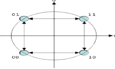
A. Quadrature Phase shift Keying
Here, the phase of the carrier signal is divided which is designed by allotting four equally spaced values for the phase angle.QPSK sent twice data that can be sent in the same bandwidth compared to BPSK.QPSK provides twice the spectral efficiency with same energy efficiency. QPSK has four constellation points in the constellation diagram. But the exact phase retrieval is a challenge in the receiver design considerations, failing which can give rise to erroneous detection of the signal. This factor increases the receiver design complexities. To overcome these problems, and to shape up the carrier modulated signal, the root raise cosine pulse shaping is used, which in turn provides demerits that the constant envelope property of the signal is lost.[4]
Figure 2 Constellation diagram for QPSK
The implementation of QPSK is more general than that of BPSK as given byEq.4
Sn(t)= Cos(2πfct) +π(2n−1), where n = 1,2,3,4 (4)
This yields the four phase’s π/4, 3π/4, 5π/4 and 7π/4 as needed. This results in a two-dimensional signal space with unit basis function. The first basis function is used as the in-phase component of the signal, is given by Eq.5,
Φ1(t)= Cos(2πfct), (5)
And second basis function is used as the quadrature component of the signal, is given by Eq. 6
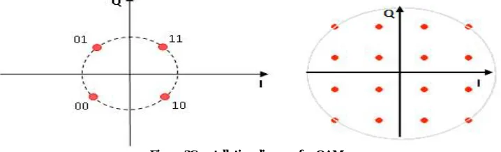
B. Quadrature amplitude modulation
Quadrature amplitude modulation (QAM) requires changing the phase and amplitude of a carrier sine wave. 16-QAM is also called 16-state quadrature amplitude modulation.Here four I phase values and four Q phase values are used, which generates four bits per symbol.It has 16 states because 24 = 16.Its theoretical bandwidth efficiency is four.let’s look at the time domain representation of QAM signals. Taking 4 QAM, supposed to transmit the bitstream 100111.Map the to 4-QAM symbols representing 10, 01, 11. The time domain waveform for this bit stream is shown in
Figure 3Constellation diagram for QAM
Figure 3.One period of the sine wave has a unique phase shift. In this respect, 4 QAM might be considered a special case of QAM where the amplitude is the same for all symbols. [4]
a. Bit Error Rate (BER):
The Bit error rate is a ratio of number of bits received in error divided by the number of transmitted bits, measure in dB, as given by Eq.7
BER= (Bits in Error) / (Total bits received) (7)
In wirelesstransmission, when the number of data bits is received, and if these data bits has modified compare to transmitted data bits, so this happens due quantization, and synchronization error. BER is often expressed as normalized carrier-to-noise ratio measured denoted Eb/N0 that is energy permit to noise power spectral density
ratio.[4]
b. Signal to noise to ratio:
The SNR is the ratio of the received signal power over the noise power in thefrequency range of the process, and measured in decibel (dB). SNR is inversely related to bit error rate.High BERcauses an increase in packet loss, enhance in delay and decrease throughput,and is given by Eq.8.[4]
SNR = 10 log10 (Signal power / Noise power) dB (8)
III.RELATEDWORK
In OFDM-Index modulation system, a frequency-selective Rayleigh fading channel is considered for transmission. A total of minformation bits are entered to the OFDM-IM transmitter for the transmission of each OFDM block. Each group of m information bits are then split into g groups,each group contains p bits. i.e., m = pg. Each group of p bits is mapped to an OFDM sub block of length n where n = N/g and N -number of OFDM subcarriers. This symbols mapping operation is not only performed by means of modulated symbols as in classical MIMO-OFDM but also by the indices of the subcarriers. For each sub-block, only k out of n available indices are employed and they are determined by using a selection procedure. For the selection procedure two different mapping methods are used.
First, let us use a simple,Look-up table method which indicates active indices for corresponding active bits. In case of having large number of information bits to be transmitted, the use of a look-up table becomes infeasible.
Then a simple and effective technique which is based combinatorial number theory to map the m information bits to the subcarrier indices. The symbols selections corresponding to sub career is performed as follows,
The symbols are set to zero corresponding to inactive subcarrier, and data is not transmitted with inactive subcarrier. The remaining p2 = k log2 M bits of this sequence are mapped onto M-ary signal constellation, so that by Eq.9,
So it is observed that the information is conveyed by both ofthe M-ary signal constellation symbols and the indices of the subcarriers which are modulated by these constellation symbols.The loss in the total number of bits to be transmitted can be compensated by transmitting additional bits in the index domain of the OFDM block.For each OFDM sub blockβ,the incoming bits are transferred to the index selector,this block chooses k,active indices out of n available indices , the selected indices are given by Eq.10,
IB={i,β,1,…..iβ,k}, (10)
Where iβ,γ[1,….,n] for β=1,…..,g and γ=1,….,k.
The vector of the modulated symbols at the output of the M-ary mapper is given by Eq.11
Sβ=[ Sβ(1),….., Sβ(k)], (11)
The Block called OFDM block creator generates all of the sub blocks and it then forms N x 1 main OFDM block, is given by Eq.12,
XF=[x(1)x(2),….x(N)]T (12)
After this, the same procedures of the classical OFDM are applied. The OFDM block is processed by the inverse FFT (IFFT) algorithm, is given by Eq.13
XT=√ IFFT{ XF}=√ WNH XF (13)
Where XT is the time domain OFDM block, WN is the discrete fourier transform (DFT) matrix with WNH WN=NIN and
the term
√ is used for the normalization.[5]
IV.METHODOLOGY
This section particularly deals with development of index selector and index demapper block. The index selector maps the incoming information bits to a group of active indices out of C (n; k), possible candidates, whereas the index demapper provides estimates of these bits by processing the detected active indices. Instead of dealing with a single OFDM block with higher dimensions, the OFDM block is estimated into smaller sub-blocks to ease the index selection and detection processes at the transmitter and receiver respectively. ML or LLR detectors are used employed for this purpose.
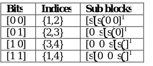
A. Lookup table method:
A look-up table 1 is created having size c to be used at both transmitter and receiver side. At the transmitter stage, the look-up table gives the indices for corresponding incoming p1 bits for each sub block, and it performs the opposite operation at the receiver. A look-up table for n = 4, k = 2, and c = 4 is shown in table 1. Where Sϰ,Sξϵ s. Since C (4, 2) = 6, two combinations out of six are discarded. This method is efficient and simple for smaller c values; this mapping method is not feasible for higher values of n and k due to the size of the table. Generally this method is used with the ML detector at receiver, since the receiver has to know the set of possible indices for ML decoding, i.e., it requires a look-up table.
Table 1 Reference look-up table for N=4, K=2, p1=2
On the other hand, a look-up tabledoes not use with the LLR detector at receiver since the receiver cannot decide on active indices if the detected indices do not exist in the table 1.[5]
B. Combinational method:
The combinational number system actually performs a one-to-one mapping between natural numbers and k combinations, for all n and k. (i.e.) it maps a natural number to a strictly decreasing sequence, as given by Eq. 14
J={ck,……,c1},ck>... c1≥ 0, (14)
In other words, forfixed n and k, all Z can be presented by a sequence J of length k, which takes elements from the set {0,….,n-1},in accordance with the following Eq.15
Z=C(ck,k)+…+ C(c2,2)+ C(c1,1) (15)
An example for n = 8, k = 4, C (8, 4) = 70, the following J sequences can be calculated as, shown in table 2.
The algorithm, which finds the lexicographic ordered J sequences for all n, can be explained as follows: start by choosing the maximal ck that satisfies C (cK, k) ≤z,and then choose the maximal ck-1 that satisfies Eq.16
C(cK-1;k-1) ≤z-C(cK,k) (16)
In this scheme, for each symbols sub block, the p1 bits entering the index selector are converted to a decimal number Z, and then feed this decimal number to the combinatorial algorithm to select the active indices as J + 1.At the receiver
side, after determining active indices, we can easily get back to the decimal number ^Z using (15). We then apply this number to a p1-bit decimal-to-binary converter. This method is used with the LLR detector for higher c values to avoid
Table 2 J’s sequence calculations
look-up table. However, it can give a catastrophic result at the exit of the decimal-to-binary converter if ^ Z≥C we use this detector for the increased bit-rate. In order to improve the data rate beyondthe 10-6, the new technique called MIMO OFDM with index modulation can be adopted.[5]
V. EXPERIMENTALRESULTS
A. MIMO-OFDM using higher modulation techniques:
In this section, the analysis of MIMO OFDM 08X08, 16X16 MIMO system using QPSK and 16-QAM modulation under Rayleigh fading channel is considered. This system is built with the following parameters. convolution encoding and ML detection is used at receiver.
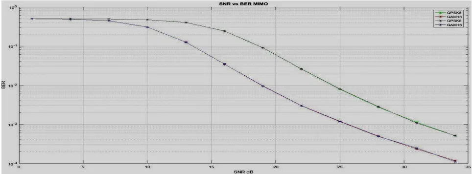
Figure 4 BER vs. SNR graph for 16X16,32X32 MIMO using QPSK,16-QAM
Considering 8X8 MIMO system the BER difference of 6.8dB is obtained between QPSK, 16-QAM modulation. Considering the 16X16 MIMO BER difference of 7.8 dB is obtained between QPSK, 16-QAM modulation.The BER vs. SNR graph for
08X08,16X16 MIMO using QPSK,16-QAM is shown in fig.4.The graph shows that16-QAM provide improvement in the bit error rate compare to the QPSK technique. Here data rate can beincreased beyond 10-6 using higher order M-QAM such as 256-QAM and using the MIMO OFDM with IM.
B. MIMO-OFDM with Index modulation: a. Case1:
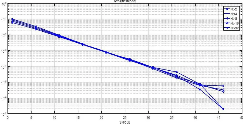
The implementation of MIMO-OFDM-IM is done here, the following parameters are considered whileimplementation. N=64(one OFDM symbol),(n-available symbols=16),(K-selected symbols=8),2X2,4X4, 8X8, 16X16, 32X32 MIMO configurations.No. ofsymbols=64000, Here, the OFDM-IM system is built with the SIM modulation and demodulationconcept to transmit the information symbols. The BER vs.SNR graph for2, 4, 8, 16, 32 MIMOconfigurations is shown in fig.5.The table 3 shows the BER performance analysisresultfor2, 4, 8, 16, 32MIMO configuration using SIM modulation and demodulation.[5],[6]
Figure 5BER vs. SNR analysis for various MIMO systems using index modulation
Table 3 BER vs. SNR analysis for various MIMO systems using index modulation
Reported results Obtained results
Order of MIMO BER SNR
(dB)
Order of MIMO BER SNR
(dB)
SNR Difference (dB)
NT=2 10-5 42 NT=2 10-5 37.8 4.2
10-6 47 10-6 41 6
NT=4 10-5 45.4 NT=4 10-5 38.2 7.2
10-6 45.7 10-6 42.5 3.2
NT=8 10-5 45.8 NT=8 10-5 38.7 7.1
10-6 49.2 10-6 46.5 3.7
NT=16 10-5 - NT=16 10-5 39.2 -
10-6 - 10-6 46.9 -
NT=32 10-5 - NT=32 10-5 39. -
10-6 - 10-6 47 -
QPSK is obtained with respectto results in reported papers. b. Case 2:
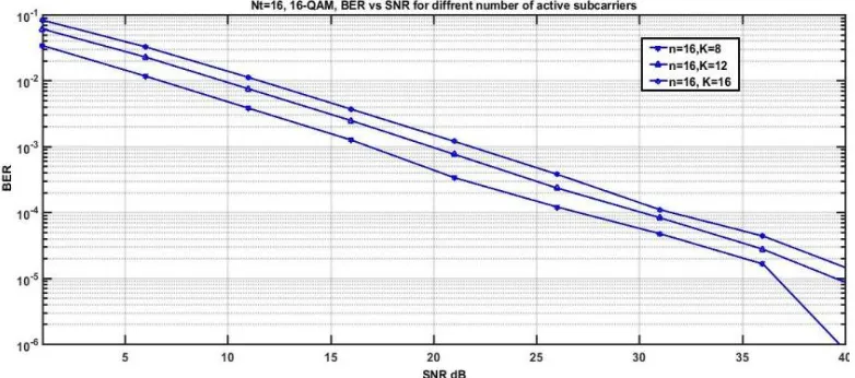
The implementation of MIMO-OFDM-IM is done here.The main focus here is to use the constant value of (n-available subcarrier-16)and variable values for the ‘k’(k-selected subcarrier=8,12,16) to implement the BER vs.SNR graph for MIMO system implementedusing the index modulation as shown in fig. 6.The following parameters are considered while implementation.(N-one OFDM symbol)=64,(n-available subcarrier)=16,(k- selected subcarrier=8, 12, 16), NT=16,NR=NT,M1-QPSK=4,M2=16-16-QAM,no.of symbol=40000, modulation=16-QAM.Thetable 4 shows the BER
vs. SNR result for differentnumber of active subcarrier (k=8, 12, 16) with NT =16, 16-QAM. [5], [6]
Figure6 BER vs. SNR Graph for NT =16, 16-QAM, for different number of active subcarrier
Table 4NT =16, 16-QAM, BER vs. SNR for different number of active subcarrier
Reported results Obtained results
MIMO parameters BER SNR
(dB)
MIMO parameters BER SNR
(dB)
SNR Difference
(dB) (n=16,
k=8)
10-4 31 (n=16,
k=8)
10-4 26 5
10-5 41 10-5 37 4
(n=16, k=12)
10-4 33.6 (n=16,
k=12)
10-4 30 3.6
10-5 43.5 10-5 40 3.5
(n=16, k=16)
10-4 32.3 (n=16,
k=16)
10-4 31.5 0.8
c. Case 3:
The implementation of MIMO-OFDM-IM is done here.
Figure 7 BER vs. SNR Graph for BER vs. SNR for variable values of ‘M(QPSK)=4, 16(16-QAM’
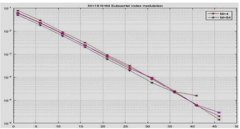
Figure 8 BER vs. SNR Graph for variable values of ‘M(QPSK)=4, 64(64-QAM’
The main focus here is to use the constant value of(NT-transmit antenna=16) and variable values for the
‘M’(M-QPSK=4, 16-16-QAM, 64-64-QAM), to implement the BER vs. SNR graph for MIMO systemimplemented using the index modulation as shownin fig.7 and fig. 8.The following parameters are consideredwhile implementation. (N-one OFDM symbol=64,)(N-available carrier=16), (k-selected carrier)=8,NT=16,NR=NT, M= (04,16,64),
no.ofsymbols=64000,modulation=16-QAM.The table 5 shows the BER vs. SNR result for different size of M (M=4, 16) with NT =16, 16-QAM.From theabove results tabulated intable 5, the SNR difference (OFDM-IM, QPSK= (5.2, 1 dB), and (OFDM-IM, 16-QAM= (0.4,-2 dB). [5],[6]
VI.CONCLUSION
The recently proposed MIMO-OFDM-IM scheme has been investigated for next generation 5G wireless networks. A novel OFDM scheme, which uses the indices of the active subcarriers to transmit data, has been analysed in this paper using series of MATLAB simulation. In this this scheme, the coming information bits are transmitted in a unique fashion to improve the bit error rate performance as well as to increase spectral efficiency.
The considered OFDM system parameters are given as follows: NF = 512, subcarrier spacing Δf= 15 kHz, sampling frequency fs= 7.68 MHz, CP= 36 and L =10.
Thus the theoretical as well as MATLAB simulation results for the MIMO-OFDM-IM scheme have been analysed and its comparisons are made with the classical MIMOOFDM scheme for different type of detectors and system configurations. Thus from this analysis it has been concluded that the MIMO-OFDM-IM scheme outperform better compare to the classical OFDM system in terms of bit error rate performance, outage capacity, ergodic capacity.
Using 2X2 MIMO the BER difference of 4.5dB is obtained between QPSK, 16-QAM modulation. Considering the 4X4 MIMO BER difference of 5.2dB is obtained between QPSK, 16-QAM modulation. Considering 8X8 MIMO the BER difference of 6.8dB is obtained between QPSK, 16-QAM modulation. Considering the 16X16 MIMO BER difference of 7.8dB is obtained between QPSK, 16-QAM modulation.
Secondly when the MIMO-OFDM-IM system is built with the subcarrier index modulation. So the difference in BER of 1dB is obtained by employing the 16x16 MIMO, QPSK, 16-QAM technique modulation. It is seen that the OFDM-IM system has achieved better BER compared to classical MOFDM-IMO-OFDM system.
It is seen that the proposed scheme achieves significantly better BER (i.e-10-5 at SNR=30dB) performance than classical MIMO-OFDM system using QPSK, and 16-QAM under different MIMO configuration.
For the MIMO-OFDM-IM scheme, ML detector has been used. To improve performance parameters such as BER, new detectors such as near-ML, simple MMSE, MMSE-LLR-OSIC detectors can be used. As future research, can be done on OFDM-IM system with the implementation of different transceiver structures to increase the data rate as well as to improve the error performance. The proposed scheme should also be investigated in real world conditions such as mobility. (i.e. zero mobility, high mobility).
Size of M
Modulation technique
BER SNR
(dB) Size of M Modulation technique BE R SNR (dB) SNR Difference (dB)
4 QPSK
(4x4)
10-4 25 4 16-QAM 10-4 30.2 SNR diff1=5.2
10-5 35 10-5 36 SNR diff2=1
16 16-QAM 10-4 30 16 16-QAM 10-4 29.6 SNR diff1=-0.4
10-5 40 10-5 38 SNR diff2=-2
64 16-QAM 10-4 -- 64 16-QAM 10-4 27 ----
REFERENCES
[1] R. Bansode, P.Sarode, B. K. Mishra, “Design, simulation and Performance Evaluation of 4 x 4 MIMO Transceiver System using 16 QAM,”
International Journal of Applied Information Systems (IJAIS,), ISSN: 2249-0868, pp.28-38, 2013.
[2] R.ahmad, D.P.singh, M.singh, “Ergodic Capacity of MIMO Channel in Multipath Fading Environment,” I.J. Information Engineering and
Electronic Business, vol.3,pp.41-48,march,2013.
[3] E. Başar, “Multiple-Input Multiple-Output OFDM with Index Modulation, “International IEEE Signal Processing Letters, ISSN: 1070-9908, vol.22, no12, pp. 2259 - 2263, Oct. 2015.
[4] S.Kumari, R.Bera, S.Dhar, “Modeling and Analyzing the BER Performance of MIMO System using different Modulation Technique,”
International Journal of Engineering Research & Technology (IJERT), ISSN: 2278-0181, pp.505-510, vol. 4 issue 05, May-2015.
[5] [5] E.Başar, “Orthogonal frequency division multiplexing with index modulation,” International GlobalCommunications Conference
(GLOBECOM), ISSN: 1930-529X, pp.4741-4746, Dec. 2012.