Rochester Institute of Technology
RIT Scholar Works
Theses
Thesis/Dissertation Collections
8-1-2002
Systems integration using Siemens' PC based
automation technology
Adwait Palsule
Follow this and additional works at:
http://scholarworks.rit.edu/theses
This Thesis is brought to you for free and open access by the Thesis/Dissertation Collections at RIT Scholar Works. It has been accepted for inclusion
in Theses by an authorized administrator of RIT Scholar Works. For more information, please contact
Recommended Citation
Systems
Integration
Using
Siemens'
PC
Based
Automation
Technology
Adwait Arvind Palsule
M.S. (Computer Integrated
Manufacturing)
Thesis
submittedin
partialfulfillment
oftherequirementsfor
theMaster
ofScience in
department
ofManufacturing Engineering Technology
in
theCollege
ofAppliedScience
andTechnology
ofthe
Rochester Institute
ofTechnology
COLLEGE OF APPLIED SCIENCE & TECHNOLOGY
ROCHESTER INSTITUTE OF TECHNOLOGY
ROCHESTER, NEW YORK
CERTIFICATE OF APPROVAL
MASTER OF SCIENCE DEGREE THESIS
The M.S. Degree Thesis of Adwait Arvind Palsule has been examined and
approved by the thesis committee as satisfactory for the Thesis requirement
for the Master of Science Degree in Computer Integrated Manufacturing
Dr. Sudhakar R. Paidy
Dept. of Industrial and Systems Engineering
Kate Gleason College of Engineering
Prof. S. Manian Ramkumar
Dept. of Manufacturing Engineering Technology
Permission granted
Systems Integration Using Siemens'
PC Based Automation Technology
I, Adwait Arvind Palsule, hereby grant the permission to the
Wallace Library of the Rochester Institute of Technology to
reproduce my thesis in whole or part. Any reproduction will not be
for commercial use or profit.
Dedication
To my
parents andfamily,
Acknowledgement
Throughout
the time
I
have been
working
in
this
applied researchstudy,
many
peoplehave
assisted me.It
is impossible
to
acknowledgethem
all.Nevertheless,
I
wouldlike
to
specifically
thank the
following
individuals:
Dr.
Sudhakar
Paidy,
for
allthe time
he
dedicated
to
my
research work andfor
the
knowledge he
shared with methroughout the
course ofthis
study.This
thesis
wouldnothave
been
possible withouthis help.
Prof.
S.
Manian
Ramkumar,
for his
continuous support and valuablecomments on
my
work.Mr. Dennis
Wilk,
Mr.
Barry
Hawley,
andMr. Peter
Stansky
of Siemens'Energy
andAutomation
for
their
constanthelp
andtechnical
support.To Prakash
Gandhi,
fellow
graduate researchassistant,
for his
support,
advice and comments
throughout the
course ofthis
study.To
allmy
friends
whohelped
mefrom
the
beginning
ofmy
thesis
for giving
valuable support and comments and
those
whohelped
meto
preparefor
the
Table
ofContents
Sections
Page No
Abstract
1
Introduction
1
2
Data Communication for Process Control
4
2.1
Introduction
4
2.2
Data Transfer Modes
4
2.3
Serial Communication Standards
5
2.4
Parallel Communication Standard
7
2.5
Network
Interfaces
8
2.6
ISO OSI
sevenlayer
model10
2.7
Topology
ofSimatic NET Profibus
network usedin CAMCELL
12
2.8
Glossary
ofTerms
13
3
Programming
Languages
for Process Control
16
3.1
Introduction
16
3.2
Graphical
Programming
Languages
16
3.3
Statement Lists
19
3.4
Sequential
Programming
Languages
20
3.5
Structured Control Language
23
4
Simatic PC Based Automation System
25
4.1
Introduction
25
4.2
General Architecture
ofSimatic Automation System
25
4.4
Simatic NET
26
4.5
Simatic
Distributed I/Os
27
4.6
Simatic HMIs
27
4.7
Step7 Software
27
5
Description
oftheCAMCELL Architecture
39
5.1
Description
ofCAMCELL
39
5.2
Manufacturing
andMaterial
Handling
System
39
5.3
Product/Process Flow
40
5.4
Computer Hardware Architecture
40
6
Control
oftheCAMCELL Material
Handling
System
43
6.1
Introduction
43
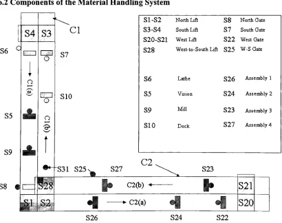
6.2
Components
oftheMaterial
Handling
System
43
6.3
Control
oftheCAMCELL Material
Handling
System
44
7
CAMCELL Automation
50
7.1
Introduction
50
7.2
Simulation
of aFlexible
Manufacturing
System
50
7.3
WTNCC
tagsusedin
theCAMCELL
Control Software
51
7.4
Inquire
52
7.5
Pallet Controller
54
8
Conclusions
57
List
ofFigures
Fig
No.
Name
ofFigure
Page No.
2
Data Communication for Process Control
6
2. 1
Structure
of a shielded2-core Profibus Cable
6
2.2
Profibus
Access
Techniques
7
2.3
Star
Topology
8
2.4
Ring Topology
9
2.5
ISO OSI Seven-Layer
model1
1
2.6
Simatic NET
topology
asusedin
theCAMCELL
application12
3
Programming
Languages
for Process Control
16
3.1
A rung in
aladder logic
program1
6
3
.2An
example of arung in
aLAD
program1 7
3.3
An
exampleofablock
in
aFunctional Block Diagram
18
3.4
An
example ofSTL instruction
1 9
3.5
Grafcet Program
20
3.6
A Graph
program22
3.7
A function block in SCL
23
4
Simatic PC Based Automation System
25
4.1
Components/architecture
oftheSimatic Automation System
25
4.2
Using
Step7
tocombinethehardware
withthesoftware28
4.3
Basic
tasksin
an automation projectusing
Step
7
29
4.4
Basic
architecturein
control applicationin
Siemens'
Technology
30
4.5
Project
Structure
withinSimatic Manager
3 1
4.6
Components
ofWinLC
32
4.7
Absolute
Addressing
33
4.8
Project
Structure
withinWTNCC Explorer
35
Fig
No.
Name
ofFigure
Page No.
5
Description
oftheCAMCELL
architecture39
5.1
CAMCELL
Hardware
Architecture
41
6
Control
oftheCAMCELL Material
Handling
System
43
6. 1
Schematic
oftheCAMCELL Material
Handling
System
43
6.2
List
ofInputs
usedin
thecontrol program45
6.3
List
ofFlags
usedin
thecontrol program45
6.4
List
of outputs usedin
thecontrol program46
6.5
List
ofregisters usedin
thecontrol program48
6.6
List
ofpassthroughoutputs49
6.7
List
of passthroughinputs
49
7
CAMCELL Automation
50
7. 1
Schematic
ofOPC Client-Server Architecture
usedin CAMCELL
5 1
7.2
WTNCC Screen for
theInquire
module53
Appendices
No.
Appendix
A
Siemens'Software Installation
B
Hardware Configuration
C
Communicating
Step7
withWTNCC
D
Accessing
theWTNCC
tagsviatheOPC
channelE
Quickstep
programfor
theconveyor controlF
Symbols
tableusedin
theStep7
G
LAD
programfor
theInquire
andPallet Controller
moduleAbstract
Manufacturing
Systems Integration is theprogressivelinking
and combination ofthevarious componentsofthe systemto merge their functional and technicalcharacteristics into a comprehensive interoperable
unit.Itrequires onetowork withdifferenthardwareand software.Thereare a number of vendorsproviding alargenumber of products.
Integrating
thesevarieties of products provides a greater valuethan thesum of thevalue providedby
theindividualproducts. Whathinderstheeffectiveintegration ofthese componentsisthe
diversity
inthedesignandtheuse oftheseproducts.Systems Integration iseasedby
well-establishedstandards in data communication, programming
languages,
application development environments and computeroperating systems.Many
vendors have attemptedto come upwith standardsthatarerelatively open.However,
when one has to integrate data among multiplevendors'
architecture, a new set of
challenges emerge.
The Siemens'
PC-based automation
technology
is anemergingtechnology
thatappears to provide robustarchitecture for
integrating
all elements ofthe manufacturing environment. Applications ranging from simple controlto distributedcontrol andfull-fledgedManufacturing
ExecutionSystems canbe developedusing
Siemens'
architecture. The primary focusofthisapplied research workisto
develop
aManufacturing
Execution System to control a flexible manufacturing system using Siemens PC-based automation technology. Thistechnology is implemented ina Flexible
Manufacturing
cell namedtheCAMCELL. The CAMCELLconsists oftwoCNC machiningcenters,assemblyrobots, and a visionsystem,all of which areinterlinked
by
a materialhandling
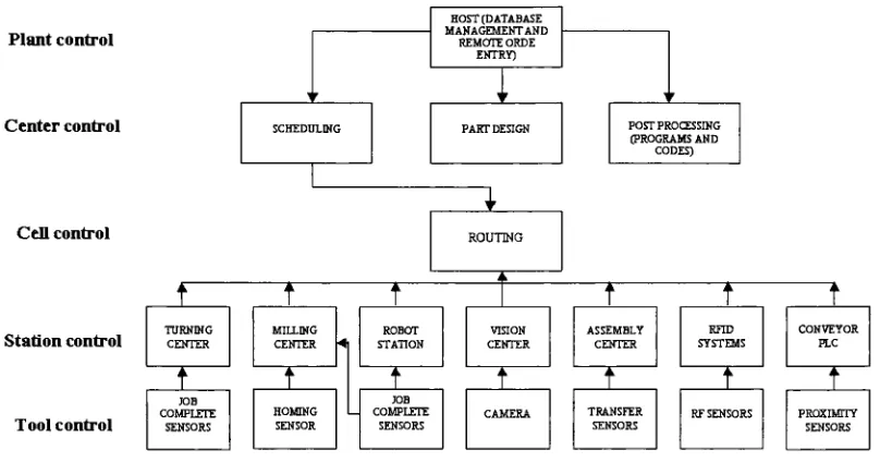
system.Thesoftware architecture oftheCAMCELL is basedonNIST's five levelhierarchy,
discussedbriefly
in the report.Specifically
it contains functionalmodules for order entry, schedulingand routing. Inadditionto these functionalmodules, thereare various support modules such as orderentrymodule, scheduler,routeretc, twoof which namedtheInquireandthePallet Controllerthat are implemented in this study. Siemens'
Step
7 and WTNCC software are used forthe control andSection
1.
Introduction
A systemis defined as a collection of elements or components thatare organizedtogetherfor a common purpose. [1]
Manufacturing
Systems Integrationis theprogressivelinking
and combination ofthe various components ofthe system to merge their functional and technical characteristics into a comprehensive interoperable unit. [2] System Integrationrequires us towork withdifferenthardware and software.Thereare a number of vendors providing a large number of products.
Integrating
these varieties of products provides a greater valuethan the sum ofthe value providedby
theindividual products. Whathindersthe effective integration of these components is thediversity
in the design and the use ofthese products.Computersystems arecontinuouslyevolving,operatingsystems arerapidly changingandtheprogramming languagesaregettingmore and more object oriented.
Systems Integration is eased
by
well-established standards in data communication, programminglanguages,
application development environments and computer operating systems.Many
vendors have attemptedto comeupwith standardsthatarerelativelyopen.Forexample, theSimatic PCS 7 isa process control systembasedon standardtechnologiesandthusoffers openness and also allowsittobe linked upto systems madeby
other manufacturers. Ithas a flexible architecture that facilitates horizontal integration among the processes as well as vertical integration in the company-wide information network andintegration to field engineering. [3]
Industrial17
Solutions from ABB are designed to perform as a
fully
integrated set of solutions across common
hardware,
software, engineering, spare parts, project management,training
and service components.They
are scaleable and open andhenceyou canimplementonly what you require now, and add
functionality
over time, as needs evolve. [41 The WestinghouseDistributed
Processing Family
(WDPF)
distributedcontrol andinformationsystem providesmodulatingcontrol, sequentialcontrol, and data acquisition fora wide variety of process applications. Ithas a dual
network architecture thatprovides effective and reliable communications and a deterministic networkfor real-time process control data and anopenEthernet Information
Highway
for file transfer, remoteaccess, and enterprise integration. It also offers theflexibility
tofully
integrate plant process control, local and wide area SCADA systems, PLC networks, and maintenance management andlaboratory
computer systemsin asingle,unified architecture. [5]IBM's SiViewStandard,
an advancedmanufacturing execution systemforsemiconductormanufacturers,provides a complete open, multi-platform environment with theindustry's richest
functionality
andlargestrangeofManufacturing
ExecutionSystems(MES)
applications,including
material management, equipment and process management, schedule management, process control,andfactory
automation. SiView Standardintegrateswith avarietyofthird-partysoftware to offer an end-to-end MES solution. [6]However,
when one has to integrate data among multiplevendors'
architecture,a new set of challenges emerge.
The Siemens' PC-basedautomationtechnology is anemerging
technology
that appears toprovide robust architecture forintegrating
all elements ofthe manufacturing environment. Applications ranging from simple controltodistributedcontrolandfull-fledged MEScanbe developedusingSiemens'The primaryfocus ofthis thesis isapplied research
leading
is tounderstandanddevelop
aManufacturing
Execution System to control a manufacturing cell named the CAMCELL. CAMCELL is a flexiblemanufacturingsystemcontainingtwoCNC machiningcenters,assemblyrobots,anda visionsystem,all of which areinterlinked
by
a materialhandling
system.Thesoftware architecture oftheCAMCELLis basedon
NIST'
fivelevel
hierarchy
[7]Specifically
itcontainsfunctionalmodulesfororderentry,schedulingandrouting. Inadditiontothesefunctionalmodules, there are various support modules(order entry, scheduler, routeretc.)twoof which namedtheInquireandthePalletControllerareimplemented inthisstudy.
This study aims to evaluate the Siemens' Automation System in terms ofits important features in the
context of Systems Integration. There are many communication standards that govern the data communication within a manufacturing cell. Such communication standards range fromdevice-to-device standardsliketheRS-232serial communication standardtoadistributednetwork communication standards like Industrial Ethernet.
Similarly,
there are varieties ofprogramminglanguagesstandards thatare popular in the process control field. Fromsimple graphicalprogramming languages like the Ladder Logic or thefunctional block diagramtoSequential
Programming
languagesand complexStructuredControllanguages,
thereare a number ofprogramming languagesthata control solutiondevelopercan chosefrom. Thesetwo
aspects ofSystems Integration inaddition to other problems faced inthe multi-vendor integrationare a
huge challenge to
bring
about effective Systems Integration. This study aims at studying the Siemens' AutomationSystemthrough theseperspectives.In section number two, we discussthe data communication standards popular within the process control field. Suchstandardsinclude Serial Communicationstandardslike
RS-232, RS-422,
RS-485,
andProfibusnetworks communication standards, Parallel Communication standards like IEEE-488 communication standardanddistributednetwork communication standardslike EthernetandTCP-IP.
Here,
we alsodiscussthe ISO OSI 7-layer model, which specifies the functions that are to be fulfilled at each level in communication systems. Inthissection we alsodescribetheSimatic NET Profibusnetworkthatisusedin
theCAMCELL.
In section numberthree, we discuss the programming languages currently inuse in the process control field. Such languages include Graphical
Programming
languages like the Ladder Logic(LAD)
and theFunctional Block Diagram
(FBD),
TextualProgramming
language like the Statement Lists(STL),
SequentialProgramming
languagesliketheGrafcetandGraph,
and alsoStructured Control languages.In section number
four,
we describe the General Architecture of the Siemens' Simatic PC-based Automation System. The various components ofthis architecture are SimaticControllers,
SimaticHMIs,
Distributed
I/Os,
the Simatic NETcommunication networkandtheStep
7configurationandprogrammingsoftware. Inthis section, we alsodescribethe Simatic Managerarchitecture. SimaticManager isthebasic applicationfor configuringthehardwareandprogramminglogicina control application.Maincomponents in this architecture are the Simatic PC
Station,
OperatorStation, WinLC,
which is the logic controller,Automation system. This section contains a brief descriptionofthese components ofthe overall Simatic
system architecture as well astheSimaticManagerarchitecture.
In section number
five,
we describe the CAMCELL through three different perspectives viz. theManufacturing
and MaterialHandling
perspective, Product/Process flow perspective and the Computerhardware
hierarchy
perspective.Insection numbersix,wedescribethematerial
handling
system oftheCAMCELL,
itscomponents anditsfunctions. We also describe the control program that runs the material
handling
system written in theQuickstep
programminglanguage.In section number seven, we describe the CAMCELL automation system. Here we describe the actual implementation of the Siemens' automation
technology
in the CAMCELL. Here we describe the implementationoftwofunctionalmodules oftheCAMCELLviz.theInquireandthePallet Controller.References:
[llhttp://searchwin2000.techtarget.com/sDefinition/0sidl_gci213083,00.html
[21www.its.bldrdoc.gov/fs-1037/dir-036/_5625.htm
[3]
http://www.sea.siemens.com/process/product/pa7ovrvw.html[4]
http://www.abb.com/global/[5]
http://www.westinghousepc.corn/wdpf-control/descriptions.cfm[6]
www.ibm.comSection
2.
Data Communication for Process Control
2.1 Introduction
Inthissection,we willfocuson various communication standards that arerelativelymore popularinthe
process control field. Communication standards are an agreed upon set of rules and guidelines that
govern communication between two
devices,
or two systems. There are two aspects to anycommunicationstandard, viz. the hardware aspect and the software aspect. The hardware aspect ofa
communication standard deals with such things as physical characteristics, electrical characteristics,
types of connectors and so on. On the other
hand,
the software aspect deals with the ways in whichinformation ispackagedandtransferred.Inthis section we willdescribe boththeseaspectsofthevarious
communication standards
leading
tothediscussionoftheSimatic NET Profibusnetwork,whichis a partoftheSiemens' SystemandisusedintheCAMCELLapplication.
2.2 Data Transfer Modes
mTherearetwodifferent kindsofdatatransfer modes,
1. Serialtransfer mode,or serialcommunication,
2. Paralleltransfer mode,or parallel communication.
2.2.1. Serial Communication
In Serial
Communication,
data istransferredfromsender toreceiver onebit at atimethrough a singleline or circuit.Thenameserial communication comesfromthefactthatthe serial porttakes
8,
16or32parallel bits from a computer bus and converts it as an
8,
16 or 32 bit serial stream. Each bit ofinformation istransferredin seriesfromone locationto another. Eachstream ofbitsis broken upto8
bitscalled words.Serialcommunicationisoftwo types.
Synchronous Serial Communication
Inthis typeof serialcommunication, thesending andreceivingends ofthecommunication are
synchronizedusinga clockthatpreciselytimes theperiodseparatingeachbit.
Asynchronous Serial Communication
By
introducing
a startbitthatindicatesthestart ofa shortdata stream, theposition of eachbitcanbe determined
by
timing
thebitsat regularintervals. Thetwosystems thendon'thavetobesynchronized
by
a clock signal.Whenthereceivingend ofthecommunication receivesthestartbit itstartsashort-termtimer.
By
keeping
streamsshort, there'snot enoughtimeforthe timer toget out of sync. This method is known as asynchronous communication because the sending
2.2.2. ParallelCommunication
Simultaneous transmission of the eight bit-voltages that constitute a byte is referred to as "parallel transfer".Whenbitshavetobemoved about withinthecomputer
itself,
theyaretransmittedalongwires. If the data to be transmitted is in 8-bits formatbytes,
then eight separate, discrete wires mustsimultaneously carrytheeight representative electrical voltagesbetweenthetwopoints.Paralleltransfer, then, is done byte-by-byte. Sinceall eightbitsarrive attheirdestinationatthe same
instant,
paralleldata transfercanbeaccomplished atextremelyhighspeeds.2.3 Serial Communication Standards
|21 Themost popular serial communication standardsare,1. RS 232communicationstandard, 2. RS 485communicationstandard, 3. RS422communicationstandard,and 4. Profibusnetworks
2.3.1. RS 232communication standard
RS-232communication standard wasintroduced in 1960
by
theElectronic Industries Association(EIA),
and is currently the most widely used communication protocol. It is simple and inexpensive to implement. Even thoughrelatively slow, it is adequate for most simple serial communication devices such as keyboards and mice. RS-232 is a single-ended datatransmission system, which means that it uses a single wirefor datatransmission. Sinceuseful communicationis generallytwo ways, atwo-wire systemis employed, one to transmitand oneto receive. Because signalstraveling
this single wire are vulnerable todegradation,
RS-232 systems are recommended for communication over short distances(up
to 50feet)
and at relativelyslowdata rates(up
to 20 kbps). RS-232 is usedto connectonlytwo systems.'I2'2.3.2. RS 422communicationstandard
RS-422 (EIA RS-422-A
Standard)
is a serial communication standard used on Apple Macintosh computers. RS-422 uses adifferential electrical signal, as opposedtounbalanced signals referenced to ground with the RS-232. Differentialtransmission, which uses twolines each to transmit and receive signals,results ingreater noiseimmunity
andlongerdistances as comparedto theRS-232. Thegreater noiseimmunity
and distance arebig
advantages in industries.RS-422,
like RS-232 is also used to connecttwosystems.[1 ]2.3.3. RS485communicationstandard
PC or other controller for data collection,
HMI,
or other operations. RS-485 is a superset ofRS-422;
thus, all RS-422 devices may be controlled
by
RS-485. RS-485 hardware may be used for serial communicationfor upto4000feetof cable.2.3.4. Profibus|9'
2.3.4.1 OverviewofProfibus Network
Profibus is an acronymfor "Process Field Bus". It isa modified version of the RS 485 standard and followstheinternationalstandards EN
50170,
EN 50254andIEC 61158[10]. It is a vendor-independentstandarddocumentedin thevolume 2ofEN 50170. Thetransmissionmediumis either a coppercable networkbasedon a shielded2-corecable or afiber-opticcable network as showninfigure2.1.
PVCouter sheath
Cores,solidcopper s^-f-^^Z^
'V^CX
Copper braidshieldAluminum foil
Plastic foil Cellular PE insulation
Filler
Fig
2.1 Structureof a shielded2-core ProfibusCableThetransmissionspeeddeterminesthelengthofthecable within a segment.Themaximumlengthatthe highest transmission speed (12
Mbit/sec)
is 100m and the minimum cable length at the lowest transmissionspeed(9kbit/sec)
is 1000m.Thenetwork canbeexpanded with repeaters.The Profibus supports the exchangeofinformation between field devicesand with systems at a higher
system level. It is mainlyused to transfer small to medium quantities ofdata. Itoffers a standardized
interface forthe transferof process inputand process output data between Simatic S7 stations andthe field devices.
2.3.4.2 Accesstechniques
Thenetwork access techniquefor PROFIBUS corresponds to the"Tokenbus"
Matterftto* assignment
Fig
2.2. Profibus Access TechniqueWhen a station receives the token (addressed to
it),
it has permission to send telegrams. The timeallowed is specified
by
the so-called tokenholding
time. Once this has elapsed, the station is only permitted to send one morehigh-priority
message. Ifthe station is not waiting to send a message, itpassesthe tokenontothenext station inthelogical
ring
immediately. The corresponding token timers("maximum token
holding
time",
etc.) are configured for all active stations. Ifan active stationis inpossession ofthe token and connections to passive stations are configured for it (master/slave
links),
thesepassive stationsare queried(e.g. variables areread) ordatais sentto them(e.g.set point values).Passivestations never receivethe token.Thisaccesstechnique allows stationstobeadded and removed underoperatingconditions.
2.4
ParallelCommunication
Standards
Parallelcommunicationis characterized
by
multiplebitstransfer thatleadstohigher datatransfer rates,overrelativelyshorterdistances.
Theparallel communication greatly increases transfer speeds
by
using an eight-wire connector, whichtransmitstheeightbits inabyteofdatasimultaneously, thussendingan entirebyteofdata inthe timeit
takes to send a single bit in a serial system. This byte of data is supplemented
by
several otherhandshaking
signals,eachsent onitsownwire,which ensurethatdatatransfer takesplacesmoothly[3]2.4.1. IEEE488
(GPIB)
'4|The IEEE-488bus was developedto connectand control programmable
instruments,
andtoprovide a standard interface for communication between instruments from different sources. Hewlett-Packardoriginally developedthe
interfacing
technique, and calledit HP-IB. Sincetheinterfacewas soversatile,thattheIEEE committee renameditasGPIB (General Purpose Interface Bus). The IEEE-488 interface
systemconsists of16 signallines and 8 groundlines. The 16 signallines are dividedinto 3 groups(8 data
lines,
3 handshakelines,
and 5 interfacemanagementlines). ThestandardIEEE-488 cablehas bothThe IEEE-488 bus specifies a maximumtotal cable lengthof20 meters with no morethan20 devices connected to the bus and at least two-thirds ofthe devices powered on. Amaximum separation of4 metersbetween devicesand an average separation of2meters overthefull busshouldbe followed.
2.5 Network Interfaces
2.5.1. Network Topologies
Therearetwowidelyused networktopologies
Star
Topology
Ring Topology
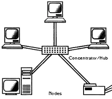
2.5.1.1. Star
Topology
'5|Star
topology
isa network configurationinwhichthereisa central pointtowhichagroupof systemsare [image:20.545.202.390.310.476.2]directly
connected.Withthestartopology,alltransmissionsfromone systemtoanother passthroughthe central point, which may consist of a device that plays a role in managing and controlling communications.Fig. 2.3 Star
Topology
2.5.1.2.
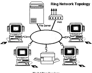
Ring Topology
|6'A ring is a network
topology
or circuit arrangementin which each device is attached alongthe same signal pathto two otherdevices,
forming
a path inthe shape of a ring. Eachdevice inthe ringhas a unique address. Information flowisunidirectional anda controllingdevice intercepts and managesthegi
Ring
Network
Topology
'I'rrmriJlFig
2.4Ring Topology
2.5.2 TCP/IP
TCPandIPweredeveloped
by
aDepartmentofDefense(DOD)
research projecttoconnect a number ofdifferentnetworks designed
by
differentvendors into a network of networks (the "Internet"). Severalcomputersina smalldepartmentcan useTCP/IP
(along
with otherprotocols) on a singleLAN. The IPcomponent provides routing fromthe departmentto theenterprise network, then toregionalnetworks, and
finally
to the global Internet. As with all other communications protocol, TCP/IP is composed oflayers:
IP - isresponsiblefor movingpacket ofdata fromnodetonode.IP forwardseach packetbased onafour-byte destinationaddress(the IPnumber).
TCP- isresponsible
for verifyingthecorrect
delivery
ofdata fromclienttoserver.Datacanbe lost intheintermediatenetwork.TCP isusedby
applicationsthatrequire reliabledatadelivery. TCPuses a check-sum withthedata sentthat theTCPlayerattheother end usestoverifythat the data arrived undamaged. If the data checks out, the receiving TCP layer sends anacknowledgment back to the sender. Ifit arrives
damaged,
the receiver discards it and the sender,afteran appropriatetime-out period,resendsit.But beforedata is transmitted,the twohostsexchange a
three-way
handshake. Thesender sends a signaltelling
the receiverit wantsto setupa connection andhowthe datawillbe sequenced. The receivinghost sends a signal back acknowledging receiving the signal. The sending host sends a signal back
acknowledging the acknowledgement and begins data transmission. The connection at the end ofthe
[image:21.545.137.457.50.305.2]2.5.3 Ethernet
Ethernet is a local area network
(LAN)
technology
that transmits information between computers atspeeds of10and100millionbitsper second(Mbps).
Currently
themostwidelyused version ofEthernettechnology
isthe 10-Mbpstwisted-pairvariety.The 10-MbpsEthernetmedia varietiesincludetheoriginalthickcoaxialsystem,as well asthincoaxial,
twisted-pair, andfiberoptic systems.Themost recentEthernetstandarddefinesthe new 100-Mbps Fast
Ethernetsystems,which operates overtwisted-pairandfiberoptic media.
Each Ethernet-equipped computer, alsoknownas a station, operates
independently
of all other stationsonthenetwork andthere isno central controller. Allstations attachedtoanEthernetare connectedtoa
shared signalingsystem, also calledthe medium. Ethernetsignals are transmitted serially, onebitat a
time, overthe shared signal channelto everyattached station. To senddataa stationfirstlistensto the
channel, and whenthechannelis idlethestationtransmitsits data intheformof anEthernet
frame,
orpacket.
After each frame transmission, all stations on the network must contend equally for the next frame
transmission opportunity. This ensures that access to the network channel is
fair,
and that no singlestation canlockouttheother stations.Accesstotheshared channelisdetermined
by
themedium accesscontrol
(MAC)
mechanism embedded in the Ethernet interface located in each station. The mediumaccess control mechanismis based on a system called Carrier Sense Multiple Access with Collision
Detection (CSMA/CD).
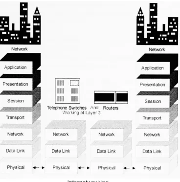
2.6. ISO OSI Seven-Layer Model
[8]The Open Systems Interconnection
(OSI)
7 Layer Model is the product of years of workby
manyorganizations.The InternationalStandards Organization
(ISO)
hascompiled alltheresults.Thisstandard is called a reference model. It specifies the functions that are to be fulfilled at each level incommunicationbetweentelephone systems, or computers. These 7 layersarethought tobe adequateto
encompass all communicationsfunctions.
Layer 1: The Physical Layer is concerned with
transmitting
rawbits,
electricalimpulses, tight,
andradio signals over a communications medium. The primary concern of a designer for this layer is
mechanical, electrical, or optical matters. Specifications for wave shapes, signaling rates, cables and
connectorsareinvolvedinthislayer
Layer 2: The Data Link Layertakes the bitspassed
by
the physicallayerand creates and recognizesframe
boundaries;
by
this techniqueittransfersunitsofinformationto theother end ofthephysicallinkIt also contains the rulesgoverning access to thenetworkcable,Media Access Control
(MAC)
whichNetwork
mi
m\
mm mini
in
mini
Telephone Switches And Routers
Working
at Layer2Data Link
Network
DataLink
Network
Data Link
Transport
Network
Data Link
F,
Physical *- * Physical *- ? Physical ? Physical
Intornotworkinq
Fig
2.5 OSI ISO 7 layermodelLayer3: The Network Layercontrols operations of sub networks that mightintervene betweenthe two
communicationdevices.This layerroutesinformation among differentnetworks.
Layer 4: The Transport Layersplitsup information intoappropriate sizes(segments
information)
soitwillfit intopackets oftherightsizeforthe networks
being
used.In manycases,itensures allthepacketsarrive attheother end with errors and assembledinorder and withoutduplication.
Therefore,
itprovidesend-to-enddata
integrity
andqualityof service.Layer 5: The Session Layercontrolstheestablishment and continuation of a particularcommunication
between devices. Itcoordinates interaction betweenend-applicationprocesses,
keeping
thetwodevicestalking
toeach other andmaintaininga connection.Layer 6: The Presentation Layerperforms conversions oninformation. These include conversionof
code sets, encryption, text compression, andprotocol conversion for virtual terminal communication.
Thislayermayalsotranslatefile formatsthatdiffer betweendevices.
[image:23.545.98.467.50.423.2]Layer 7: The Application Layercontainsthefinalparticularsrequiredforprogramsto communicate. This layer establishes means for making the network appear transparent to user
devices,
joining
thecommunications streamtotheindividual device.
2.7
Topology
ofSimatic NET Profibus
network usedin
theCAMCELL
2.7.1.OverviewoftheSIMATICNETsystem
SIMATIC NET is the name ofthe communication networks connecting SIEMENS programmable
controllers,hostcomputers,workstations and personal computers. SIMATIC NETincludesthefollowing:
The communication network consisting of transmission media, network attachment and
transmissioncomponents andthecorrespondingtransmission techniques Protocolsand services usedto transferdata betweenthedevices
The modules oftheprogrammable controller or computerthatprovide the connectionto the
communications processors.
To handle a variety of tasks in automation engineering, SIMATIC NET provides different
communication networkstosuittheparticular situation.The
topology
ofrooms,buildings, factories,
and complete companycomplexes andtheprevalent environmental conditions meandifferentrequirements. Thenetworked automation components also makedifferentdemandsonthecommunication system. The communication network used in the CAMCELL application is the Profibus network, which was discussedearlierinthissection.TheSIMATIC NET
topology
usedintheCAMCELLapplicationisshownbelow inthefigure 2.6DPrnoBtef
v.iihPRORBUS
PC
CPSS13
(CP5613)
>lipki
tf- ;las
(ET
200M)
3V^K
JTK fb>I
WWW,
. ,|
Proust-Pr.*I
(Field
Devices)
Fig
2.6 SIMATIC NETtopology
as usedintheCAMCELLApplication.[nl2.7.2CP 5613 Communication Processor
In any SIMATIC S7 application, aCommunicationProcessor
(CP)
is always requiredfortheProfibusThe CP 5613 is aPCI card with a microprocessorthatallows connection of a SIMATICprogramming
device to Profibus under Windows NT 4.0 or Windows 2000. The CP 5613 can also be used to
implementcontroltaskson a
PC,
thusfacilitating
PC basedcontrol.The CP 5613 card is a short PCI card with a 9-pin sub D socket for connection to Profibus. It has
diagnostic LEDs for installation and commissioning and
during
operation ofthe module. Inorder toprovide access to theprocess
data,
the CP 5613 operates as theProfibus master modulebuffering
the process image (input/output and diagnosticdata)
in the DP RAM(memory
area on the CP). High performancedatacommunicationsishandledautonomouslyby
theCP 5613 hardware. Theprocessdata from the slaves are always consistent asthey
all originate from one and the same DP (decentralizedperipheral)cycle.
2.7.3 ET 200 M distributed I/Omodule
The ET 200-M is a modularI/O station. It is the passive station ofthe Profibus field bus and has a
maximumdatatransferrate of12Mbit/s. AtypicalET 200Mstation consistsof:
Power
Supply
IM 153 interfacemodule
Up
to 8 I/OmodulesNo specific slots are assigned tothe I/O modules.
Any
combination of modules is possible. The ET200M isconnectedto thePROFTBUS-DPvia anIM 153 interfacemodule.The inputsand outputsofthe
modularET 200M I/Ostation canbeaccessedfromtheuser programinthePLC inthesame manneras
theinputsand outputs ofthecentral controller.
Communicationviathebussystemis handled completely
by
themasterinterfacemodule inthe centralcontroller andtheTM 153 interfacemodule.
2.8
Glossary
ofTerms
Data bits: Data bit is a measurement ofthe actualdata bits ina transmission. Standardvalues for
the datapackets are
5, 7,
and 8 bits. A packet refersto a single bytetransfer,including
start/stopbits,
databits,
and parity.Sincethe number of actualbits dependsontheprotocolselected, the termpacketisusedtocover allinstances
Stopbits:
Stop
bits are usedtosignaltheend of communicationfora single packet.Typicalvaluesare
1,
1.5,
and2 bits. Morethebitsusedfor stopbits,
greateristhe leniencein synchronizingthe differentclocks,butslowerthedatatransmissionrate.Parity:
Parity
is a simple form of errorcheckingthat is used inserial communication. Therearefourtypesof parity: even, odd, marked, and spaced.Theoption ofusingnoparityisalso available.
Foreven and oddparity,the serial port sets theparity bit (thelast bitafterthedata
bits)
toa valuetoensure thatthetransmissionhas aneven or odd number oflogic highbits. Iftheparity isodd, then
theparity bit is
1,
resulting in 3 logic-high bits. Markedand spacedparitydoesnotactuallycheck the databits,
but simply sets the parity bit high formarkedparity or low for spaced parity. Thisallowsthereceiving device toknowthestate of a bitto enablethedevice to determine ifnoiseis
corruptingthedataorifthe
transmitting
andreceiving deviceclocks are out of sync.Baudrate: Baudrate is a measurement of speedforcommunication. It indicatesthenumberofbit
transfers per second. For example, 300 baud is 300 bits per second. Common baud rates for
telephone lines are
14400, 28800,
and33600. Baudrates greaterthanthese arepossible, buttheserates reducethedistance
by
whichdevicescanbeseparated.Bus: In a computer, bus is the data path on the computers'
motherboard that interconnects the
microprocessor with attachmentsto the motherboard inexpansion slots. Suchattachmentsmay be hard disk
drives,
CD-ROM drives etc. Onanetwork, abus is atransmissionpathon which signalsaredroppedoff or pickedupateverydeviceattachedto theline.
Only
thedevicesaddressedby
the signalspayattentiontothem,
theothersdiscardthe signals.Thereare varioustypesofbusavailable such asISAbus,
PCIbus,
EISAbus,
IDEbus,
ETDEbus,
VMEbusetc.Port: On computer and telecommunication
devices,
a port is generallya specific place forbeing
physicallyconnectedto some other
device,
usuallywith asocket andplugof somekind.Typically,
a personal computer is provided with one or more serial ports andusually one parallel port. The serial port supportssequential,onebit-at-a-timetransmission toperipheraldevicessuchas scanners andthe parallel port supports multiple-bit-at-a-timetransmission todevicessuch as printers.Standard: Anagreed upon set of rules and guidelines.
Many
standards are evolvedfrompopularmethods while others are crafted
by
professionalgroups(ANSI, ISO,
etc.)LAN: A local area network
(LAN)
is a group of computers and associated devices that share acommon communications line and
typically
share the resources of a single processor or server within a small geographic area(forexample,withinan officebuilding).WAN: A computer network that spans a relatively large geographical area.
Typically,
a WANconsistsoftwoor morelocal-areanetworks(LANs). The largest WAN inexistenceistheInternet. Firewall:Firewallisa systemdesignedtoprevent unauthorized accesstoorfroma private network. Firewalls canbe implemented in both hardware and software, or a combination ofboth.Firewalls
are
frequently
used to prevent unauthorized Internet users from accessing private networks connected to theInternet,
especially intranets. All messages entering orleaving
the intranetpassthrough the
firewall,
whichexamines each message andblocksthosethatdo not meetthespecifiedsecuritycriteria.
Router: Router isa network devicethat sends and receivesNetworkprotocol-data units
(packets)
and relays packetsfromonedevicetoanotherthroughthenetwork.
Hub: Hub is localarea networkequipmentthatallows multiple networkdevicestobeconnectedto
theLAN cablingsystemthrougha central point.
Token Ring: Token ring is a LAN data linktechnology, in which systems are connectedto one
anotherusing a point-to-point twisted
-pair cable segments to forma ring structure.A systemis allowedto transmitonlywhenit hasthetoken,whichispassedfromonesystemtoanother around
thering.
References:
[1]
http://www.rad.com/networks/1995/rs232/rs232.htm[2]
http://www.quatech.com/Application Obiects/FAQs/comm-over-rs-232.htrn[3]
http://www.quatech.com/Application_Obiects/FAQs/cornm-over-parallel.htm[4]
http://www.techsoft.de/htbasic/tutgpib.htm[5]
http://fcit.coedu.usf.edu/network{6]
http://hs.stcloudstate.edu/cirn/courses/im644/ring.html[7]
http://www.ots.utexas.edu/ethernet/[8]
http://web.singnet.com.sg/~psylence/c3p03.htm[9] Berger,
Hans.Automating
withSIMATIC. SIEMENS 2000.[10]
http://www.profibus.com/profibus.html[11]
http://www.sea.siemens.com/autogen/docs/net/pfb/man/DP Base Program Interface for 5613.pdf[12]
http://www.synchrotech.com/support/serial_standards.htmlSection 3.
Programming
Languages for Process
Control
3.1 Introduction
Inthissection we shalldiscuss the variousprogramming languagesusedto writecontrollogicforprocess
control.There are variousprogramminglanguagesavailablefor writingcontrollogic. Thevarious typesof
programming languages include graphical programming
languages,
statementlists,
sequentialprogramming
languages,
and structured Control Languages.First,
we describe these programming languages and also discuss programming languages within each category.Next,
we describe the Ladder Logic (abbreviated asLAD inthe Siemens'Technology)
andtheFunctional Block Diagram (abbreviatedasFBD in the Siemens'
Technology),
which are graphicalprogramming languages and StatementLists,
which is a textual programming language.
Next,
we will discuss theGrafcet, Graph,
and the HiGraph programminglanguages,
which are sequential programming languages.Next,
we will discuss the Structured Control Language. We shall discusstheimportant features of eachprogramming languageandalsodiscusstheiradvantages anddisadvantages.
3.2 Graphical
Programming
Languages
Graphical programminglanguagesmake use of symbols andicons inordertobuildcontrollogic. Graphical
programming languagesare especiallysuitable for representing bit
logic,
ina formeither modeled on arelay ladder logic diagram
(LAD)
orresemblingan electronic circuitdiagram (FBD). 3.2.1 Ladder Logic(LAD)
Ladderlogicprogramming isa graphical representation oftheprogramdesignedtolook like relay logic.[4) In
LAD,
user writes the program for the control applicationby
arranging graphical program elements.Thesegraphical program elements consist ofcontacts,coils and
boxes,
which arelinkedtogetherinaform resembling a relay ladder logic diagram. InLAD,
the entire program is containedinnetworks. ^Eachnetwork consists of onerung, thatisalogic operating ina coil orbox. Each rung isa combination ofinput
conditions
(symbols)
connectedfrom lefttoright,
withthe symbols that represent the output atthefar right. Thesymbolsthatarerepresentedasinputsare connectedinseries, parallel,or some combination ofthe twotoobtainthedesired logic.t2)
itacts
Run
3.2.1.1 Contactsin LAD
Contacts are usedinLAD programming language to checkthe states of
binary
addresses, such as inputs.By
arrangingthecontactsin series orparallel, logic operations canbeperformed. There aretwo typesofcontact;
Normally
OpenContacts andNormally
Closed Contacts. Inanormallyopencontact, the input ischeckedforahighstate, thecontact closesiftheinputturnshigh. Inanormallyclosedcontact,theinput is
checkedforalowstate,thecontact closesiftheinputturnslow. 3.2.1.2 Coils in LAD
Coilsare usedin LADprogramstoset or resetbitaddresses such as outputs.Coilsenergizes thebitaddress
when the power flows throughthe coil, and de-energizes the bitaddress whenthe power stops
flowing
through it. Coils are also used to control timer and counterfunctions,
call blocks without parameters,performjumpstoadifferentplaceintheprogram,and so on. 3.2.1.3 Exampleof anLAD rung
Fig
3.2 Anexample of arung inaLADprogram|S1Inthe aboveexample,an outputS isenergized orturned
ON,
when eitherinput SIorinput S2 isenergizedorturnedON.
3.2.1.4 AdvantagesofLAD
The Ladder Logic
Programming
offersmanyadvantages.Someoftheadvantages are asfollows,
1. The LAD programming language is a part ofInternational Electrotechnical Commission
(IEC)
61131-3standardfor Industrial Control Programming.[6]
2. It isthemostpopularlyusedprogramming language forcontrolprogramming
3. Itis reasonably
intuitive,
especially fortechnicianswithrelaylogicexperience [214. It is particularlyeffective inan on-line mode,whenthePLC is actually performingcontrol. The
operationofthelogic isapparentfromthe
highlighting
of the variousrelaycontacts and coils on the screen,whichidentifiesthelogicstateinrealtime.[2]5. Itissimple andeasytouse
3.2.1.5 DisadvantagesofLAD
Ladder
Programming
hasbecomeone ofthemost popular graphicallanguages for programming PLCs butunfortunatelyhasa number of problems.[7]
1. The laddersymbolsvary between different PLCproducts.
2. Poor facilities forstructured orhierarchicalprogramdecomposition
3. Poor facilities for addressingandmanipulating datastructures,
4. Limitedfacilities for
building
complexsequences, 5. Limitedcontrol over programexecution,6. Facilities forarithmetic operations are cumbersome.
3.2.2 Functional Block Diagram
(FBD)
Functional Block Diagramisanother graphical
language,
popularin Europe. FBDprogram elements appear asblocks that are "wired" together, analogous to circuitdiagrams. It iswell suited for representingbatch control applications.[91InFBD,
control programs are createdby
interconnecting
ANDandORboxes.FBDprovidesfunction boxes for performing logic operations on signalstates, simpleboxes for processingthe
result oflogicoperations and complexboxes for non-binary functions.
3.2.2.1 Boxes in FBD
There aretwo types ofboxes in FBD. Simple boxesoperate onbit addresses,likeoutputs. These usually
only have oneinputand maycontain additionalletters or symbols. Thereare simple boxes for settingor
resetting bitaddresses,evaluatingsignaledges, settingorresettingtimerand counteraddresses, and so on.
Complexboxesare usedforprogram elements withnon-binary functions.
3.2.2.2
Binary
Functions in FBDBinary
functions are usedin FBD to checkthe signal states ofbit addresses, such asinputs,
and performlogic operations onthem. Thefunctions available are
AND, OR,
and XOR. Allthese functions canhavemore thantwoinputs. The function boxes canbe interconnectedto program complex logic operationsin one network.
3.2.2.3 Exampleof anFBD Block
1.1 ,=-i
Q4.D
Fig
3.3 Anexample of ablock in Functional Block DiagramIntheaboveexample, theoutputSturns
ON,
when eithertheinput 1 1.1 or11.3turnsON.3.2.2.4 AdvantagesofFBD|8]
The Functional Block Diagramoffersthe
following
advantages,1. Simultaneous programmingand
documenting (overview,
comments, reliability,informationflow)
2. Universal applicability (Signalprocessing, numeric, arithmetic,
integer,
floating
point)3. Structured programming (defineand callsubroutines)
4. Standardizedset ofFunctionsandFunctionBlocks
3.2.2.5 DisadvantagesofFBD
Following
arethedisadvantagesoftheFunctional Block Diagram1. Poor facilities forstructuredorhierarchicalprogramdecomposition
2. Limitedcontrolover program execution
3.3 Statement List
(STL)
STL is a text-oriented language in which thecontrol task canbe described in the formof a list. It very
muchlooks liketheshort and simplelinesofassemblycodes. [U1Thusthecontrol programiswritteninthe
form of a series of statements. Each statement contains an instructionthat defines what is to be done.
Depending
on thetype ofinstruction,
thismaybefollowedby
an address thatdefineswhat actionistobedoneto. The elements ofthe statement lists closelyresemble the mnemonics of microprocessorassembly
languages.[11)
3.3.1 Exampleof anSTLprogram
NETWORK
1
LD
10.0
A
10.1
=
QO.O
NETWORK 2
LD
I0.4
0
I0.5
=
Q0.1
Fig
3.4 Anexample ofSTL instructionAstatementlistprovides another view of a set ofinstructions. The operation, whatistobe
done,
is shownonthe left. Theoperand, the itemtobe operated on
by
the operation,is shown ontheright. Inthe abovefigure,
in network1,
outputQO.O turns highwhenthe inputs 10. 0 and 10. 1 both turnhigh. Onthe otherhand,
theoutputQ0. 1 turnshigh,
when eithertheinput 10.4or10.5turnshigh.[12]3.3.2 AdvantagesofSTL programming
Statement Listsofferthe
following
advantages,[13]1. STLis verysimilartoanassemblycode,hencethecode canbe easilyread
by
everyone2. STL'sgenericalgorithms allow algorithmstobeappliedtomany differentstructures
3. STL is easytolearn.The
library
isquite smallowingtothehighdegreeof generality.4. STLcontainersareveryclosetotheefficiencyof
hand-coded,
type-specificcontainers.3.3.3 DisadvantagesofSTL programming
Following
arethedisadvantagesoftheFunctional BlockDiagram,
[13]1. Error checking is difficult in STL. Thismeansthatifthe programmer makes anerror,an errormay
ormaynotoccur whentheerroneousinstruction ismade,but itwill puttheprograminan unstable
state(e.g.
Writing
offtheend of an array).2. Accesstothe exact sourcethatone usesmay be
difficult,
soiftheuser needs specificinformationaboutcode
details, they
maynotbeaccessible.3.4 Sequential
Programming
Language
Sequential
Programming
Language is a method ofrepresenting thekey
elements of a sequential process,i.e. conditions required forpassing fromone stateto another, andthe effects present while ina particular
state.[10]
Insequential controlsystems,unlike logiccontrolsystems, thestatic assignment oftheinputsignalsto the
outputs is not ofimportance. It's the chronological sequence ofthese assignments that is important. The
control processesthatare executed one aftertheother aredivided into individualsteps. A stepconsists of one or more actions.
Only
theaction inan active step(step
currentlybeing
executed) is performed. Thenextstepcannotbeprocessed untilthe transitionconditionsare met.Thetransitioncanbedependentonthe process,or canbe dependenton atimefactor.tl]
3.4.1Grafcet
Grafcet is aninternational standardforsequentialfunctionchartsthatwas released
by
theIEC in 1988.[17] It is atype offlowchart representationspecifically developed forthe needs ofindustrialcontrol systems.Sequentialoperationsare representedin Grafcetasa series of steps.Theconditions requiredtomovefrom
onestepto thenext are referredtoastransitionconditions.Thesteps are represented
by
numberedsquares, wherethe step comprises of one or more on-off or analogtype actions. ['9]Atransition, which separatessteps, andisrepresented
by
ahorizontalhash,
containsthelogicconditionforterminating
theexecution of thestep.^ ' Themethod canbeusedas adesigntoolforwhatevertechnology
isbeing
usedtocontrolthe system-relays,pneumatic
logic,
orPLCs.[18] 3.4.1.1 Exampleof aGrafcetprogramOpen_Gnp
~~\~ Start
2 + Arm_on_level_l
Grip_closed
4 __
Arm_on_leve1_2
5
Fig
3.5 Grafcet ProgramIn the above example, there are steps and transitions
taking
place in sequence. The steps are shown insquares andtransitionsare shownin horizontal hashes. 3.4.1.2 AdvantagesofGrafcet
Following
aretheadvantages ofGrafcet,
1. Grafcetissupported
by
theIECstandard [l7]2. In executingthe
Grafcet,
the PLCneedonlyscantheactive steps andthe succeedingtransitions.Hencescantimesare reduced withGrafcet.[I8]
3.
Being
developed for sequential processes, Grafcet has outstanding features such as parallelprocessing.
4. Grafcet application can be transferred into different controllers. With the
help
of software likeCadepa [l91 the standard Grafcet code can be converted into machine code formost brands of
PLCs. Itcanbetransferredinto ladder logic for Allen
Bradley
PLC-5,
Modicon984,
Siemens S5and others. [1?1
3.4.1.3 DisadvantagesofGrafcet
Following
arethedisadvantagesofGrafcet1. Notaverypopularlanguage
3.4.2 Graph
Graph isa sequentialprogrammingmethodforsequential control systems.tl]Usercan writetheconditions
enablingtransitionsfromonestepto thenextin LAD orSTL. Alternativeor parallel
branching
extend the scope ofthe linearexecution of consecutive steps.WithGraph,
operations within a process are configuredand programmedina standardized
display
mode(incompliance withIEC 61131-3). Theprocess(e.g. the manufacture of a component) is divided into sequential or simultaneous steps. This division makes thestructureofthePLCprogram easiertounderstand and also easierto analyzeintheevent of a malfunction. Thisis particularlyusefulin manufacturingtoavoidcostly downtimes.tl4]
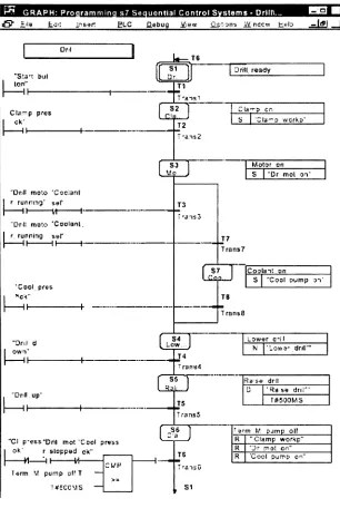
3.4.2.1 Exampleof a programin Graph
In the operation sequences, the individual steps of a process and the transitions to the next steps are
representedas rectangles andlines as shownin figure 3.6.
Qualifiers,
withinthesteps, caninitiateactions. (E.g. time-delay).If,
forexample,theoperatingsequencedescribes adrilling
process,the "lowerthedrill"willbe astepandthe"motorON"
willbean action. Thetransitions describethe conditions under which a transitionto thenextstep shouldoccur.
Moreover,
interlocking
andmonitoringconditions canbe definedfor everystep.An interlockcanbeusedtopreventthe execution of actions.
Monitoring
conditions enablethe recognition of operational faults. All conditions
(transitions,
interlocking
or monitoring) can beprogrammed eitherin LADorFBD.
Wl GRAPH:Proaramminqs7SequentialControlSystems- Drill\..
&"
[image:34.545.115.421.53.509.2]iie ai'. intar? LC fiebug jfjew jSpVana Mndcw Heb .sdlSJJ
I<MMM| JI "Sla-t but ten" II Clamp pres II
"Dnli rnolo 'Cacianl r
ruftmnq*sal'
II
~M
h'DM: rnaso "Cooianl. f running sr
II II h
'Cool.pres II r own" II "Drtt up-II "Cip-ess ok' H Term V
"Drili mot"Cool press rslopped ok"
-M
-)r-pump of?T
T*CCMS
UP
T6
S1 Drill,ready
TI
S2 Pa..
S I'Cte'-owcrka'
S3 Moiar on
S
|
"Dr mol ot'T3
ITans3
J7
Traris7
S7 Coolaii on
S Xool oump 31'
TS
TransS
SA
Lew..
LOwar eni
U 'low9'
.
dnir*
TransS
Raj. J
Rase dr:l! stass dri;r
t#50OMS
r s arm f/ pjmp olf
"Clamp
workf"
'Drmol c?r 'Cool puins
S1
Fig
3.6 A Graphprogram3.4.2.2 AdvantagesofGraph
Following
aretheadvantagesoftheGraph programminglanguage,
[15]1. Graphenables clearconfiguringoftheprocessintheplanningphase
2. Graphprovidesclear graphic representation oftheprocessusingsequencechains,resulting in easy
maintenanceand adaptation of programs
3.
Easy
troubleshooting
with internal diagnosticsfunctions,
resulting in minimizing of expensive3.4.2.3DisadvantagesofGraph
Following
are thedisadvantagesoftheGraph programminglanguage,
1. Graphissuitableonly forsequential control.Logiccontrol cannotbeprogrammed
by
Graph. [15]2. The transitions and steps needto beprogrammedineitherLADorFBD.Hence Graph is notan
independent language likeLADorFBD.
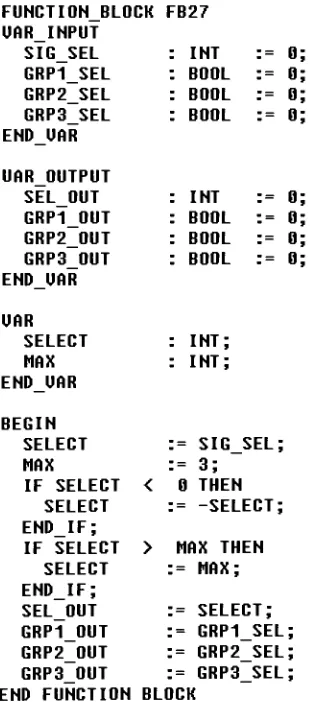
3.5 Structured Control Language
Structured Control Language
(SCL)
is a PASCAL-like high-level language optimized for programmablecontrollers. SCL is in compliance with IEC61
131-3,
and is especially suited to the programming of complex algorithms orfor data processingprojects.[141Apartfromtraditional control tasks, structured control language assists in performing data management
tasksand complex mathematical operations.tl6]
SCL statements consist ofexpressions, controlstatements, functions and blockcalls. Expressions assign
values, which can also be result of arithmetic and logic operations or comparison functions. Control
statements executetheprogrambranchesor repeat sections of a program.
FUNCTI0N_BL0CK FB27 UAR INPUT
SIG SEL : INT = 0
GRP1 SEL : BOOL = 0
GRP2 SEL : BOOL = 0
GRP3 SEL : BOOL = 0
ENDJJAR
UAR OUTPUT
SEL OUT : INT = 0
GRP1 OUT : BOOL = 0
GRP2 OUT : BOOL = 0
GRP3 OUT : BOOL = 0
ENDUAR
UAR
SELECT : INT;
MAX : INT;
ENDJJAR
BEGIN
SELECT = SIG SE
L;
MAX =
3; IF SELECT < 0 THEN
SELECT = -SELEtT;
END IF;
IF SELECT > MAX THEhI
SELECT =
MAX; END IF;
SEL OUT = SELEC1
GRP1 OUT = GRP1 S
EL;
GRP2 OUT = GRP2 S
EL;
GRP3 OUT = GRP3 SEL;
//make it positiue
//limit to MAX
END FUNCTION BLOCK
Fig
3.7 A function block in SCL [image:35.545.116.271.324.675.2]3.5.1 AdvantagesofStructured Control Language
Following
are the advantages ofStructuredControl Language1. SCLenables simple andfastprogramdevelopment forthe user,
by
theapplication of powerfullanguageelements such asIF.. THEN.. ELSE.[15]
2. Programswrittenin SCLhave improvedcomprehensibilityandimprovedstructure.[15]
3. SCLprograms are programmed asASCIIsources and arethereforeeasytoimportand export.[15]
3.5.2 DisadvantagesofStructured Control Language
Following
arethedisadvantagesofStructured ControlLanguage,
1. SCLrequirestheknowledgeofbasic high level programminglanguageandhencenot popular
withtechnicians
2. SCL isnot a suitableforsimplelogiccontrols.
References:
[1]
Berger,
Hans.Automating
withSIMATIC.SIEMENS,
2000.[2]
Petruzella,
Frank. Programmable Logic Controllers. GlencoeMcGraw-Hill,
1996.[3]
http://xtronics.com/toshiba/llp.pdf,
1999.[4] Gary
A. Mintchell.http://www.controleng.com/archives/1998/ctl0402.98/04ebas.htm,
1998.[5] Step
7-Ladder Logic for S7-300andS7-400. SiemensHelp
Manual,
2000.[6]
http://www.plcopen.org/,
2000.[7]
http://www.searcheng.co.uk/selection/control/Articles/IEC61131/main.htm,
2001.[8]
http://www.plcopen.org/tiaining_education/FBD2520Tutorial.ppt,
1999.[9] http://www.controleng.com/archives/1996/02/issues/na/02cl54.htm,
2001.[10]
N.J.Nelson.http://boumemouth.ac.uk/forth/euro/efDO/nelsonOOb.pdf,
2000.[11]
www.pcbasedautomation.com,2001.[12]
http://www.sea.siemens.com/step/pdfs/plc_l.pdf,
2000.[13] http://www.exciton.cs.rice.edu/comp410/STL/STL_Overview.htm,
2001.[14]
http://wwwmc.cem.chTndCtiyGUAPI/Siemens_Step7Technique.html,
2001.[15]
http://www.sea.siemens.com/sw/docs/s7pro.pdf,
2001.[16]
Structured Control Language forStep
7.SiemensHelp
Manual,
2000.[17]
Johnson,
Hugh.Grafcet/Sequential FunctionCharts,
1992[18]
Lloyd,
Michael. Grafcet Addssequencedimensiontoladderlanguage,
1989Section 4. Simatic
PC Based Automation System
4.1 Introduction
In this section, we shall discuss the Simatic Automation System. We shall discuss aboutthe various components of the system and then describe them in brief. We shall discuss the various Simatic Controllers and Distributed I/Osand theHMIs.
Next,
we shall describe theStep
7 softwarein details. TheStep
7 software is the centraldevelopmenttool inthe Simatic Automation System.Next,
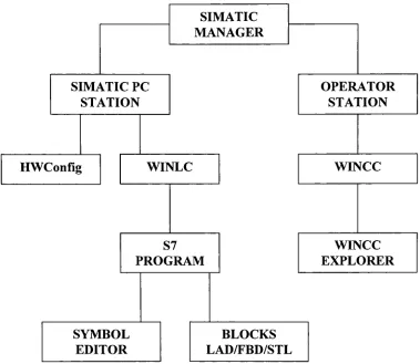
we shall discuss the general architecture oftheprojects usedinthe Siemens' PC basedautomationtechnology. We shall present an overview of the project structure anddiscussthemainelements ofthestructurein detail. The main elementsinthis architecture are theSIMATICManager,
theHardware configuration, the Organizationblocks,
the symbols table, the operator stations, WINCCExplorer,
and theWINLC,
whichisthePC-basedlogiccontrollerinthefamily
ofS7controllers.Weshalldiscusstheseelementsin briefand also discussthe variousprogramming languagesavailable inthe Simatic Automation System environment.4.2 The
General Architecture
oftheSimatic Automation System
The Simatic Automation system is a range of coordinated components with uniform methods of
configuring,datamanagement anddatatransmission.[l]
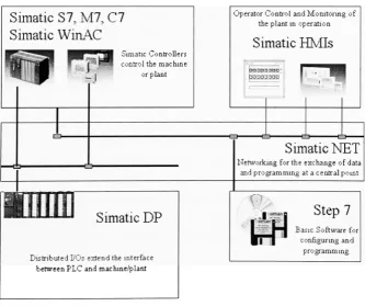
4.2.1 Various Components/Generalarchitecture oftheSimatic Automation System
Simatic
S7, M7,
C7
Simatic
WinAC
Simatic Controllers
controlthemachine or plant
ttLi
Simatic
DP
DistributedBOsextendtheinterface between PLCandmachine/plant
Operator ControlandMonitoringof
theplant in operation
Simatic HMIs
==>
Simatic NET
Networkingfortheexchange ofdataandprogrammingat a central point
Step
7
BasicSoftwarefoiconfiguringand
programming.
[image:37.545.110.444.397.676.2]TheentireSimatic Automationsystem consists offivemajorcomponents,viz.
Simatic Controllers
SimaticDistributed I/Os
(DP)
Simatic HMI
SimaticNET
Step7
The Simatic Controllers control the machine or the plant. The Simatic Distributed I/Os provide the
interface between the PLC and the machine or plant
being
controlled. Simatic NET provides thenetworkingfortheexchange ofdata andprogrammingat a central point. Simatic HMIsare usedforthe
operator control andmonitoringoftheplantinoperation.
Finally,
Step
7isthe centraldevelopmenttoolintheSimatic Automationsystem,consistingof thebasicsoftwarefor configuringand programming.
4.3 Simatic Controllers
[1'Simatic Controllers formthecore of the automation system and
help
in controllingproductionmachines,manufacturingplants orindustrialprocesses.
There are three main families of controllers in the Simatic Automation
System,
viz. Simatic S7controllers,Simatic M7controllers andtheSimatic C7controllers
Simatic S7 programmable logic controllers form thebasis ofthe automation system. There are three
typesofPLCs inthis
family,
S7-200 Micro
PLC,
S7-300modular mini
PLC,
for low-endan mid-range applicationsS7-400 forhigh-endtop-levelperformance requirements
PLCs consist ofthe CPU (central processing unit) and the I/O modules. The CPU stores the user
program writtenin one ofthePLC programming languages. The I/Omodules providetheconnectionto
themachineortheplanttobecontrolled.
The M7 familiesof controllers areAT-compatiblecomputermodules,which expandtheSimaticsystem
by
providingan open software platformforstandard software products.The C7 complete units are designed for machine control and offer PLC performance in a co