UNIVERSITI TEKNIKAL MALAYSIA MELAKA
NOVEL CONCEPTUAL DESIGN AND SIMULATION OF REAR
PRESSURE DIFFERENT AIR FLOW CORRECTION DEVICE
USING COMPUTATIONAL FLUID DYNAMIC (CFD)
SIMULATION
This report submitted in accordance with requirement of the Universiti Teknikal Malaysia Melaka (UTeM) for the Bachelor’s Degree in Mechanical Engineering
Technology (Automotive Technology) with Honours
by
MUHAMMAD FARIDHWAN BIN SHOFRI B071210030
930121-02-5353
NOVEL CONCEPTUAL DESIGN AND SIMULATION OF REAR
PRESSURE DIFFERENT AIR FLOW CORRECTION DEVICE USING
COMPUTATIONAL FLUID DYNAMIC (CFD) SIMULATION
MUHAMMAD FARIDHWAN BIN SHOFRI
A thesis submittedin fulfilment of the requirements for the degree of Mechanical Engineering Technology (Automotive Technology) with Honours
Faculty of Engineering Technology
UNIVERSITI TEKNIKAL MALAYSIA MELAKA
DECLARATION
I hereby, declared this report entitled “Novel Conceptual Design and Simulation of Pressure Different Air Flow Correction Device Using Computational Fluid Dynamic
(CFD) Simulation” is the results of my own research except as cited in references.
APPROVAL
This report is submitted to the Faculty of Engineering Technology of UTeM as a partial fulfillment of the requirements for the degree of Bachelor of Engineering Technology Mechanical Engineering Technology (Automotive Technology) with Honours. The member of the supervisory is as follow:
i
ABSTRAK
ii
ABSTRACT
iii
DEDICATION
This thesis is dedicated to my treasured father Mr. Shofri bin Abdullah, my beloved mother Mrs. Badariah binti Mohamed Kari and my benevolent brother Muhammad
iv
ACKNOWLEDGEMENT
Bismillahirrahmanirrahim. In the name of Allah the Beneficent, the Merciful.
First and foremost, special thanks to my benevolent parents Mr. Shofri Abdullah and Mrs. Badariah Mohamed Kari for their love and support throughout my life. Not to forget, my elder brother Muhammad Firdaus Shofri who always support me, take care of me motivated me and inspire me. My small humble family have granted me strength, passion, and sprits to perform at my best and pursuit my visions and goals. I would like to acknowledge my supervisor, Engr. Mohd Faruq bin Abdul Latif, for trust and confidence granted to me for conducting this plus his comprehensive guidance and support throughout this study. I would also like to thank my co. supervisor, Engr. Mohd Suffian bin Ab Razak. His comments and lessons were very beneficial in order for me to complete this thesis and conduct this study. I learned from his insight a lot. I was grateful for the discussion and clarification made with him. Also, I would like to thank my thesis examiners Engr. Luqman Hakim bin Hamzah and Engr. Saiful Naim bin Sulaiman for their time and effort to examine my thesis and evaluate my presentation.
v
TABLE OF CONTENTS
ABSTRAK i
ABSTRACT ii
DEDICATION iii
ACKNOWLEDGEMENT iv
TABLE OF CONTENTS v
LIST OF FIGURES vii
LIST OF TABLE x
LIST OF ABBREVIATIONS, SYMBOLS AND NOMENCLATURE xi
CHAPTER 1 1
INTRODUCTION 1
1.1 Background 1
1.2 Problem Statement 2
1.3 Objective 3
1.3 Scope 3
CHAPTER 2 4
LITERATURE REVIEW 4
2.1 Introduction 4
2.2 Vehicle Aerodynamic 12
2.3 Case Study 36
2.4 Methodology 39
CHAPTER 3 47
METHODOLOGY 47
vi
3.2 Pre-processing Configuration 50
3.3 Setup configuration 53
3.4 Numerical Method Configuration 62
CHAPTER 4 68
RESULTS 68
4.1 Iteration Convergence 68
4.2 Pressure Contour 70
4.3 Velocity Contour 72
4.4 Streamlines 74
4.6 Velocity vector 76
4.7 Pressure coefficient at the Rear of the Body 80
CHAPTER 5 84
DISCUSSION 84
5.1 Iteration Convergence 84
5.2 Model Selection 85
5.2 Benchmark 91
5.3 model 1 91
5.4 model 2 92
5.5 model 3 93
5.6 model 4 93
5.7 model 5 94
CHAPTER 6 95
CONCLUSION AND RECOMMENDATION 95
6.1 Conclusion 96
6.2 Recommendation 96
REFFERENCES 97
vii
LIST OF FIGURES
2.1 K-Chart 4
2.1.3.1 Internal Aerodynamic Airflow 9
2.1.3.2 External Aerodynamic Airflow 10
2.2 vehicle aerodynamic 11
2.2.1 Illustration of flow velocity and stream lines 13
2.2.2a example of streamline body 14
2.2.2b example of bluff body 14
2.2.2.1a Ahmed body Computer-aided Design (CAD) 3D drawing 16
2.2.2.1b Ahmed body isometric (CAD) drawing 16
2.2.2.1c Ahmed body dimensions 17
2.2.2.1.2 results of (Franck et al., 2009) experiment 19
2.2.3.1 Aerodynamic drag versus Rolling resistance for a truck with a CD of 0.5,
frontal area = 10.2m2 and a rolling resistance coefficient set to 0.005
21
2.2.4.1.1 examples of interior computational fluid dynamic 29
2.2.4.1.2 examples of exterior computational fluid dynamic (CFD) 30
2.2.4.2 wind tunnel section 31
2.2.4.2.1 wind tunnel with moving ground 32
2.2.4.2.2 static ground wind tunnel 33
2.3.1 Distribution of deviations of analytical results from CFD 35
3 methodology flowchart 46
3.1 Ahmed body benchmark design 47
3.3.1 Solver setting 51
3.3.2 Viscous model configurations 52
3.3.3 Boundary condition assigned 53
3.3.4 Ahmed body zone settings 53
3.3.5 Pressure Outlet settings 54
3.3.6 velocity inlet settings 55
3.3.7 Road settings 56
3.3.8 Reference value 57
viii
3.3.10 Solution method for the 200 to 600 iterations 58
3.3.11 Solution controls for the first 100 iterations 59
3.3.12 Solution controls for the 200 to 600 iterations 59
3.4a geometrical characteristics of the venturi nozzle at the underbody level 60
3.4b geometrical characteristics of the Venturi underbody nozzle 62
4.1.1 Drag coefficient (Cd) vs Iterations 66
4.1.2 Lift Coefficient vs Iterations 67
4.2.1 pressure contour of benchmark model 68
4.2.2 pressure contour of model 1 68
4.2.3 pressure contour of model 2 68
4.2.4 pressure contour of model 3 69
4.2.5 pressure contour of model 4 69
4.2.6 pressure contour of model 5 69
4.3.1 velocity contour of benchmark model 70
4.3.2 velocity contour of model 1 70
4.3.3 velocity contour of model 2 60
4.3.4 velocity contour of model 3 71
4.3.5 velocity contour of model 4 71
4.3.6 velocity contour of model 5 71
4.4.1 velocity streamlines of benchmark model 72
4.4.2 velocity streamlines of model 1 72
4.4.3 velocity streamlines of model 2 72
4.4.4 velocity streamlines of model 3 73
4.4.5 velocity streamlines of model 4 73
4.4.6 velocity streamlines of model 5 73
4.6.1 velocity vector of benchmark model 74
4.6.2 velocity vector of model 1 75
4.6.3 velocity vector of model 2 75
4.6.4 velocity vector of model 3 76
4.6.5 velocity vector of model 4 76
4.6.6 velocity vector of model 5 77
4.7.1 Pressure coefficient at the rear of benchmark model 78
4.7.2 Pressure coefficient at the rear of model 1 78
4.7.3 Pressure coefficient at the rear of model 2 79
ix
4.7.5 Pressure coefficient at the rear of model 4 80
4.7.6 Pressure coefficient at the rear of model 5 80
4.7.7 Pressure Coefficient at Rear Bodies 81
5.2.1 Model and Dimension of Model 1 83
5.2.2 Model and dimensions of model 2 84
5.2.3 Model and dimensions of model 3 85
5.2.4 Model and dimensions of model 4 86
x
LIST OF TABLE
3.2.1 General mesh sizing 49
3.2.2 Mesh sizing of Ahmed body tires surface 49
3.3.3 Mesh sizing of Ahmed body surface 50
3.3.4 Mesh sizing of refinement zone 50
3.2.5 Inflation mesh layer at ground surface and outer body surfaces. 51
4.1.1 Converged drag coefficient (Cd) 68
xi
LIST OF
ABBREVIATIONS, SYMBOLS AND
NOMENCLATURE
A - Area
B - Base (width)
BC - Before Christ
C - Specific heat
CAD - Computer-aided Design
CAE - Computer-aided engineering
CATIA - Computer Aided Three-dimensional Interactive Application
CD - Coefficient of drag
CFD - Computational fluid dynamic
CL - Coefficient of lift
Cp - Coefficient of pressure
𝐶𝐷𝑈 - Underbody drag coefficient
𝐷 - aerodynamic loads
𝐷𝑒𝑥𝑡 - Drag due to the airflow on external upper surfaces of the vehicle
DNS - Direct Numerical Simulation
dm - mass of fluid
𝐷𝑢𝑏 - Drag due to the vehicle under the body flow
d x - Element area
d y - Force on a side due to pressure
dv - elemental volume
𝑓 - Particle distribution function
FEM - Finite element method
FVM - Finite volume method
H - Height
k - Boltzmann constant
𝑘 - Kinetic energy turbulence per unit mass
𝑘 − 𝜔 - k–omega turbulence model 𝑘 − 𝜀 - K-epsilon turbulence model
xii
KE - Kinetic energy
𝐾𝑄 - Coefficient that express the contribution of the flow rate of
underbody on flow rate of total body
L - Length
𝐿 - Lift load
LBM - Lattice Boltzmann method
LES - Large Eddy Simulation
m - mass
𝑛𝑖 - Equilibrium value for the population of particles
𝑛𝑖𝐸𝑄 - Local equilibrium value for the population of particles in the direction
p - pressure
∆𝑝𝑡𝑜𝑡 - The total pressure variation
𝑝𝑑𝑦𝑛∞ - Dynamic pressure reference
𝑄𝑒𝑥𝑡 - Volume of air that enveloping the external upper surfaces of the
vehicle
𝑄𝑢𝑏 - Volume of air that enveloping the body flow of the vehicle
RANS - Equations such as Reynolds Averaged Navier Stokes
SST - Shear Stress Transport
T - Temperature
t - Time
u - Initial velocity
𝑢�⃗ - Particle velocity
V - Volume
v - Velocity
𝑣𝑖 - 𝑖P
th component of the averaged air velocity
𝑣𝑗 - 𝑗P
th component of the averaged air velocity
𝑣′𝑖,𝑣′𝑗 - Fluctuating velocity parts
VWT - Virtual Wind Tunnel
𝑣′𝚤𝑣′𝚥
������� - Reynolds stress turbulent tensor
𝑣∞ - Free stream velocity
w - Velocity in opposite direction (-v)
x - Direction of x-axis
𝑥𝑖,𝑥𝑗,𝑥𝑘 - Cartesian coordinates
y - Direction of y-axis
xiii
α - Slant angle
Ω - Collision operator
ρ - density
𝜌∞ - Density of air free stream
ζ𝑑 - Aerodynamic resistance coefficient of diffuser.
ζ𝑖 - Aerodynamic resistance coefficient of the inlet section
ζ𝑚 - Aerodynamic resistance coefficient of middle section
ζ𝑢𝑏 - Equivalent aerodynamic resistance coefficient of the nozzle
𝜏 - Relaxation time
𝜇𝑡 - Viscosity of turbulent
𝜇∞ - Dynamic viscosity of air free stream
1
CHAPTER 1
INTRODUCTION
1.1 Background
Reducing fuel consumption and emissions is one of the most important environmental issues within the automotive industry. With the continuous increment of fuel price, automotive companies have to compete with each other and constantly developing methods to improve fuel efficiency. The fuel consumption reduction can be achieved by improving efficiency of the engine, reducing drag pressure resistance and improving aerodynamics (Håkansson & Lenngren, 2010; Wojciak, 2012).
Aerodynamic drag consists of two main components that is skin friction drag and pressure drag. Pressure drag contribute more than 80% of the total drag and it is highly dependent on vehicle geometry due to boundary layer separation and formation of wake region behind the vehicle (Sudin & Abdullah, 2014).
2 1.2 Problem Statement
Bluff body car segment such as suburban utility vehicle (SUV), multi-purpose vehicle (MPV), van, hatchback, and station wagon produce high pressure drag especially at the rear of the vehicle. Drag caused by this rear end pressure contribute largest fuel consumption (Baltas & Saridakis, 2009; Gilliéron & Kourta, 2013; Steininger, Vogl, & Zettl, 1996).
researcher discover and study a lot of method to reduce drag caused by pressure different between front and rear of the vehicle including study of rear spoiler by (Sapienza, 2002; Sudin & Abdullah, 2014), study of bumper by (Håkansson & Lenngren, 2010; Huminic, Huminic, & Soica, 2012; Sapienza, 2002; Sudin & Abdullah, 2014), and study of diffuser by(Sudin & Abdullah, 2014; Thuwis, De Breuker, Abdalla, & Gürdal, 2010).
Current research focus on shape minimizing to increase the pressure at the rear of the vehicle hence reduce the pressure different between front and rear of the vehicle(Loth, 2008; Tran-Cong, Gay, & Michaelides, 2004).
But yet, there are no effort putted to study about rear suction air flow correction device in order to increase the back pressure and reduce the pressure different between front and rear of the car.
Hence, this study is conduct to introduce rear suction air flow correction device to increase the back pressure and reduce drag caused by pressure differential.
The introduction of the rear suction air flow correction device hopefully will reduce drag coefficient (CD). Hence, with full of positive expectation, hopefully this method of reducing drag by using rear suction air flow correction device will be broadly used for bluff body car segments for entire world and the trend change toward further study of this concept.
3 1.3 Objective
1. To design a concept of drag reduction system that can change the pressure distribution of bluff body.
2. To reduce the drag coefficient of bluff body.
1.3 Scope
This project does not consider any costs of either implementation of the devices or production of the devices. Applicability and selection of material are not discussed. The devices are only aerodynamically evaluated and furthermore, no consideration is taken to legislate about the dimensions of the Ahmed body with added devices. Due to time limitation only a restricted number of devices are tested and evaluated to verify their efficiency. Devices optimization of is not included in this study. The devices are added on a standard Ahmed body model. No modifications are done on the Ahmed body. The CFD settings used in this study such as density of air, Specific heat (C), air viscosity, temperature and humidity are referred to the local standard and evaluation of how different settings would affect the result is not included in this project. The velocity of air used are fixed and the different velocity effect on the drag coefficient (CD) will not be presented. The study will only show the effect of the pressure different rear suction air flow correction device to the drag coefficient (CD) and the unimplemented pressure different rear pressure air flow correction device Ahmed body to the drag coefficient (CD). Equations such as Reynolds Averaged Navier Stokes (RANS), Large Eddy Simulation (LES), Direct Numerical Simulation (DNS) and Lattice Boltzmann method (LBM) with 𝑘 − 𝜔 near-wall region model
4
CHAPTER 2
LITERATURE REVIEW
2.1 Introduction
Literature review purpose for this study is to review other research related to the study conducted in order to get the right idea and concept. Literature review also use in this study to obtain problem statement and to obtained best and suitable methodology.
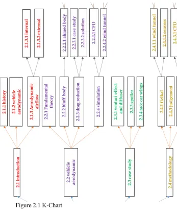
The literature review flow of this study was illustrate in the k-chart in figure 1. It starts with introduction which consist of brief history of computational fluid dynamic (CFD) and brief history of aerodynamic. Then it is followed by the overview of vehicle aerodynamic and aerodynamic airflow which consist of brief outline of internal and external aerodynamic.
The study then converging to vehicle aerodynamic. Fundamental theory was studied thoroughly. The study converge even more from vehicle to bluff body to Ahmed body. The study of drag reduction, simulation and wind tunnel were reviewed to enhance the factual knowledge.
Some case study were conduct in order to grasp others drag reduction device theory and fundamental. The case studies revised are venturi effect and diffuser by (Huminic et al., 2012), spoiler by (Hu & Wong, 2011), and race car wings by (Yang, Gu, & Li, 2011).
Methodologies were studied to obtain the best way to conduct the experiment. The methodologies considered and studied for this study are physical, wind tunnel, and simulation. Judgement were made based on the comprehensive studies of various
5
Figure 2.1 K-Chart
2.1.1 History
6
Irrotationality 𝜕𝑢𝜕𝑦+𝑑𝑤𝑑𝑥 = 0 (1)
Mass conservation 𝑑𝑢𝑑𝑥−𝑑𝑤𝑑𝑦 = 0 (2)
Where w = -v v in the direction of y u in the direction of x
The "irrotationality" refers to the assumption that the flow is an irrotational flow field and "mass conservation" is the mathematical expression of the physical assumption of energy conservation that mass is neither created nor destroyed (R. R. Cosner & Roetman, 2000; Darrigol & Frisch, 2008; Grimberg, Pauls, & Frisch, 2008).
The Cauchy-Riemann Equations discovered in 1900s. The mathematics community had ample confidence in their understanding of the theory of complex analytic functions that they could and did publish books for the technical world. The work of Riemann and followers on conformal mappings with singularities provides a method of solving the Cauchy-Riemann equations in multi-connected domains. The development continue with ideal two-dimensional flow around bodies using the Schwarz-Christoffel formula. Further study realised the necessity for a singular source term (vortex singularity) related to circulation to make the description of two-dimensional, constant-density flow around a figure with a pointed trailing edge physically reasonable (Bergonio, n.d.; Cochran, Kanso, & Krstic, 2009; R. R. Cosner & Roetman, 2000; Costamagna, Elettronica, Via, & Piazza, 1998; Tan, 2013).
7
With desired properties, the methods continue to be useful today. Discussion of design optimization using inverse complex analytic function theory can be found in quite recent literature (Jameson, 1988).
These developments led to great numbers of calculations generating tables of data and analogous graphs. The massive number of required calculations motivated theoretical studies in the aerodynamics community to develop scaling methods to extend the applicability of the tables. The limitations and difficulties of the analysis trigger stimulus to a parallel development of wind tunnels(R. R. Cosner & Roetman, 2000). Again the limitations of the calculation devices and expenses for construction and maintenance generate numerous further studies dedicated to understanding fluid dynamics in order to make the necessary corrections to the data obtained from the wind tunnels and to improve the wind tunnel designs (R. R. Cosner & Roetman, 2000).
Aerodynamics is studies that concerned with the motion of air. Aerodynamic is one of a gas and fluid dynamics sub-field, and the "aerodynamics" term is generally referring to gas dynamics (Anderson & Jr, 2009; Anderson, 1991).
Early track of aerodynamics fundamental concepts date back to the Archimedes and Aristotle work in the 2nd and 3rd centuries BC, but the efforts to develop a quantitative air flow theory does not rise until the 18th century. When Sir Isaac Newton developed a theory of air resistance in 1726, he became one of the first aerodynamicists in the modern era, which was then verified for low speeds flow. Throughout the 18th and 19th centuries, experiments of air resistance were performed by investigators which aided by the first wind tunnel construction in 1871. By the year of 1738 Daniel Bernoulli described a fundamental relationship between pressure, velocity, and density in his publication, Hydrodynamica. Until now, Bernoulli's principle, are widely use which is a method of lift calculation (Anderson & Jr, 2009; Anderson, 1991).