UNIVERSITI TEKNIKAL MALAYSIA MELAKA
DESIGN AND DEVELOPMENT OF CAR ALARM SYSTEM USING
SMS BASED
This report is submitted in accordance with the requirement of the Universiti Teknikal Malaysia Melaka (UTeM) for the Bachelor of Mechanical Engineering Technology
(Automotive Technology) with Honors.
by
MUHAMMAD AIMMAN BIN AMRAN
B071410427
950501-05-5165
DECLARATION
I hereby, declared this report entitled “Design and Development of a Car Alarm System Using SMS Based” is the results of my own research except as cited in references.
Signature : ………
Author’s Name : ………
APPROVAL
This report is submitted to the Faculty of Engineering Technology of UTeM as a partial fulfillment of the requirements for the degree of Bachelor of Mechanical Engineering Technology (Automotive Technology) with Honors. The member of the supervisory is as follow:
i
ABSTRAK
ii
ABSTRACT
iii
DEDICATION
I would like to say that I am grateful for all the support my parents had given me until now. To my beloved mother and father,
iv
ACKNOWLEDGEMENT
I would like to thank my supervisor, Madam Nurul Amira binti Zainal for her guidance, support, constant encouragement and patience towards myself during my bachelor degree project at Universiti Malaysia Melaka (UTeM).
v
TABLE OF CONTENTS
ABSTRAK ... i
ABSTRACT ... ii
DEDICATION ... iii
ACKNOWLEDGEMENT ... iv
TABLE OF CONTENTS ... v
LIST OF FIGURES ... viii
CHAPTER 1 ... 1
INTRODUCTION ... 1
1.0 Introduction ... 1
1.1 Background Study ... 1
1.2 Problem Statement ... 3
1.3 Objectives ... 3
1.4 Work Scope ... 4
CHAPTER 2 ... 5
LITERATURE REVIEW ... 5
2.0 Introduction ... 5
2.1 History of Alarm System ... 5
2.1.1 The History of Car Alarm System ... 8
2.2 Type of Security System ... 10
2.2.1 Home Security System ... 10
2.2.2 Car Security System ... 12
2.3 GSM Siemens TC35 SMS Wireless Module ... 14
2.4 Arduino ... 17
2.4.1 History of Arduino ... 21
2.4.2 Mini Arduino ... 22
vi
CHAPTER 3 ... 27
METHODOLOGY ... 27
3.0 Introduction ... 27
3.1 Product Design Specification ... 27
3.2 Material Selection ... 28
3.2.1 Polylactic Acid (PLA) ... 28
3.2.2 Nylon ... 28
3.2.3 Acrylonitrile butadiene styrene (ABS)... 29
3.2.4 Material Benchmark ... 29
3.3 Design Process ... 29
3.3.1 Conceptual Design ... 30
3.3.2 Preliminary Design... 30
3.4 Software Tool ... 31
3.4.1 Computer Aided Three-dimensional Interactive Application (CATIA) .. 31
3.4.2 Arduino Integrated Development Environment (IDE) ... 32
3.5 Detailed Design ... 33
3.7 Testing ... 33
CHAPTER 4 ... 34
RESULT AND DISCUSSION ... 34
4.0 Introduction ... 34
4.1 Main Components ... 34
4.2 Coding ... 38
4.3 Wiring Diagram ... 41
4.4 Preliminary Design ... 44
4.6 Detailed Design... 46
4.7 Testing ... 47
CHAPTER 5 ... 50
CONCLUSION AND FUTURE WORK ... 50
vii
5.2 Summary ... 50
5.3 Significance of The Project... 51
5.4 Limitation... 51
5.1 Futurework ... 51
REFERENCES ... 52
viii
LIST OF FIGURES
Figure 2.1: Augustus Russell Pope Patent ... 6
Figure 2.2: Holmes’s burglar alarm telegraph ... 7
Figure 2.3: Calahan’s Call Box ... 7
Figure 2.4: Early Car Alarm System ... 9
Figure 2.5: Typical Wired Alarm Layout ... 11
Figure 2.6: Typical Car Alarm System ... 13
Figure 2.7: Siemens GSM TC35 Module ... 15
Figure 2.8: GSM Module Layout ... 16
Figure 2.9: Arduino Board ... 18
Figure 2.10: ATmega 168 ... 20
Figure 2.11: Mini Arduino ... 23
Figure 2.12: Mini Arduino Circuit Layout ... 23
Figure 2.13: PIR Sensor ... 24
Figure 2.14: IR Sensor ... 25
Figure 2.15: PIR Sensor Lens ... 26
Figure 2.16: PCB Layout of PIR Sensor ... 26
Table 1.1: Material Benchmark... 29
Figure 3.1: Design Flow Chart ... 30
Figure 4.1: DSUN PIR Sensor ... 35
Figure 4.2: TC35 GSM Module ... 36
Figure 4.3: Arduino Nano ... 37
Figure 4.4: Flow Chart For The Program... 39
Figure 4.5: Code Programme ... 40
Figure 4.6: Arduino Nano Pinout ... 41
Figure 4.7: Wiring Diagram ... 43
Figure 4.8: Revision 1 ... 44
Figure 4.9: Revision 2 ... 45
Figure 4.10: Revision 3 ... 45
Figure 4.11: Detailed Design ... 46
Figure 4.12: Arduino Blink Test Schematic ... 47
Figure 4.13: Blink Sketch ... 47
1
CHAPTER 1
INTRODUCTION
1.0 Introduction
This chapter discussed background study of the alarm system, objectives of the study, problem statements, work scope and expected result of this project.
1.1 Background Study
2 In addition to the car theft, hot car deathhas been on the rise in the past year.There were 336 cases involving hot car death from 2010 to 2016 in the US only. In Malaysia, an increase of cases can be identified regarding this problem in the past year. Most of the victim of the hot car death are children. However, the parents are not to blame for negligence. People tend to make mistake. According to an article, the tragedy occurs when the habit memory in the brain which enables people to do repetitive task outperform the prospective memory that controls the planning and execution of an action. The people or specifically the parents just forget about their children in the car with them as they enter the repetitive part of their life such as driving to work. In such case, the brain simply processes the action as a habit and their children with them in the car is not register in their brain as they think that they may already send their children to a nursery.To avoid and reduce this incident from frequently occurring, the alarm system equips with in-car motion sensor can detect any movement within the interior of the car and directly notify the owner using text message.
The product would used an Arduino Nano as the core of the product, a passive infrared motion sensor as known as PIR sensor to detect the motion within the car and a GSM module which is an abbreviation for Global System for Mobile Communication that is needed to send the notification using the text messaging function. These three components are the main component that is vital for the project to be functional. Moreover, the casing for the product is designed with the criteria that it is compact so that it can be installed without interfering the cockpit of the car. The program is written using the Arduino Software before it is uploaded to the Arduino Nano.
3
1.2 Problem Statement
Current car security system is not secure enough. The reason for this is because auto theft prevention only works outside the vehicle. In other words, the current car alarm system only detects if anyone is trying to break into the car from the outside. If the exterior alarm system is nullified, there would no any other alarm system to prevent an auto thief from stealing the car. This shows that once the exterior alarm system is hacked, the thief would have the luxury of stealing the car and the car owner would not be able to do anything. Hence, this project aimed to prevent that. With the installation of the motion sensor, the auto thief would not have free roam once the exterior alarm system is nullified. Also, by connecting the alarm system to an SMS service, the alarm system would be able to notify the car owner as quickly as possible so that countermeasure such as calling the police can be done.
1.3 Objectives
The objectives of this study are:
1. To generate a concept design of car alarm system using SMS based.
4
1.4 Work Scope
5
CHAPTER 2
LITERATURE REVIEW
2.0 Introduction
The purpose of this chapter is to provide the information about the component that were used in the project, the software required, the program involved and the housing design.
2.1 History of Alarm System
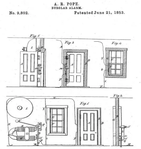
In the early ages, animals were used as a security alarm. Then, in the mid-1700s, an English inventor designed an alarm system using a series of bell and chimes that was connected to a lock. This invention served as a simple way of notifying thehomeowner that the door or window had been opened. In 1853, Augustus Russell Pope designed an alarm system that uses electromagnets as the switch in his system, refer to Figure 2.1. However, most people usually assume Edwin Holmes as the father of modern home alarm system. The reason for this is because Edwin Holmes bought the rights to Pope’s invention and then, managed to spread the benefits and advantages of using his security alarm system to the public, refer to Figure 2.2.
6 made another milestone in the security alarm industry. Apparently, Calahan designed the security alarm to aid his boss when his boss was robbed in his own house. Calahan’s invention worked by notifying the other houses in the area if any of their neighbors’ house was being robbed. His invention also able to distinguish which of the houses in the area is being robbed.
[image:17.612.210.440.361.603.2]After that, Calahan had another idea to improve his security system. Calahan thought that if the security system not only triggers the alarm but can also notify the emergency central station, therefore, increased the speed for the police and fire services to respond, refer to Figure 2.3. During the 1970s, motion sensor was introduced to the security industry. This was to prevent aburglar from having free rein inside the house after breaking in. For the next 40 years, the security industry stayed the same until video monitoring was introduced. These days, home owners can know when people are arriving at their footstep.
7 Figure 2.2: Holmes’s burglar alarm telegraph
Figure 2.3: Calahan’s Call Box
A burglar alarm system comprising detection elements at points of entry adapted to energize a triggering circuit, a housing remote from the detection elements containing energizing elements in connection with said triggering circuit to actuate an alarm circuit, said housing containing a selective circuit and movable axially to close the alarm circuit with the triggering circuit(Henry J. Soltau, 1968).
[image:18.612.250.405.260.391.2]8
2.1.1 The History of Car Alarm System
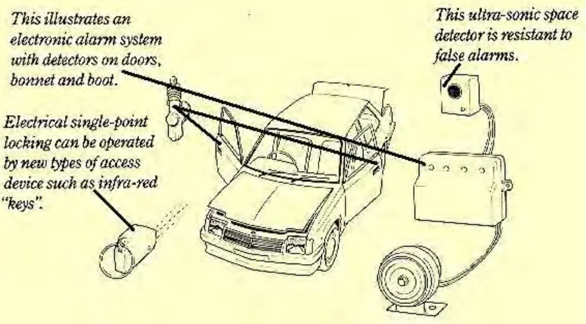
The increased of auto theft in the mid-1970s brought about the rising of third-party security alarm that was implemented in the car. With a wide variety and make for every car model, the third-party security alarm was able to sell very well. This also managed to make the car manufacturer to also invest in research and making a better security alarm for their car. Figure 2.4 shows the early car alarm system.
Car alarm system began with Victor Helman in 1954 who design an innovative system that incorporated a safe resettable control box that was connected to various switches in the car. In the event of breaking in, two electromagnetic solenoids would trigger a siren. The further enhancement was made by John Yurts by adding motion detector so that it can detect even the tiniest movement. Later in 1971, Charles E. Davis solved the issue regarding the battery problem when using the system. To simplify, when using an alarm system, it is either always switches on or when the alarm starts, it would not stop therefore can quickly deplete battery life.
9 Figure 2.4: Early Car Alarm System
A motor vehicle alarm system incorporates 5 integrated circuits mounted on a printed circuit board enclosed within a case. The integrated circuits include a high-speed oscillator as a clock source, a twelve-stage binary counter, a set of flip-flops used as memories, a three input AND gate, and a flip-flop used as the start or stop memory for the clock source. The alarm system becomes armed approximately four minutes and fifteen seconds after the ignition key is turned off. If a door is then opened, the alarm would be actuated unless the ignition switch is turned on within fifteen seconds(Sasaki et al. 1976).
10 Among the various car alarm system available in the market, theGSM-based security systemsare much stouterthan an ordinary security system. The ordinary systems are simply based on the concept of sensors. They sound an alarm on detecting movement. This system of technology has now lost its appeal as it has become a common sighting in metros where these alarms go off unnecessarily(Sehgal et al, 2012).
2.2 Type of Security System
There are several types of security systems. In this section, the type of security system is discussed and investigated.
2.2.1 Home Security System
The fundamental home security framework appeared above is like a portion of the "free" or low estimated alert frameworks that are offered as a motivating force to focus on longer-term observing assertions.
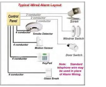
11 Figure 2.5: Typical Wired Alarm Layout
The control board has been midway situated in the lobby storage room giving simple get to and short wire hurries to 120V AC for the low voltage transformer and the phone organization benefit from off-site alert checking. Storm cellars and utility/mechanical rooms are additionally basic areas for the control board.
The single keypad is strategically placed quite recently inside the kitchen/carport entryway. The movement finder is deliberately situated to give scope to the kitchen and eating territories, front room and portions of the corridor and hall.
For this situation, the low voltage transformer that provisions energy to the framework is situated in the storeroom alongside the control board. While by and large situated in closeness to the control, it can be situated in a non-exchanged repository anyplace on the premises.
12 required by FCC Regulations. The RJ31X is generally found in or close to the metal fenced in area lodging the control.
The advent of the information age has changed the way people at home,and people want to have a more secure,convenient,comfortable,and smart home.GSM SMS,which is simple and practical and can be sent remotely through the GSM network,has been widely used in the field of remote control.Thus,to design a smart home system with the way of sending GSM SMS as a remote control mode,in order to improve the quality of people's home (Jia, P. Z. L. X. H., & Shunyan, L. P. C, 2013).
2.2.2 Car Security System
The very meekest alarm would have its siren would start wailing if someone opened the door since a switch would be wired on the driver's door. You could implement this car alarm with a switch, a couple of pieces of wire and a siren.
However, most contemporary car alarm systems are much more sophisticated. They consist of:
• Switches, pressure sensors, and motion detectors.
• A siren.
• A radio receiver to allow wireless control from a key.
• A supplementary battery so that the alarm can operate even if the main battery gets disconnected.
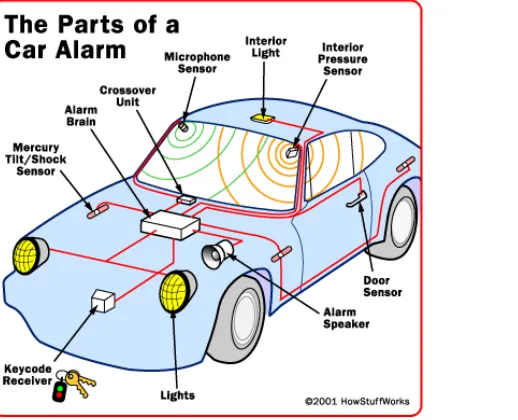
13 In addition, the core and alarm features may be wired to the car's main battery; however, they usually have a secondary power source as well. The secondary battery kicks in when somebody cuts off the main power source for example by clipping the battery cables. Since disturbing the power source is a possible indication of an intruder, it triggers the core to sound the alarm. Figure 2.6 shows the parts of a car alarm system..
Figure 2.6: Typical Car Alarm System
The appearance of automobiles impacts the lives of people. It is becoming the progressive symbol of modern society. Not only the demand for performance and quality of vehicle increase rapidly, but there is also demand on theanti-theft system for avehicle(Cheong En Yi, 2010).