DC Circuits
1st Edition
1
How to navigate this book:
This document contains
bookmark
links, which are links to other locations in this document. These
are not the same as
website links
, which will open up a
webpage in your default browser. If you click on a
bookmark
and want to go back to where you were previously at in the
document, click on
ALT - Left Arrow (
←
)
.
For example:
•
This is a
bookmark
to the References section
References
•
This is a
website link
to the latest version of this book
DC Circuits
Getting the Latest Version of this book:
If you see any errors or
typos please go to my website (
ChadDavis.oucreate.com
) and
enter them in the comments section and I will get the book
updated. Minor changes in the book will not result in a new
version number, but instead will be corrected and uploaded to
the following webpage:
https://shareok.org/handle/11244/52245
If you have any suggestions for significant changes that could
potentially be implemented into a new edition in the future, I
would also appreciate that type of feedback on
my website
.
© Chad Davis, PhD, PE 2016 CC BY-NC-SA
2
Table of Contents
Preface ... 3
Module 1 – The Basics of DC Circuits with Resistors ... 4
Section 1.1 – Introduction and Basic Definitions ... 4
Section 1.1.1 - Charge vs Current ... 4
Section 1.1.2 - Resistance Calculations – (Resistance explained in more detail in section 1.1.3) ... 5
Section 1.1.3 - Ohm’s Law: Voltage, Current, Resistance, and Conductance ... 8
Section 1.1.4 – Power and Energy ... 19
Section 1.2 – Combining Resistors in Parallel or Series ... 23
Section 1.3 – Kirchhoff’s Voltage Law (KVL) and Voltage Divider Rule (VDR)... 29
Section 1.4 – Kirchhoff’s Current Law (KCL) and Current Divider Rule (CDR) ... 35
Module 1 – Equation List ... 42
Module 2 – Advanced Topics for DC Circuits with Resistors ... 43
Section 2.1 – Source Transformations: Thevenin and Norton Form ... 43
Section 2.2 – Approximate Source Transformations: Adding a virtual resistor ... 46
Section 2.2.1 - Voltage Source Approximate Transformation ... 46
Section 2.2.2 - Current Source Approximate Transformation ... 48
Section 2.3 – Mesh Matrix Analysis and traditional loop analysis methods ... 49
Section 2.4 – Nodal Matrix Analysis and traditional Nodal Analysis ... 59
Section 2.5 – Superposition: Solving a circuit by including only one source at a time ... 67
Section 2.6 – Thevenin and Norton Equivalent Circuits ... 77
Module 3 – DC Circuits with Resistors, Capacitors, and Inductors ... 90
Section 3.1 – Background for Capacitors ... 90
Section 3.2 – Background for Inductors ... 98
Section 3.3 – Combining Inductors in Parallel and/or Series ... 103
Section 3.4 – Combining Capacitors in Parallel and/or Series ... 104
Section 3.5 – DC Transient Analysis with RC and RL Circuits ... 109
Section 3.5.1 – Single Loop RL and RC Charging (Store) Circuits ... 109
Section 3.5.2 – Single Loop RL and RC Discharging (Release) Circuits ... 120
Section 3.6 – DC Steady State Analysis with RC, RL, and RLC Circuits ... 123
Section 3.7 – Introduction to Passive Filters ... 127
Module 3 – Equation List ... 129
References and Links ... 130
3
Preface
4
Module 1 – The Basics of DC Circuits with Resistors
Module 1 is broken up into the following 4 sections.• Section 1.1 – Introduction and Basic Definitions
• Section 1.2 – Combining Resistors in Parallel or Series
• Section 1.3 – Kirchhoff’s Voltage Law (KVL) and Voltage Divider Rule (VDR)
• Section 1.4 – Kirchhoff’s Current Law (KCL) and Current Divider Rule (CDR)
Section 1.1 – Introduction and Basic Definitions
A brief overview of basic electrical terms and equations is given in this section. Electrical background information is taught in detail in PHYS 2524 at OU. The following link is a good reference eBook if more background information is needed. http://www.allaboutcircuits.com/textbook/direct-current/
There are also many hyperlinks in this document to get more information about important topics. For Example, if you click on the SPST link in Example 1.1 it will take you to a good tutorial about switches.
Section 1.1.1 - Charge vs Current
The following equation relates charge to current.
[1.1]
𝐼𝐼
=
𝑄𝑄𝑡𝑡I = Current (units = Amps)
Q = Charge (units = Coulombs or C) t = time (units = seconds or sec)
Important Conversion: 1 Coulomb = 6.242 ∙ 1018 electrons
Note: “Hole Flow” for current will be assumed in this course, which means current flows in the opposite direction as electrons. More info about hole vs electron flow can be found at the following link: http://www.allaboutcircuits.com/textbook/semiconductors/chpt-2/electrons-and-holes/
We will mainly deal with current (instead of charge) in this book, but simple conversions from Amps to Coulombs and/or Electrons (like that demonstrated in example 1.1) is an important thing to learn. Example 1.1) If a Single-Pole, Single-Throw (SPST) switch is flipped in the
circuit in Figure 1.1 causing a voltage difference that results in a current of 2 amps, determine the number of Coulombs and the number of electrons that travel through the circuit after 4.3 minutes have elapsed.
Answer: 𝐼𝐼= 2 𝐴𝐴= 4.3 min∗60 𝑠𝑠𝑠𝑠𝑠𝑠/𝑚𝑚𝑚𝑚𝑚𝑚𝑄𝑄 → 𝑄𝑄=𝟓𝟓𝟓𝟓𝟓𝟓𝑪𝑪
5
Section 1.1.2 - Resistance Calculations – (Resistance explained in more detail in
section 1.1.3
)
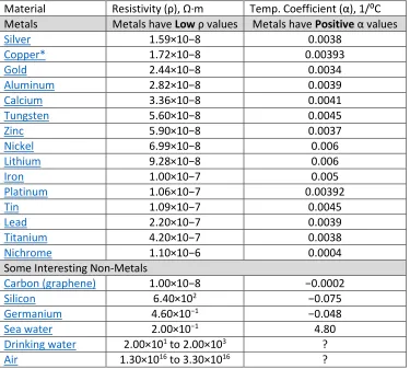
The resistance of an element is determined from the resistivity (ρ), length (L), and cross-sectional area (see equation 1.2). The units of L and A depend on the units of the resistivity (ρ). There are different
units commonly used for ρ, but in this class we will only use the units shown in the Table 1.1 (Ω∙meters).
If Ω∙m is used as the units for resistivity then the units for length and area in equation 1.2 are meters and meters squared respectively. The temperature also affects the resistance as shown in equation 1.3.
[1.2]
𝑅𝑅
=
𝜌𝜌𝐴𝐴𝐿𝐿[1.3]
𝑅𝑅
𝑥𝑥=
𝑅𝑅
200𝐶𝐶[1 +
𝛼𝛼
(
𝑇𝑇
𝑥𝑥−
𝑇𝑇
200𝐶𝐶)]
Table 1.1) Table of Resistivity and Temperature Coefficients at 20⁰ C Source: https://en.wikipedia.org/wiki/Electrical_resistivity_and_conductivity
Material Resistivity (ρ), Ω∙m Temp. Coefficient (α), 1/⁰C Metals Metals have Low ρ values Metals have Positive α values
Silver 1.59×10⁻⁸ 0.0038
Copper* 1.72×10⁻⁸ 0.00393
Gold 2.44×10⁻⁸ 0.0034
Aluminum 2.82×10⁻⁸ 0.0039
Calcium 3.36×10⁻⁸ 0.0041
Tungsten 5.60×10⁻⁸ 0.0045
Zinc 5.90×10⁻⁸ 0.0037
Nickel 6.99×10⁻⁸ 0.006
Lithium 9.28×10⁻⁸ 0.006
Iron 1.00×10⁻⁷ 0.005
Platinum 1.06×10⁻⁷ 0.00392
Tin 1.09×10⁻⁷ 0.0045
Lead 2.20×10⁻⁷ 0.0039
Titanium 4.20×10⁻⁷ 0.0038
Nichrome 1.10×10⁻⁶ 0.0004
Some Interesting Non-Metals
Carbon (graphene) 1.00×10⁻⁸ −0.0002
Silicon 6.40×10² −0.075
Germanium 4.60×10⁻¹ −0.048
Sea water 2.00×10⁻¹ 4.80
Drinking water 2.00×101 to 2.00×10³ ?
Air 1.30×10¹⁶ to 3.30×10¹⁶ ?
[image:6.612.74.449.232.569.2]6
Example 1.2) what is the resistance of a 1,000 meters of 3 mm diameter copper wire at 30 ⁰C?
Answer: Solve this as a 2-part problem: 1) Find the resistance at 20⁰ C. 2) scale the resistance to 30⁰ C.
𝑅𝑅
200𝐶𝐶=
𝜌𝜌𝐿𝐿𝐴𝐴
=
(1.72×10⁻⁸ Ω∙m)∙(1000 m)
𝜋𝜋
4∙ (3 𝑚𝑚𝑚𝑚 ∙ 1 𝑚𝑚
1000 𝑚𝑚𝑚𝑚)
2 = 𝟐𝟐.𝟒𝟒𝟑𝟑𝟑𝟑Ω
𝑅𝑅
𝑥𝑥=
𝑅𝑅
300𝐶𝐶=
𝑅𝑅
200𝐶𝐶[1 +
𝛼𝛼
(
𝑇𝑇
𝑥𝑥−
𝑇𝑇
200𝐶𝐶)] =
𝟐𝟐.𝟒𝟒𝟑𝟑𝟑𝟑∙
[1 + 0.00393 (30
−
20)] =
𝟐𝟐
.
𝟓𝟓𝟐𝟐𝟓𝟓
Ω
Resistance is frequently calculated for wire (which has a circular cross-section) because the amount of resistance will affect how much voltage drops across the length of the wire. A common way to classify the size of wire is with the American Wire Gauge (AWG) standard. Table 1.2 shows the diameter of the metal conductor (the plastic shield is not included in the diameter) and typical ampacity ratings for common AWG sizes. Ampacity is a term used to determine how much current the wire can carry before the plastic shield begins to break down. For example, if you connect 20 AWG wire across a 12 V car battery with no resistors you will see in rapid succession the plastic shield heat up, glow orange, and the wire eventually disintegrate or set something close to it on fire. This is obviously not a wise or safe thing to do, but a good illustration of why selecting the correct size of wire for the application is important. Table 1.2) American Standard Wire Gauge (AWG)
Source: https://en.wikipedia.org/wiki/American_wire_gauge AWG Diameter (mm) Copper Ampacity (Amps)
0000 (4/0) 11.684 195
000 (3/0) 10.405 165
00 (2/0) 9.266 145
0 (1/0) 8.251 125
1 7.348 110
2 6.544 95
3 5.827 85
4 5.189 70
6 4.115 55
8 3.264 40
10 2.588 30
12 2.053 20
14 1.628 15
18 1.024 16
20 0.812 11
22 0.644 7
24 0.511 3.5
26 0.405 2.2
28 0.321 1.4
7
most home circuit breakers. If the current in a 12 AWG wire reaches 20 Amps in a circuit that has a 20 Amp circuit breaker, then the breaker will flip and cut off the current before the 12 AWG wire breaks down. If you wanted to be extra safe you could use thicker wire such as 10 AWG that has an ampacity of 30 Amps according to Table 1.2.
Example 1.3) how much 10 AWG copper wire is needed if you want to have a resistance of 3 Ω at -40 ⁰C?
Answer: The first step would be to scale the resistance value from -40⁰ C to +20⁰ C using equation 1.3.
𝑅𝑅
𝑥𝑥=
3Ω
=
𝑅𝑅
200𝐶𝐶[1 +
𝛼𝛼
(
𝑇𝑇
𝑥𝑥−
𝑇𝑇
200𝐶𝐶)] =
𝑅𝑅
200𝐶𝐶[1 + .00393 (
−
40
−
20)]
→ 𝑅𝑅
200𝐶𝐶=
3.93
Ω
Now you know that the copper wire has a resistance of 3Ω at -40ºC and a resistance of 3.93 Ω at 20ºC.
In order to use equation 1.1, the resistance must be at 20⁰ C since that is the temperature Table 1.1 gives the resistivity value at. From Table 1.2, 10 AWG has a diameter of 2.588 mm, so the resistance is:
𝑅𝑅
200𝐶𝐶=
3.93
Ω
=
𝜌𝜌𝐿𝐿𝐴𝐴
=
(1.72×10⁻⁸ Ω∙m)∙(L))
𝜋𝜋
4∙ (0.002588𝑚𝑚)2
→ 𝐋𝐋
=
𝟓𝟓
,
𝟐𝟐𝟏𝟏𝟏𝟏
𝐦𝐦
Another resistance calculation you might face is from a geometry that is not circular. You might want to find the resistance of a rectangular bus-bar that connects equipment together or much less likely scenario where you have a metal rod with a triangle cross-section. To solve a problem with a non-circular cross-section you just calculate the cross-sectional area and do the rest of the calculations as done in example 1.2.
Example 1.4) what is the resistance of a 1-meter long rectangular gold bar with a width of 5 mm and a
thickness of 1 mm? The temperature is 0 ⁰C.
Answer: Solve this as a 2-part problem: (1) Find the resistance at 20⁰C. (2) scale the resistance to 0⁰C. • The area of the bar is equal to the width times the thickness. A = 0.005 m ∙ 0.001 m = 0.000005 m2
• The resistivity of gold is found to be 2.44E-8 Ω∙m in Table 1.1.
𝑅𝑅
200𝐶𝐶=
𝜌𝜌
𝐿𝐿
𝐴𝐴
=
(2.44 × 10
−
8
Ω ∙
m)
∙
( 1 m)
0.000005
𝑚𝑚
2=
𝟏𝟏
.
𝟏𝟏𝟏𝟏𝟒𝟒𝟎𝟎𝟎𝟎
Ω
𝑅𝑅
𝑥𝑥=
𝑹𝑹
𝟏𝟏𝟏𝟏𝑪𝑪=
𝑅𝑅
200𝐶𝐶[1 +
𝛼𝛼
(
𝑇𝑇
𝑥𝑥−
𝑇𝑇
200𝐶𝐶)] =
𝟏𝟏.𝟏𝟏𝟏𝟏𝟒𝟒𝟎𝟎𝟎𝟎∙[1 + 0.0034 (0
−
20)] =
𝟏𝟏
.
𝟏𝟏𝟏𝟏𝟒𝟒𝟓𝟓𝟓𝟓
Ω
When using AWG tables it is common to see area listed in circular mils (CM). It is also common to see
resistivity given in units of CM∙Ω/ft. For this reason, it is good to understand what mils and circular mils are all about. 1 mil is simply a milli-inch or mathematically 1 mil = 0.001 inches. A mil is a popular term used by machinists so make sure you don’t forget that unit of measure. If you find the area of something with units in mils then the area units would naturally be in mils2 (or usually referred to as squared mils).
For example, if you have a bar with a triangular cross-section with a 0.02 inch base and a 0.1 inch height the area would be:
A = ½ base ∙ height = ½ (.02” ∙ .1”) = .001 in2. In mils lengths, A = ½ (20 mils ∙ 100 mils) = 1000 square mils
8
Example 1.5) how much resistance does 100 feet of a wire with a 0.02 inch diameter have if the
resistivity of the material is equal to 5 CM∙Ω/ft? The temperature of the wire is 20 ⁰C. Note: The resistivity units force you to use CM for the area in this problem.
Answer: The area in CM can be calculated as: A = π4 d2=π
4 (20 mils)2= 314.16 square mils→
𝟒𝟒𝟏𝟏𝟏𝟏𝐂𝐂𝐂𝐂
𝑅𝑅
200𝐶𝐶=
𝜌𝜌𝐿𝐿𝐴𝐴
=
(5 𝐶𝐶𝐶𝐶∙Ω/𝑓𝑓𝑒𝑒)∙( 100 ft)
400 𝐶𝐶𝐶𝐶 =𝟓𝟓.𝟐𝟐𝟓𝟓Ω
Section 1.1.3 - Ohm’s Law: Voltage, Current, Resistance, and Conductance
[1.4]
Voltage = Current
∙
Resistance
or
V = I
∙
R
Ohm’s can also be written in terms of conductance (G), which is the inverse of resistance (G = 1/R).
[1.5]
Current = Voltage
∙
Conductance
or
I = V
∙
G
Base Units: Voltage = Volts (or V), Current = Amps (A), Resistance = Ohms (Ω), Conductance = Siemens (S)
1.1.3a - Resistance
The previous section showed how to calculate resistance, but didn’t explain the theory behind it. Resistance is a quantity that determines how much opposition there is to current flow. Materials with small resistivity values (like conductors) have limited opposition to current flowing through them. Materials are called conductors because they “conduct” or readily allow the transmission of electricity. The opposite of a conductor could be said to be an insulator. These materials strongly oppose the flow of current and therefore have much larger resistivity values than conductors. The plastic coating (or shield) around a metal wire is an example of an insulator. The shield allows the current to flow in the metal conductor and not escape into other materials that the wire might touch.
The fact that conductors (Note: resistors are made from conductive material) have a positive
9
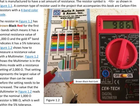
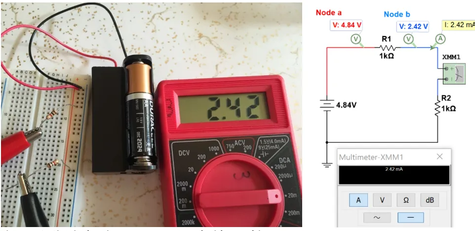
[image:10.612.76.538.89.439.2]In order to get a larger resistance value, using a resistor would be a good idea. A resistor is a component that is manufactured to have a set amount of resistance. The resistor symbol is as shown in Figure 1.1. A common type of resistor used in the project that accompanies this book are Carbon-Film Resistors with a 4-band color
code.
The resistor in Figure 1.2 has Brown-Black-Red for the first 3 bands which means it has a nominal resistance value of 1,000 Ω and the gold 4th band
indicates it has a 5% tolerance. Figure 1.2 shows how to measure a resistance value with a Multimeter. Figure 1.2 shows the Multimeter is in the Ohms mode with a resistance setting of 2,000 Ω. That setting
represents the largest value of resistor than can be read before the setting needs to be increased. The value that the Multimeter in Figure 1.2 reads for the nominal 1,000 Ω resistor is 986 Ω, which is well
within the 5% tolerance.
Resistors also have power ratings, which is the limit of the amount of power (or often referred to simply as heat) it can dissipate before it is damaged. As the current increases, the power also increases (as shown later in equation 1.9) and can result in a damaged component. Therefore, limiting the current in a resistor and determining the power it will dissipate before using it in a circuit is an important thing to do when designing and building circuits. The resistors used in the project in this course have a ¼ watt power rating.
Example 1.6) If the first three bands of a 4-band resistor have a color code Orange-Red-Green and if this resistor is connected to a 9 V battery, determine the following: Nominal resistance value, the total conductance in the circuit, and current through the resistor. Use the value associated with each color band, as shown in Figure 1.2.
Answer: Band 1 = Orange (Value = 3), Band 2 = Red (Value = 2), Band 3 = Green (Multiplier = 100,000) Nominal Resistance Value = 32 * 100,000 = 3,200,000 Ω = 3.2 MΩ
Conductance = G = 1/R = 1/3.2E6 Ω = 0.000003125 Siemens or 0.3125 µS Current = I = V/R = V*G = 9 V * 0.3125 µS = 2.8125 µA
Brown-Black-Red-Gold
10
Note: If you have a voltage with units of Volts (V) and resistor value with units of Ohms (Ω), then current will have units of Amps (A). If the resistor value units are changed to kΩ then the current will have the units of mA. Likewise, if the resistor value units are changed to MΩ then the current will have the units of µA. If you remember these relationships it will save you some time and often results in fewer errors when plugging the numbers into your calculator. For example, if you have a 4.5 V battery connected to a
2 MΩ resistor don’t plug in 2E6 in your calculator just plug in I = 4.5/2 and set the units as µA because
you used units of Volts and MΩ. This might seem like a trivial tip, but not following this method is the
source of a LOT of errors that I have seen in ENGR 2431.
1.1.3b - Voltage:
Voltage (or potential difference) is created by a separation of charge. The most common example of a voltage is a battery. The battery symbol is shown here
The + side of the battery has the longer perpendicular line. The + and – signs (i.e. polarity) are not typically included on the battery symbol, like it shown above, so it must be remembered. The battery symbol is also called an independent voltage source. Independent means it is not affected by any other parameter in the circuit. The value of a dependent source depends on a current or a voltage value in the circuit. Only independent sources are covered in ENGR 2431, so the word independent will often be left out and it will simply be referred to as a voltage source. If you want to know more about dependent sources they are covered in many places at the allaboutcircuits.com reference website.
An actual battery (instead of the battery electrical model) will also have a small internal resistance, but an ideal independent voltage source is assumed to have no internal resistance. This means that an ideal independent voltage source will keep the voltage value across its terminals no matter what circuit it is connected to. For an actual battery (which is a non-ideal voltage source) the voltage across the battery will appear to be lower if connected to a small resistor since the internal resistance will act as a voltage drop. Figure 1.3 shows a 9V battery with no internal resistance connected to a 100 Ω resistor and a 9V battery with a 2 Ω internal resistance connected to a 100 Ω resistor. The voltage drop across the resistor
is shown to be 0.18 V lower for the non-ideal voltage source. Methods to solve for the voltage in circuits with multiple resistors will be provided in Section 1.3.
Note: 2 Ω is a larger internal resistance than a typical battery would have, but it was chosen in Figure 1.3 so the effect on the voltage could be more easily seen. The technical article in the link below from Energizer shows a method of testing internal resistance and states that the internal resistance of Alkaline cylindrical type batteries (AAA, AA, C, D) that have a 1.5 V nominal voltage have an internal
11
Figure 1.3: Ideal vs non-ideal voltage sources
There are also other symbols that are used for voltage. The following figure shows 4 common symbols.
Figure 1.4: Common DC Voltage Symbols
Battery technology is constantly changing and is an important topic for people of many different fields to be knowledgeable about. Alkaline batteries are still very popular in the year 2016 for standard sizes like AA, AAA, C, D, and even 9V because they are an inexpensive solution and provide enough mAh rating for most applications. However, Lithium-Ion batteries are becoming more popular. Instead of going into detail on battery technologies and battery types, the following are good links for people interested in learning more:
• https://learn.sparkfun.com/tutorials/battery-technologies
• http://www.allaboutcircuits.com/technical-articles/how-to-choose-the-best-battery-for-your-next-project/
• http://www.allaboutcircuits.com/textbook/direct-current/chpt-11/battery-construction/
• https://en.wikipedia.org/wiki/Lithium-ion_battery
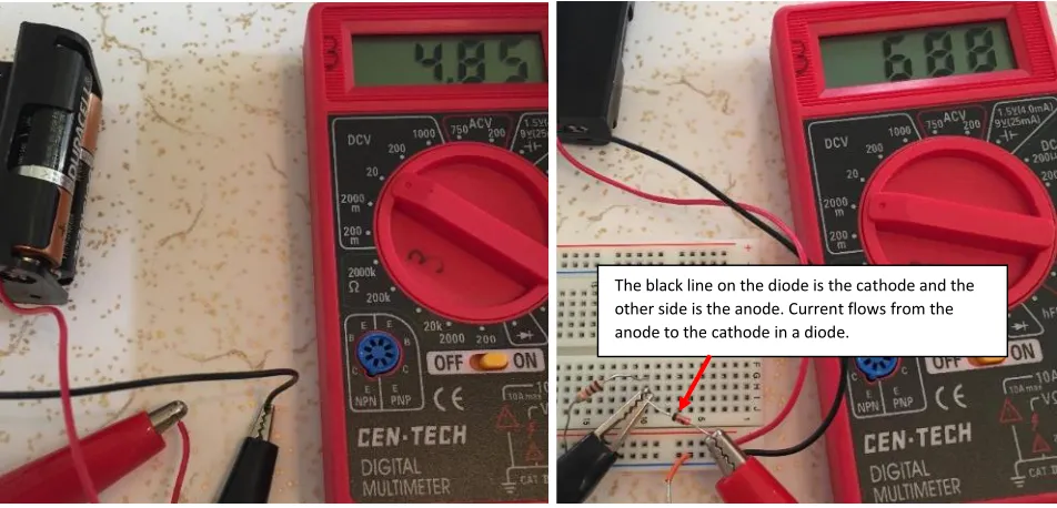
When measuring voltage across a battery with a Multimeter (as shown in the left side of Figure 1.5) the + probe (Red) goes on the positive side of the battery and the – probe (black) goes on the negative side. If the probes are put on the wrong side (red on - & black on +) then a negative voltage will be displayed. Like the resistance reading measurement discussed earlier, the Multimeter setting must be set correctly. For DC Voltage reading it is set to DCV at a value that is higher than the voltage it reads. For best
12
to read the 4.85 V battery pack (that includes 3 AA batteries) instead of 200 V. If the 2,000 mV (i.e. 2 V) setting was erroneously used instead of 20 V, a vertical line would be displayed on the screen of the meter to prompt you to increase the voltage setting. When measuring the voltage across a component such as a 1N914 silicon diode that has an approximate voltage drop of 0.7 V when forward biased (as shown in the right side of Figure 1.5) the meter will read a positive value if the + meter probe is placed on the side of the component with a larger voltage. Another way of looking at the sign of the voltage read by the meter is that a positive voltage on the meter display means that current is flowing through the component in the direction from the + (Red) probe to the – (Black) probe. This should make sense because current always flows from a higher voltage to a lower voltage across electrical components (this doesn’t include sources). It must be noted that voltage sources or current sources (discussed later) usually source current so the current inside the power source often flows from a lower voltage to a higher voltage.
[image:13.612.73.549.268.497.2]
Figure 1.5: Multimeter voltage measurements of a battery pack (left) and 1N914 Diode (right) Example 1.7) if you read a voltage with a Multimeter that has a value of 125 mV what meter setting
should be used?
Answer: You would use a DCV setting that is greater than 125 mV. The most accurate setting would be the 200 m setting.
There are also other components that act similarly to voltage sources when placed in a circuit. A diode, like the one shown in Figure 1.5, that is “forward biased” is one such example. A diode acts like a current valve, where current can only flow in one direction. If the diode is placed such that current can flow through it then it will be forward biased and will act similarly to a battery (if the constant drop model of the diode is used) with a voltage value that depends on the type of diode. If the diode is put in the “wrong” direction into the circuit, then it will be in “reverse bias” and act as an open circuit (resulting in no current flow). A silicon based diode like those used in rectifier or switching circuits is often assumed to have a diode drop of 0.7 V. Light Emitting Diodes (LED) typically have much larger voltage drops when
13
they are forward biased. The actual voltage drop across any diode will increase exponentially as more current flows through it (and for LEDs the brightness will also increase with more current), but using the constant drop model and modeling the diode as a constant voltage value allows for simplified
calculations. The forward bias voltage-drop for the LEDs used in this class will typically range from 1.5 to 2.5 volts. Unless otherwise stated we will assume red LEDs have a constant 1.8 V drop and green LEDs have a 2 V drop when they are forward biased. Figure 1.6 shows a green LED that is put in the correct direction in the circuit so that it is forward biased and lights up (left) and the constant drop circuit model where the LED is replaced with a 2 V battery (right).
Figure 1.6: Example of a circuit with an LED in forward bias (left) and constant drop model (right).
Since a 1 kΩ resistor was used in the circuit in Figure 1.6 the 2V constant drop model value closely matched the actual LED voltage of 2.05 V. If a much smaller resistor would have been used the LED voltage would have been much higher and if a much larger resistor would have been used the LED voltage would have been much lower. For example, according to Multisim (which produces a fairly
accurate model of a green LED) if the 1 kΩ resistor is replaced with a 100 Ω resistor the LED voltage increases to 2.23 V and if the resistor is increase to 10 kΩ the LED voltage decreases to 1.87 V. Keep this inaccuracy in mind when working with LEDs on the project.
14
1.1.3c - Current
One of the biggest issues students have when trying to learn circuits is getting
current and voltage confused.
Before discussing current let’s look at some statements about voltage. Figure 1.7 provides some visual explanations to these statements.
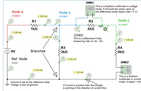
• The Voltage at ground is always assumed to be zero.
• Voltage is the same at all points on a node (a place shared by 2 or more circuit elements). For example, the blue line that represents Node b in Figure 1.7 is 6 V at every point on the blue line.
• Voltage can be measured either 1) across components (see XMM1) or 2) at a Node (See Va, Vb, Vc) with respect to ground (0 Volts).
[image:15.612.62.555.373.693.2]• When measuring voltage across one or more components with a Multisim Multimeter (see XMM1) you wire two different nodes to the + and – terminals and then double click on the meter and put it in Volts mode (V) and DC mode (straight line). XMM1 reads the voltage value across R2, which is also the value of Vab. Vab is the difference between node voltages Va and Vb. Vab is an example of double subscript notation (Vab = Va – Vb). Va is an example of single subscript notation. Va is the voltage at node a, and the reference is ground. When ground is not the reference for the measurement differential probes can be used to measure the voltage difference between nodes.
15
The following statements about current are contrasted to voltage.
• Current flows through circuit elements. You have a voltage drop across elements.
• Components (this doesn’t include sources) DON’T change the value of the current, but DO change the value of the voltage.
• Current doesn’t change as it runs through components until it is split in a branch (see Figure 1.7). Voltage doesn’t change at a branch unless it goes through a circuit element.
• Double subscript notation (e.g. VAB) is not used for current since the current doesn’t change
through components.
• When measuring current with a Multisim Multimeter (see XMM2 in Figure 1.7), you have to break the circuit and run it through the meter and then double click on the meter and put it in Amps mode (A) and DC mode (straight line). The same process is used to measure the current with an actual Multimeter as shown in Figure 1.8.
CAUTION: If you place the meter probes across a resistor (i.e. one probe on each side) and put the meter in current mode you will likely blow the fuse and/or damage the meter because the resistor that limits the current in the circuit is bypassed, which might result in excessive current flowing through the meter. Students frequently make this mistake when measuring current instead of “breaking” the circuit to measure the current, as shown in Figure 1.8. If you blow the fuse, the current will measure zero for all current settings, but the voltage readings will still work. Getting the fuse replace is not ideal, but it is a simple thing to fix. However, the Multimeter might also have its internal circuitry damaged, so test the current readings at another setting to see if you are getting wrong results at the setting you were using when you measured current incorrectly. Measurement mistakes from students in ENGR 2431 have caused a lot of blown fuses and a lot of damaged meters (especially the 20 mA setting), so make sure you measure current correctly and make sure it is in the correct mode when you turn it on.
Note: In Figure 1.7 all of the Multisim probes only have I and V, but when the current and voltage probes are normally placed in Multisim the “Instantaneous and periodic” probe setting is the default so you will see 5 voltage measurements (as shown in Figure 1.7a). From top to bottom these voltage measurements are: 1-Instantaneous, 2-peak to peak (Vpp), 3-Root-Mean-Square (Vrms), 4-average (Vavg), and the 5-frequency. The average voltage is labeled V(dc) in the Multisim probe because Vavg is equivalent to the DC value. The instantaneous voltage is the value at a specific time and will
continuously change as the AC current flows through the circuit. These four additional parameters for voltage or current are only used for AC circuits. When dealing with DC circuits there is only one type of voltage and current so only the instantaneous measurements are needed. To get only the DC current or voltage, click on the probe settings and change the default to “Instantaneous Only” (see Figure 1.7a).
16
[image:17.612.71.552.121.355.2]The circuit in Figure 1.8 shows a simple circuit with two resistors in series with a battery pack that has three AA batteries in it. You can see how one end of one of the resistors is pulled out of the breadboard to break the circuit and allow current to be measured with the Multimeter.
Figure 1.8: Circuit showing current measured with a Multimeter.
Another trick that will help you understand current better is to define Ohm’s Law differently for the current flowing through a resistor as shown in equation 1.6. This equation yields a positive current flowing in the direction from Node A to Node B if Va is greater than Vb. Va and Vb simply refer to the voltage at Node A and B, respectively. This is called single subscript notation. However, Equation 1.6 could also be written in double subscript notation by replacing Va – Vb with VAB.
[1.6]
I
𝑅𝑅=
ΔVR=
𝑉𝑉𝑎𝑎−𝑉𝑉𝑏𝑏R
CAUTION: When determining current through a resistor ALWAYS find ΔV. An extremely common mistake is for people to calculate current through a resistor using I = V/R instead of I = ΔV/R.
Example 1.8) using equation 1.6 solve for the current flowing through the R1 resistor in Figure 1.8. Answer: Applying equation 1.6 to the circuit in Figure 1.8 yields:
I
𝑅𝑅1=
Δ
R =
V
𝑉𝑉
𝑎𝑎− 𝑉𝑉
R
𝑏𝑏=
4.84
1000
𝑉𝑉
−
2.42
Ω
𝑉𝑉
=
𝟐𝟐
.
𝟒𝟒𝟐𝟐
𝒎𝒎𝒎𝒎
The reason that solving for the current using equation 1.6 is a good idea is that it helps you avoid careless mistakes like calculating IR1to be 9V/1000Ω (This is wrong because it only includes the voltage
on one side of the resistor). Making this type of mistake is very common for students learning circuits for the first time, as highlighted in the CAUTION above.
R
17
In addition to voltage sources, there are also circuit elements called current sources. There are
dependent and independent current sources and (just like voltage sources) there are also ideal and non-ideal current sources. A non-non-ideal current source has a parallel resistor (with a large value) across it, but an ideal current source assumes that the parallel resistance across it is infinity, which results in the resistor in parallel with it having no affect. In this course, we will only learn about the ideal, independent current sources. The circuit symbol is shown in the far right frame in Figure 1.9.
To find an independent DC current source in Multisim go to the Signal_Current_Sources Family under the Sources Group and select the DC_Current Component as shown in Figure 1.9. Current sources have a non-zero voltage across them much like voltage sources have current that flows through them.
Figure 1.9: Ideal Independent Course Source Location in Multisim
Example 1.9) If a 55 mA current source is connected to a 100 Ω resistor, what is the voltage across the current source?Answer: Using Ohm’s Law, Vs = I * R = 55 mA * 100 Ω = 5.5 V
The ideal current source will cause the current in the section of the circuit it is connected to be fixed to the value of the current source (as shown in the example 1.10). Unlike voltage sources that can easily be understood by thinking of it as a battery, a current source is not as easy to visualize. Current sources are created from multiple transistors and are often used in Integrated Circuits (ICs), which are important topics in electronics. The following link provides a good description of the design and uses of current sources.
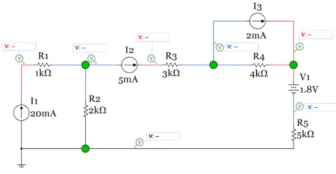
http://www.allaboutcircuits.com/technical-articles/the-basic-mosfet-constant-current-source/ Example 1.10) Answer the following questions about the circuit in Figure 1.10.
Using only Ohm’s Law which resistors can you determine the voltage across?The resistors connected directly to the current sources have the value of the current source flowing through them so the voltage can be determined with only Ohm’s law (V = IR). These resistors are R1 and R3.
VR1 = 20 mA * 1kΩ = 20 V and VR3 = 5 mA * 3 kΩ = 15 V.
More complicated methods are needed to solve for the other voltages in the circuit.
How many nodes are in this circuit?A voltage probe is put on each unique node. There are 7 nodes. One
of these 7 nodes is called the reference node.
How many branches are in this circuit?The branches are marked with green circles. There are 4 branches.
18
Figure 1.10: Circuit for Example 1.10
Example 1.11) Using the circuit in Figure 1.10 with the Voltage probe values given (shown in Figure 1.11) determine the values of IR2, IR4, and IR5 using equation 1.6.
Figure 1.11: Circuit for Example 1.11
[image:19.612.72.553.396.641.2]19
Section 1.1.4 – Power and Energy
DC Power has units of Watts (or W) and has three different equations that can be used (1.7, 1.8, and 1.9). Power can either be supplied or dissipated. Supplied power is also called delivered power.
Dissipated power is also called absorbed power. Supplied power is denoted with a negative sign, but the sign is often ignored and just the magnitude of the power supplied is determined. In this course only the magnitude of the power will be required (in other words, don’t worry about the sign of power and just list all power as positive). The reasoning for this is demonstrated in the following paragraph.
If you are asked “What is the power supplied by I1 in Figure 1.11?” it is implying you are only wanting the magnitude (which is equal to P = 0.02 ∙ 50 = 0.1 W) since it states the power is “supplied” in the question. The actual power would have a negative sign, but the power that is supplied can be listed as a positive value. If the question said “What is the power of I1?” then you would include a negative sign (- 0.1 W) to show that it is supplied power.
[1.7]
𝑃𝑃
= V
∙
I
[1.8]
P =
VR2[1.9]
P = I
2∙ 𝑅𝑅
Note: When determining the power of a voltage or current source ONLY use equation 1.7. When finding the power dissipated by a resistor it is easier to use either equation 1.8 or 1.9.
The conservation of electric power theorem is very important in circuits and is shown in equation 1.10.
[1.10]
∑ 𝑃𝑃
𝑠𝑠𝑠𝑠𝑠𝑠𝑠𝑠𝑠𝑠𝑚𝑚𝑠𝑠𝑠𝑠=
∑ 𝑃𝑃
𝑠𝑠𝑚𝑚𝑠𝑠𝑠𝑠𝑚𝑚𝑠𝑠𝑎𝑎𝑡𝑡𝑠𝑠𝑠𝑠or if you prefer
∑ 𝑃𝑃
𝑠𝑠𝑠𝑠𝑠𝑠𝑚𝑚𝑑𝑑𝑠𝑠𝑑𝑑𝑠𝑠𝑠𝑠=
∑ 𝑃𝑃
𝑎𝑎𝑏𝑏𝑠𝑠𝑎𝑎𝑑𝑑𝑏𝑏𝑠𝑠𝑠𝑠 By performing a power balance using equation 1.10 in a circuit you can check your voltage and current answers to see if any calculation errors were made. Resistors and diodes always dissipate power and will go on the right side of equation 1.10. Voltage and current sources depend on the polarity in which they are placed in the circuit to determine whether they are suppliers or dissipaters.• A voltage source is a dissipater only of it is placed so that the current flowing through it goes from the + side to the – side.
20
to be damaged unless it is a rechargeable battery and you are connecting it to a larger voltage source for recharging purposes.
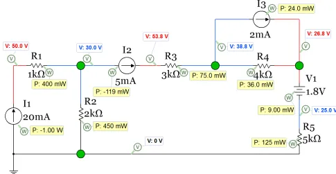
[image:21.612.69.554.165.416.2]Example 1.12) Using equation 1.10 perform a power balance for the circuit in Figure 1.12. This is the same circuit as shown in Figure 1.10 and Figure 1.11, but now Multisim power probes are included so you can check the answers obtained from hand calculations.
Figure 1.12: Circuit for Example 1.12
Answer: The dissipating elements are: R1, R2, R3, R4, R5, V1, and I3.
Find the voltage or current of each dissipating element so the total power dissipated can be calculated. V1 explanation - Since it is placed so that the current flowing through it goes from the + side to the – side it is a dissipater. This is verified in Multisim since the power probe has a positive value.
I3 explanation - Since it is placed so that the voltage across it has a positive value in the direction of the current flow it is a dissipater. This is verified in Multisim since the power probe has a positive value. From example 1.11, IR2 = 15 mA, IR4 = 3 mA, IR5 = 5 mA.
Using the knowledge of how current sources work: IR1 = I1 = 20 mA, IR3 = I2 = 5 mA, IV1 = IR5 = 5 mA. The magnitude of the voltage across I3 is 38.8 – 26.8 = 12 V. The sign of this voltage is not needed since we have determined it is a dissipater it will have a positive power written on the right side of equation 1.10.
• PR1 = IR12 ∙ R1 = (0.02)2∙ 1000 = 0.4 W
• PR2 = IR22 ∙ R2 = (0.015)2∙ 2000 = 0.45 W
21
• PR4 = IR42 ∙ R4 = (0.003)2∙ 4000 = 0.036 W
• PR5 = IR52 ∙ R5 = (0.005)2∙ 5000 = 0.125 W
• PR2 = IR22 ∙ R2 = (0.015)2∙ 2000 = 0.45 W
• PV1 = IV1 ∙ V1 = (0.005) ∙ 1.8 = 0.009 W
• PI3 = II3 ∙ VI3 = (0.002) ∙ 12 = 0.024 W
∑ Pdissipated =0.4 W + 0.45 W + 0.075 W + 0.036 W + 0.125 W + 0.45 W + 0.009 W + 0.024 W = 1.119 W The supplying elements are I1 and I2 since they are placed so that the voltage across them have
negative values in the direction of the current flow. This is verified in Multisim since the power probe have negative values for PI1 and PI2. The circuit from the previous page is copied below.
Find the voltage across I1 and I2 so power can be calculated. VI1 =50 – 0 = 50 V, VI2 =53.8 – 30 = 23.8 V
• PI1 = I1 ∙ VI1 = (0.02) ∙ 50 = 1.0 W
• PI2 = II2 ∙ VI2 = (0.005) ∙ 23.8 = 0.119 W
∑ Psupplied = 1.0 W + 0.119 W = 1.119 W
Equation 1.10 is satisfied since ∑ Pdissipated = ∑ Psupplied = 1.119 W
22
number of mAh the battery uses. When the number of mAh reaches a level close to the rating the battery will become depleted and need to be replaced (or recharged if using a rechargeable battery). You will also see ratings on equipment. The equipment will typically be made to work with a set voltage and then the power or current rating is often provided. For example, a device that operates from a four AA batteries might state in the technical specifications that it “draws” 50 mA. The power rating for that device would be equal to the nominal voltage (4 * 1.5 = 6 V) multiplied by the current it draws (0.05 A), which is 0.3 Watts. Alternatively, the technical specifications might give a power rating instead of a current draw. If the power rating was given as 0.3 Watts then you would expect it to draw 50 mA of current when plugged into a 6 V battery pack. Once you know the current that the piece of equipment or circuit draws then you can figure out how long different types of batteries would last if connected to the equipment or circuit. If no power rating or current draw information is given in the specification sheet for the piece of equipment, then you can measure the current with a Multimeter to determine how much current it draws to help you determine how long the battery will last.
Example 1.13a) if you are using a toy RC car that runs on 6 AAA batteries and it draws approximately 70 mA when operating, how long will the batteries last if Alkaline batteries are used? This example assumes that the RC car will operate at very low voltages as the battery voltage reduces over time. Also, what is
the power rating of the RC car?
AAA Alkaline batteries have a 1.5 V nominal voltage so the voltage source for the RC car is 6 * 1.5 = 9V. The power rating would be equal to 70 mA * 9 V = 0.63 Watts. Since each of the 6 batteries are
operating in series, each of them will all have approximately 70 mA flowing through them. So the number of hours they will last will equal the mAh rating of a AAA alkaline battery divided by 70 mA. For an Energizer E92 Alkaline battery the data sheet shows the mAh rating is approximately 1000 mAh. So if this type of alkaline battery is used the RC toy car would completely run down the batteries to a very low value after approximately 1000/70 = 14.3 Hrs. This is not an exact value because it is not certain at what voltage level the RC car would stop working. Additionally, an RC car will draw different amounts of current at different speeds and when operated on different types of terrains so 70 mA is likely not a very accurate estimate. Additionally, each of the AAA batteries would drop in voltage over time and the car’s motors will not operate at voltages near zero so it is likely that the car would stop working much sooner than 14.3 Hrs.
For AC circuits a circuit breaker is a common way to limit the amount of current in a circuit. Another method to protect an AC circuit is by using fuses. A common example of an AC fuse application is strings of Christmas lights, where a fuse is often embedded into a compartment next to the connector. For DC circuits fuses are much more common than circuit breakers. The fuses in your automobile that control the current supplied to different circuits by the 12 V car battery is a great example of a DC fuse application. The fuse is made by having a thin metallic conductor that will break at a specified current level. Once the fuse breaks (due to the excessive heat that occurs at its rated current) it becomes an open circuit and current is shut off to the circuit. Once the fuse is “blown” (i.e. the piece of metal breaks) it must be replaced. If the fuse continues to blow it is an indication that there is a problem with the circuit.
23
[1.11]
𝐸𝐸
= P
∙
t
• If units of Watts is used for power and seconds for time then the units for energy is Joules. • If units of kilowatts (kW) is used for power and hours (hrs) for the units of time, then the units
for energy is kilowatt hours (kWhrs). This is the unit for energy that is used to determine how much you pay for your home electricity bill.
Example 1.13b) if you have a portable TV that plugs into a 9V DC outlet in your car and the TV draws a constant 400 mA while operating, calculate the power rating of the TV and the amount of energy (in kWhrs and Joules) converted over a 3.5-hour time period.
Power Rating = 9 V * 0.4 A = 3.6 W
Energy (Joules) = Pwatts ∙ timeseconds = 3.6 W∙ (3.5 hrs * 3600 seconds/hr) = 45,360 Joules Energy (kWhr) = PKW ∙ timehrs = 0.0036 kW ∙ (3.5 hrs) = 0.0126 kWhr
Section 1.2 – Combining Resistors in Parallel or Series
Combining elements that are in series or parallel is a skill that will be used at numerous times in this course.
• In this section of module 1 you will combine all of the resistors in a circuit so that you are left with only one source and one resistor.
• In Module 2 (section 2.6) you will use this skill to determine the Thevenin equivalent resistance.
• In Module 3 (section 3.6) you will use the same process to combine inductor networks and capacitor networks.
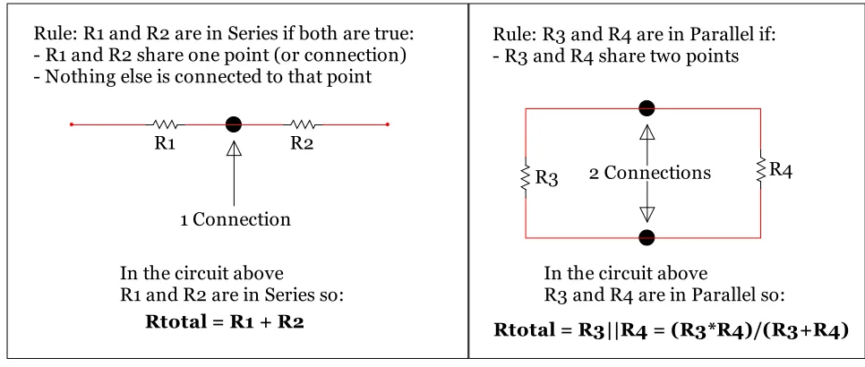
[image:24.612.69.552.482.687.2]To correctly combine resistors, the definitions of series and parallel needs to be crystal clear. Figure 1.13 shows the definitions.
Figure 1.13: Series and Parallel Definitions
R1 R2
R3 R4
Rule: R3 and R4 are in Parallel if: - R3 and R4 share two points Rule: R1 and R2 are in Series if both are true:
- R1 and R2 share one point (or connection) - Nothing else is connected to that point
Rtotal = R1 + R2 In the circuit above
R1 and R2 are in Series so: In the circuit aboveR3 and R4 are in Parallel so:
Rtotal = R3||R4 = (R3*R4)/(R3+R4) 1 Connection
24
The equation for multiple resistors in series is:
[1.12]
𝑅𝑅
𝑇𝑇𝑎𝑎𝑡𝑡𝑎𝑎𝑠𝑠=
𝑅𝑅
1+
𝑅𝑅
2+
𝑅𝑅
3+
∙∙∙ 𝑅𝑅
𝑁𝑁The equation for 2 resistors in parallel is:
[1.13]
𝑅𝑅
𝑇𝑇𝑎𝑎𝑡𝑡𝑎𝑎𝑠𝑠=
((𝑅𝑅𝑅𝑅11+∙𝑅𝑅𝑅𝑅22))Note: This equation ONLY works for 2 resistors. The equation for combining 3 or more resistors in parallel is:
[1.14]
𝑅𝑅
𝑇𝑇𝑎𝑎𝑡𝑡𝑎𝑎𝑠𝑠=
1 1𝑅𝑅1 +𝑅𝑅21 +𝑅𝑅31 +∙∙∙𝑅𝑅𝑁𝑁1
Note: You can also combine multiple parallel resistors 2 at a time using equation 1.13 instead of using equation 1.14 and combining them all at once. Since equation 1.14 has “fractions of fractions” students frequently make calculation mistakes when entering this into their calculator so it is a good idea to avoid using the equation if possible.
Another option for multiple resistors in parallel is to find the total conductance first and then find the total resistance in a two-step process as shown below.
Step 1) GTotal = G1 + G2 + G3 + ∙∙∙ GN or GTotal = 1/R1 + 1/R2 + 1/R3 + … 1/RN
Step 2) Rtotal = 1/GTotal
Guidelines for Reducing Circuits by Combining Elements that are in Series or Parallel:
1) It is only a good idea to find the total resistance in a circuit if there is ONLY one source or can be reduced to a circuit with 1 source (either 1 current source or 1 voltage source). For example, if you have 4 AAA batteries in series you can combine all 4 of the 1.5 V batteries to make a 6 V battery.
2) If you are trying to solve for a specific resistor voltage or current, it is likely a bad idea to combine that resistor with another resistor because it might take away the ability to find that specific resistor’s voltage or current.
3) When combining resistors start with the 2 resistors as far away from the source as possible and work towards the source.
4) Remember that you can move resistors anywhere along a wire as long as you don’t move it across a branch. By dragging resistors around it is often much easier to see whether it is parallel or in series with another resistor (or if 2 resistors are neither in parallel or series and can’t be combined).
5) When combining resistors, you will make fewer mistakes if you redraw the circuit each time you combine two resistors. I know it takes longer, but if you are prone to making mistakes redrawing the circuit each time a resistor combination is made can really help.
6) Always perform a sanity check when you are done combining resistors. Some tricks for catching mistakes are as follows:
o If adding resistors in series the total resistance will be larger than the largest resistor.
o If adding resistors in parallel the total resistance will be smaller than the smallest resistor.
o If adding 2 resistors in parallel that are close to the same value, the result will be fairly close to half of the average of the 2 resistors. If these 2 resistors are identical then the result will
25
All 6 of these guidelines are referenced in example 1.14. Even though example 1.14 is fairly simply it is a really good idea to go through it so you can see how these 6 guidelines are applied to a problem and you can apply them to more complicated resistor combination problems.
Example 1.14) Find the total resistance and the power supplied by the battery in the following circuit.
Figure 1.14: Circuit for Example 1.14
• Question 1) Can we even find the total resistance in this circuit?
Yes, Guideline 1 states that if there is one source then you CAN find the total resistance in a circuit. • Question 2) Does finding the total resistance help us find what is asked for in the problem?
Yes, when asked for the source current of a battery or the voltage across a current source finding the total resistance is usually a great idea. In this problem we are not asked to find the resistor current or voltage of any of the resistors we are combining so we are not violating Guideline 2 when combining resistors.
• Question 3) Which 2 resistors should be combined first?
Guideline 3 states to start as far away from the source as possible so that says to start with R2 and R3. A common mistake is for students to forget this guideline and try to combine R1 and R2 (thinking they are in series). R1 and R2 do share a point which is the first rule for series, but they do not obey the second rule (“nothing else is connected to that point”) because R3 is also connected to that point. In this case R1 and R2 are not in series or parallel and can’t be combined.
• Question 4) Now that we know to combine R2 and R3, how do we determine if they are in series or parallel?
It is often hard to visualize that resistors are in parallel unless they are parallel with each other like shown in Figure 1.13. Guideline 4 states that you can drag resistors along a wire. If this were done with R3 the following circuit would be produced. Now, it is easy to see that R2 and R3 are in parallel.
And also see that Rx = R2||R3 = (4k ∙ 6k)/( 4k + 6k) = 2.4 kΩ
R1
1kΩ
R3
6kΩ
Vs
12V
R2
4kΩ
R1 1kΩ
R3 6kΩ Vs
12V R24kΩ
26
The Guideline 6 sanity check states 2 resistors in parallel should give a result that is less than the
smallest resistor (2.4 kΩ is less than 4 kΩ) and if they are close to each other the result should be close
to half the average (4k and 6k aren’t “that close” to each other, but half the average is equal to 2.5 kΩ which is not that far off from 2.4 kΩ).
At this point it is pretty easy to see how to combine Rx with R1, but Guideline 5 states that the circuit should be redrawn to avoid making mistakes. The following circuit is what remains.
Now it is easy to see that R1 and Rx are in series because they share a point AND nothing else is connected to that shared point.
• Rtot = R1 + Rx = 1 kΩ + 2.4 kΩ = 3.4 kΩ
The source current can now be found from Ohm’s Law and the power found from equation 1.7. • Is = Vs/Rtot = 12/3.4 kΩ = 3.53 mA
• PSupplied = Is * Vs = 3.53 mA * 12 V = 42.36 mW
Once you get more comfortable with these types of problems you can write an equation for the total resistance (like shown below) in the circuit from the original circuit, but until your skill is increased it is best to methodically go through the process like was done in this example.
• Rtot = R1 + R2||R3 = 1 kΩ + (4k ∙ 6k)/(4k + 6k) = 3.4 kΩ
If you want to use Multisim to verify the total resistance in a circuit you must remove the source and replace it with a Multimeter in Ohms mode as shown below.
Note: It doesn’t matter which side connect the Multimeter + and – pins are connected to when
measuring resistance because it always is a positive value. In other words, polarity doesn’t matter with resistance.
R1 1kΩ
Vs 12V
27
Example 1.15) Fine the total resistance and the power supplied by the current source in the following circuit.
Figure 1.15: Circuit for Example 1.15
By inspection: Rtot = R1|| {R2 + R3 + [R4|| (R5+R6)]} = 10|| {5 + 15 + [50|| (50)]} = 10||45 = 8.182 Ω Multisim verification:
Step by Step solution to finding Rtotal.
- Step 1) Start as far away from as possible from the source. R5 & R6 are in series so Ra = 20 + 30 = 50 Ω - Step 2) Next, R4 & Ra are in series. Rb = R4||Ra = 50||50 = 25 Ω
- Step 3) Next, R2, R3, and Rb are in series. Rc = R2 + R3 + Rb = 5 + 15 + 25 = 45 Ω - Step 4) Finally, R1 & Rc are in parallel. Rtot = R1||Rc = 10||45 = 8.182 Ω
Step by Step solution to finding the power supplied.
- Step 1) the voltage across the current source is Vs = I1 * Rtot = 2.5 A * 8.182 Ω = 20.5 V
- Step 2) from equation 1.7) Psupplied = I1 * Vs = 2.5 A * 20.5 V = 51.1 W (This is the power magnitude)
R1
10Ω
R3
15Ω
I1
2.5A
R2
5Ω
R4
50Ω
R5
20Ω
R6
28
Example 1.16) Answer the following questions for the circuit below.
Figure 1.16: Circuit for Example 1.16 What is the total resistance in the circuit? 𝑅𝑅𝑇𝑇= [(R4 + R5) || R3 || R2] + R1
What is the current supplied by the battery?
Determine the voltage drop across R1 using only the previous calculation and Ohm’s Law. VR1 = IS * R1 = 3.99 mA * 3000Ω = 11.97 V
Determine the current through R2 and R3 using only the previous calculation and Ohm’s Law. If the voltage drop across R1 is 11.97 V that means the voltage at the node on the top side of both R2 and R3 is equal to 15 – 11.97 = 3.03 V. The voltage on the bottom side of both R2 and R3 is 0V since it is connected to the reference node (ground). Using the equation 1.6 version of Ohm’ Law these currents can be calculated as:
• IR2 = (3.03 V – 0 V)/4kΩ = 0.7575 mA
• IR3 = (3.03 V – 0 V)/1kΩ = 3.03 mA
“Reduce and Return” Method and a Discussion of what is to come
Finding the current through R2 and R3 in the previous example was found by reducing the circuit to one resistor and then inserting (or returning) the source current that was found back into the original circuit to determine new voltages and currents. This method is fairly easy to solve for R2 and R3 voltages and currents, but to determine the R4 or R5 current or voltages new methods that have not been covered yet in this document are needed. There are two options available in Module 1.
1) A KVL loop equation (see example 1.18 in section 1.3) could be written around the outside loop to solve for the current through R4 and R5 and then Ohm’s Law could be used to get VR4 and VR5.
29
These are the only two Module 1 methods that could be used to solve for IR4, but Module 2 will show
how matrices can be used to solve this circuit for IR4 in one step instead going through multiple Module 1
calculation steps. Reducing the circuit down to one resistor and then rebuilding the circuit and using basic Module 1 techniques to find other resistor voltages and currents in the circuit is sometimes referred to as the “Reduce and Return” circuits technique. This cumbersome technique is easy to mess up and is personally considered an inferior method to using the matrix methods described in Module 2. This is especially true when multiple calculation steps are required. For instance, the section 1.2 method of combining resistors is likely the easiest method to solve for IS. Additionally, doing basic reduce and
return techniques using Ohm’s law equations 1.4 and 1.6 to find R2 and R3 currents and voltages is not too difficult. However, once you are asked to go to a third step in the Reduce and Return methodology where a KVL or KCL is required to solve for R4 and R5 currents and voltages the Reduce and Return method is no longer a good idea and should be scrapped for Module 2 methods.
Section 1.3 – Kirchhoff’s Voltage Law (KVL) and Voltage Divider Rule (VDR)
Kirchhoff’s Voltage Law (KVL) is defined as:
[1.15]
∑ 𝑉𝑉
𝑑𝑑𝑚𝑚𝑠𝑠𝑠𝑠𝑠𝑠=
∑ 𝑉𝑉
𝑠𝑠𝑑𝑑𝑎𝑎𝑠𝑠𝑠𝑠or
∑ 𝑉𝑉
𝑎𝑎𝑑𝑑𝑎𝑎𝑠𝑠𝑚𝑚𝑠𝑠𝑎𝑎𝑠𝑠𝑠𝑠𝑎𝑎𝑠𝑠𝑠𝑠𝑠𝑠𝑠𝑠𝑎𝑎𝑎𝑎𝑠𝑠= 0
The preferred version for KVL (equation 1.15) is the sum of voltages around a closed loop is equal to zero because it is sometimes difficult to know whether a voltage source causes a voltage drop or rise in a circuit. The term “around a closed loop” means that you travel around the circuit and start and stop at the same location. The sum of the voltages across the elements that you travel through (any path you choose) will be equal to zero if the starting and ending points are the same.
When performing a KVL the following steps are followed:
1) Write the polarity (+ and – signs) across every element in the circuit.
a. For voltage sources the polarity is set by the battery symbol (+ sign on the long end line) b. For current sources the head side of the arrow has the + sign.
c. For resistors the + and – signs are written in the direction of the assumed current flow. 2) Start at a point in the circuit and travel around any path you choose until you get back to the
same starting point. As you are travelling around the path you write down the voltage of the elements (I*R for resistors and Vs for sources) you go across using the sign that you travel through. If you travel into the + sign the voltage term is positive and if you travel into the – sign the voltage term is negative.
30
Example 1.17) Write the KVL equation for the circuit below and solve for the current in the loop and the voltage across R4. Note: The Multisim current and voltage combo probe is only added to this circuit to show the calculations agree with Multisim. You cannot use Multisim probe values in your calculations unless it is specifically stated to do so in the problem statement.
Figure 1.17: Circuit for Example 1.17
Step 1) the direction of the current is assumed and the polarity across every element is written (+ & - signs)
Step 2) KVL Equation: – 12 + 5 * IS + 10 * IS + 20 * IS + 25 * IS = 0
Step 3) IS is the only unknown so it can be solved for as: IS = 12/(5 + 10 + 20 + 25) = 0.2 A
• Since the current is calculated to be a positive value the direction assumed in step 1 was correct. Step 4) the voltage across R4 can now be found by Ohm’s Law. VR4 = Is * R4 = 0.2 * 25 = 5 V
A shortcut called the Voltage Divider Rule (VDR) can be used in problems like example 1.17 If and only if you have a circuit loop that has the same current flowing through all of the elements (i.e. all elements are in series) and only one voltage source is in the loop
[1.16]
𝑉𝑉
𝑥𝑥=
𝑉𝑉𝑅𝑅𝑠𝑠𝑡𝑡𝑡𝑡𝑡𝑡𝑎𝑎𝑡𝑡∙𝑅𝑅𝑥𝑥Since the previous example obeys the rules that allow VDR to be used (all elements are in series and there is only one voltage source) then VR4 can be solved more efficiently by using equation 1.16.
𝑉𝑉
𝑅𝑅4=
𝑉𝑉
𝑅𝑅
𝑠𝑠∙
𝑅𝑅
4 𝑡𝑡𝑎𝑎𝑡𝑡𝑎𝑎𝑠𝑠=
12
∙
25
5 + 10 + 20 + 25 =
𝟓𝟓
𝑽𝑽
So if the only thing you are asked to solve for is the voltage across one of the resistors in a circuit that has all elements in series and only one voltage source then VDR is a good idea because it turns a 4 step problem into a 1 step problem. However, VDR is probably the most incorrectly used formula in all of circuit analysis so make sure that it is only used if the circuit has all elements in series and only one voltage source.
Example 1.18) In example 1.16 in section 1.2 the Reduce and Return Method utilizing a KVL to solve for the current through R4 and R5 was mentioned. In this example it will be completed by writing each of the KVL equations that allow the current through R4 and R5 to be solved. Assume you already know the values calculated in example 1.16 (i.e. IR1= 3.99 mA →, IR2 = 0.7575 mA ↓, IR3 = 3.03 mA ↓).
Rx is the resistor you are finding the voltage across (Vx). Vs is the one
and only voltage source in the circuit and Rtotal is the total resistance
31
Figure 1.18: Circuit for Example 1.18
Option 1) KVL around the outside loop (see polarity below)
KVL: - 15 + IS ∙ R1 + Ix ∙ R4 + Ix ∙ R5 = 0 - 15 + 3.93 mA ∙ 3 kΩ + Ix ∙ 10 kΩ + Ix ∙ 5 kΩ = 0 Ix = (15V -11.97)/(10 kΩ + 5 kΩ) = 0.202 mA
Option 2) KVL from around the two rightmost loops including R2, R4, and R5 (see polarity below)
KVL: - IR2 ∙ R2 + Ix ∙ R4 + Ix ∙ R5 = 0 - 0.7575 mA ∙ 4 kΩ + Ix ∙ 10 kΩ + Ix ∙ 5 kΩ = 0 Ix = (0.7575 mA ∙ 4 kΩ)/(10 kΩ + 5 kΩ) = 0.202 mA
Option 3) KVL around only the rightmost loop including R3, R4, and R5 (see polarity below) +
+
+
-
- -
- +
Ix
+
+
-
-
- +
32
KVL: - IR3 ∙ R3 + Ix ∙ R4 + Ix ∙ R5 = 0 - 3.03 mA ∙ 1 kΩ + Ix ∙ 10 kΩ + Ix ∙ 5 kΩ = 0 Ix = (3.03 mA ∙ 1 kΩ)/(10 kΩ + 5 kΩ) = 0.202 mA
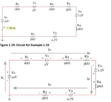
[image:33.612.74.443.250.589.2]Example 1.19) In this example multiple voltage sources are included. Find the current in the circuit.
Figure 1.19: Circuit for Example 1.19
Step 1) the direction of the current is assumed and the polarity across every element is written. Step 2) KVL Equation: – 12 + 1k * IS + 2 + 2k * IS + 3k * IS – 1.5 + 4k * IS + 0.7 + 5k * IS = 0
Step 3) IS is the only unknown so it can be solved for as: IS = (12+1.5-2-.7)/(1k+2k+3k+4k+5k) = 0.72 mA
• Since the current is calculated to be a positive value the direction assumed in step 1 was correct. The trickiest part about this problem is getting all of the signs correct. If you carefully follow the KVL rules described earlier when labeling each element’s polarity, then you will have no problem. V1 is a realistic value and in a realistic polarity because it could be the constant drop model of a green LED. V3 is also a realistic value and polarity because it could be the constant drop model from a silicon based
+ +
-
-
- +
33
switching diode. It is important to note that V2 is not placed in a realistic polarity since it is in the
polarity of a power supplier. With a value of 1.5 V it could be a AA or AAA battery. If an actual AA or AAA battery was placed in this circuit it would be damaged by the 12 V battery. Even though the circuit is not a realistic circuit, it can still be solved to demonstrate circuit solving techniques. Many circuits you will see in books and even some in this course might come from unrealistic circuits, but they are important to allow you to practice the different types of solving techniques. In this course you must solve any circuit given even if you feel it is unrealistic.
The next example shows how to do a KVL analysis when a current source is present in the circuit. Recall that the polarity of the current source is set so that the positive sign is on the arrow head.
Example 1.20) Write the KVL equation of the following circuit and use it to determine the voltage across the current source.
Figure 1.20: Circuit for Example 1.20
Step 1) the direction of the current is assumed and the polarity across every element is written.
Note: The current source forces 20 mA to flow in a clockwise direction through all resistors in the circuit. Also, the ground symbol doesn’t act as a branch. No current flows into the wire where the ground symbol is added. The purpose of the ground symbol is to set the voltage at that node to zero. The wire connecting to the ground can be ignored when making calculations just like the wiring that branches off to a Multimeter.
Step 2) Write the KVL Equation starting at ground and going clockwise around the circuit. KVL: + (20 mA * 4 kΩ) + (20 mA * 3 kΩ) + (20 mA * 2 kΩ)+ (20 mA * 6 kΩ) – Vs = 0 Step 3) Vs is the only unknown so it can be solved for as: Vs = 80 + 60 + 40 + 120 = 300 V
This answer matches the Multisim differential probe that was placed with the same polarity as assumed.
The final example in this section analyzes a 3-Loop circuit that should be solved with Module 2
34
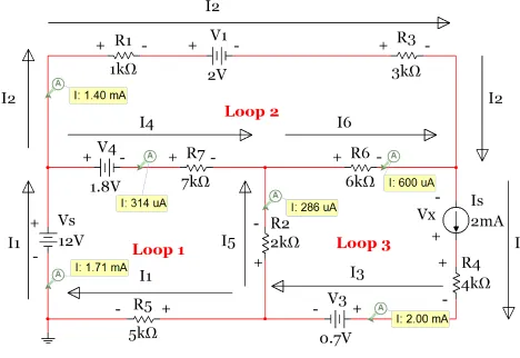
[image:35.612.74.542.174.496.2]Example 1.21) Write the 7 KVL equations for the following circuit in terms of the current, voltage, and resistor labels. Current probes are placed on each of the 6 different currents. These probes determine the correct direction of the current so the + and - signs placed on each of the elements are known to be correct. However, using Multisim to determine the current directions is NOT REQUIRED. You can assume any direction you want and if the answer comes out negative you just need to reverse the direction that you originally assumed.
Figure 1.21: Circuit for Example 1.21
For each of the equations below I will start and stop at the bottom left location of the loop. KVL_loop1: – Vs + V4 + I4∙R7 – I5∙R2 + I1∙R5 = 0
KVL_loop2: + I2∙R1 + V1 + I2∙R3 – I6∙R6 – I4∙R7 – V4 = 0 KVL_loop3: + I5∙R2+ I6∙R6 – Vx + I3∙R4 + V3 = 0
35
Section 1.4 – Kirchhoff’s Current Law (KCL) and Current Divider Rule (CDR)
Kirchhoff’s Current Law (KCL) is defined as:
[1.17]
∑ 𝐼𝐼
𝐼𝐼𝑁𝑁_𝑏𝑏𝑑𝑑𝑎𝑎𝑚𝑚𝑠𝑠ℎ=
∑ 𝐼𝐼
𝑂𝑂𝑂𝑂𝑇𝑇_𝑏𝑏𝑑𝑑𝑎𝑎𝑚𝑚𝑠𝑠ℎor
∑ 𝐼𝐼
𝐼𝐼𝑁𝑁_𝑚𝑚𝑎𝑎𝑠𝑠𝑠𝑠=
∑ 𝐼𝐼
𝑂𝑂𝑂𝑂𝑇𝑇_𝑚𝑚𝑎𝑎𝑠𝑠𝑠𝑠Unlike KVL there are not a set of rules when writing KCL equations. You only have to assume the directions of all of the current at the branch or node. If the equations yield a negative current result then the assumed direction was wrong. The direction can be changed, but the problem doesn’t need to be reworked.
The version of equation 1.17 on the left side states that the sum of currents going into a branch is equal to the sum of currents going out of a branch. This version of KCL is much easier to understand since the branch is a single point and it is not very difficult to determine which currents are connected to the branch. A simple example of KCL at a branch can be shown by solving the circuit from example 1.16 where the Reduce and Return Method was used.
Example 1.22) In example 1.16 in section 1.2 the Reduce and Return Method utilizing KCL to solve for the current through R4 and R5 was mentioned. In this example the KCL equations at each of the top
branches labeled as B1 and B2 are written and used to solve for the current through R4 and R5. Assume you already know the values calculated from example 1.16 (i.e. IR1 = 3.99 mA→, IR2 = 0.7575 mA↓, IR3 =
3.03 mA↓).
Figure 1.22: Circuit for Example 1.22
KCL at Branch B1: ∑ 𝐼𝐼𝐼𝐼𝑁𝑁=∑ 𝐼𝐼𝑂𝑂𝑂𝑂𝑇𝑇 → 𝐼𝐼𝑅𝑅1= 𝐼𝐼𝑅𝑅2+ 𝐼𝐼𝑥𝑥 → 3.99 𝑚𝑚𝐴𝐴=0.7575 𝑚𝑚𝐴𝐴+ 𝐼𝐼𝑥𝑥
→
𝐼𝐼𝑥𝑥 =3.2325 mA
KCL at Branch B2: ∑ 𝐼𝐼𝐼𝐼𝑁𝑁=∑ 𝐼𝐼𝑂𝑂𝑂𝑂𝑇𝑇 → 𝐼𝐼𝑥𝑥 = 𝐼𝐼𝑅𝑅3+ 𝐼𝐼𝑅𝑅4→3.2325 mA=3.03 𝑚𝑚𝐴𝐴+ 𝐼𝐼𝑅𝑅4
→
𝐼𝐼𝑅𝑅4=𝟏𝟏.𝟐𝟐𝟏𝟏𝟐𝟐𝟓𝟓𝒎𝒎𝒎𝒎
This answer agrees with result obtained in example 1.18 where KVL was used to solve for IR4.
36
Example 1.23) Repeat example 1.22 using KCL at nodes.
Figure 1.23: Circuit for Example 1.23
KCL at Node X: ∑ 𝐼𝐼𝐼𝐼𝑁𝑁=∑ 𝐼𝐼𝑂𝑂𝑂𝑂𝑇𝑇 → 𝐼𝐼𝑅𝑅1= 𝐼𝐼𝑅𝑅2+𝐼𝐼𝑅𝑅3+ 𝐼𝐼𝑅𝑅4→3.99 𝑚𝑚𝐴𝐴=0.7575 𝑚𝑚𝐴𝐴+3.03 𝑚𝑚𝐴𝐴+ 𝐼𝐼𝑅𝑅4
𝐼𝐼𝑅𝑅4=
𝟏𝟏
.𝟐𝟐𝟏𝟏𝟐𝟐𝟓𝟓𝒎𝒎𝒎𝒎This answer agrees with the previous example. By