manufacturing method
David J. White
Iowa State University
Follow this and additional works at:
http://lib.dr.iastate.edu/patents
Part of the
Civil Engineering Commons
This Patent is brought to you for free and open access by the Iowa State University Research Foundation, Inc. at Iowa State University Digital Repository. It has been accepted for inclusion in Iowa State University Patents by an authorized administrator of Iowa State University Digital Repository. For more information, please [email protected].
Recommended Citation
White, David J., "Polymer mortar composite pipe material and manufacturing method" (2011).Iowa State University Patents. 67.
includes waste, chemically unmodified PET material, one or more waste filler materials (e.g. rock crusher
fines, lime sludge or waste coal combustion by-products), and fiber reinforcement (e.g. glass, metal, ceramic,
carbon, organic, and polymer fibers) and wherein the PET material is melted and mixed in a container to
disperse filler material and fiber reinforcement in the PET material. The resulting mixture can be formed into a
tubular pipe shape using the plunger-cast manufacturing method and system wherein a plunger piston and
inner collapsible mold are pushed into the melted composite material contained in an outer mold. When
cooled and solidified in the mold, a composite material having a matrix comprising PET with filler material
and fiber reinforcement distributed in the matrix is formed in the shape of a tubular body.
Keywords
Civil Construction and Environmental Engineering
Disciplines
Civil Engineering
METHOD 4,356,281 A 10/1982 Brink et al. . 524/397 4,621,787 A * 11/1986 Westberg . . . .. 249/63 (75) Inventor: David J. White, Ames, IA (US) 4,852,630 A * 8/1989 Hamajima et al. . .. 164/761
5,279,491 A * 1/1994 VanAckeren .. 249/141
(73) Assignee: Iowa State University Research Foundatlon’ Inc" Ames’ IA (Us) . 6,808,154 B2 * 10/2004 Koren ... .. 249/63 , , Q1 ie a . ~~~~~ ~'
( * ) Notice: Subject to any disclaimer, the term of this FOREIGN PATENT DOCUMENTS
patent is extended or adjusted under 35 JP 5767654 A 4/1982
U.S.C. 154(b) by 0 days. JP 2001240732 9/2001
(21) Appl. No.2 12/657,681 OTHER PUBLICATIONS
Hackbarth, Composite pipe material from PET and coal combustion, (22) Filedi Jall- 26, 2010 Masters Thesis, Iowa State University, 2002, pp. 1-151.
(65) Prior Publication Data (Continued)
Us 2010/0133726 A1 Jun- 3, 2010 Primary Examiner * Joseph Del Sole
A'zzE'iK'blAStart
Related US. Application Data “13 an xammer 1m er y WV
(62) Division ofapplicationNo. 11/029,184, ?led on Jan. 4, (57) ABSTRACT
2005, now abandoned Composite material and plunger-cast pipe manufacturing
(60) Provisional application NO_ 60/534,440’ ?led on Jan method and system Wherein the composite material includes
6 2004 Waste, chemically unmodi?ed PET material, one or more
3 Waste ?ller materials (eg rock crusher ?nes, lime sludge or
Waste coal combustion b - roducts , and ?ber reinforcement
(51) Int. C]. y P
B29C 43/04
(200601)
(e.g. glass, metal, ceramic, carbon, organic, and polymer
(52) us. Cl. ... .. 264/323- 264/320 ?bers) and wherein the PET material is melted and mixed in
(58) Fi 61 d of Classi?cation Search ,2 6 4 623 a container to disperse ?ller material and ?ber reinforcement 264626: ' 153 127’ in the PET material. The resulting mixture can be formed into
See application ?le for Complete gearch hist’ory ’
a tubular pipe shape using the plunger-cast manufacturing
method and system Wherein a plunger piston and inner col
(56) References Cited lapsible mold are pushed into the melted composite material
U.S. PATENT DOCUMENTS
795,518 A * 7/1905 Lamp ... .. 249/139
1,171,641 A * 2/1916 Priest .... .. 249/112 2,731,067 A * 1/1956 Miller .... .. 156/190 3,192,569 A * 7/1965 Knabel ... .. 425/586
contained in an outer mold. When cooled and solidi?ed in the
mold, a composite material having a matrix comprising PET
With ?ller material and ?ber reinforcement distributed in the matrix is formed in the shape of a tubular body.
?y ash wastes, J. Mat. Sci. Letters, 15, 1996, pp. 1273-1275. Alkan, et al., A study on the production of a new material from ?y ash and polyethlene, Published by Elsevier in “Resources Conservation and Recycling,” 13, 1995, pp. 147-154.
White, A composite building material from ?y ash and recycled polyethylene terephthalate (PET); Abstract submitted to Conference
in Las Vagas, Apr. 30, 1998, 2 pages.
Li, et al., Composite material from ?y as and post-consumer PET, Published by Elsevier in “Resources, Conservation and Recycling,” 24, 1998, pp. 87-93.
White, Microstructure of composite material from high-lime ?y ash
and RPET, J. of Materials in Civil Eng., Feb. 2000, pp. 60-65.
Research Center, Overview of Project, Mar. 1994-Mar. 1995.
RebeiZ, et al., Thermal properties of polymer mortar using recycled
PET and ?y ash, J. of Mat. in Civil Eng., May 1995, pp. 129-133.
RebeiZ, et al., Strength Properties of Polyester Mortar using PET and Fly Ash Wastes, J. of Energy Eng., Apr. 1996, pp. 10-21.
Lewis, Richard J ., Sr. (2002). Hawley’s Condensed Chemical Dic
tionary (14th Edition). John Wiley & Sons. Online version available
at: www.knovel.com/web/portal/browse/display?iEXTi
KNOVELiDISPLAYibookid:704&VerticalID:0,“Fly Ash”.
22
?aw
FIG.3A
FIG. 3D
L
R~
i
I“
|l|
FIG.3B
14L©R
[image:7.614.114.473.125.706.2]FIGSA
/
(C(@
22
14
12
226 V
>
:3
FIG. 6
3O
--/_
IIIIIZ
30
own/
FlG.7
E25 59.3 =5 5Q 33 8.5%
[image:15.614.181.437.120.704.2]0,020 0.025 0.030
FIG. 11A
0.010 0.015
Strain (AD/D)
0.005 0.000
—- FSC: 50% Filler. 3% Fibers
1' FBC: 60% Filier. 3% Fiber: ——- F86: 67% Filler, 3% Fibers 100
150%
A825 593 =5 .8 83 8.5%
FIG. 11B
0402 0.03
Strain(AD/D) 0.01 0100
mmm
enme
mluFnm
Fun-Ll
%5%
334
marl.
IE“ I”
HRH
0
%%%
3
00 a. . _SSS
_
LLuL
~
_ _n_ \
_ \ _ _ f
021/
\ I \ /\ ll I
/
_
/////1
_ If / / .I l/ / // /
/
//
ll
/ / / l /
//
//
I/I,
w w m52% £62 :5 ma RS 33%
0.04
8.02
0.01 0.63 0.05 0105
Strain (AD/D)
FIG. 1 1 C
PFA: 50% F?ler, 3% Fibam
[image:16.614.167.443.105.701.2]Ewes 593 .E: 5Q 33 8:34
FIG. 11D
0.03
0.02 0.01
0.00
Strain (AD/D)
RCF: 50% Filler. 3% Fibers
59
m w w w
Aéza 593 E5 an 33 35%
FIG. 11E
0.05
0.03 0.04
Strain (AD/D)
0.02 0101 6.00
CPBBA: 50% Filler. 3% Fibers
0910 6.608
G504 .
525 59.3 a5 an D84 8.5%
. - ~ .
Q 0 o c 0 U
FIG. 11F
0.005
Strain (AD/D)
0.030 0.025 0.020 0.015 0.0l0 m
m m m
E25 52.3 :5 .8 B3 3.22.
[image:17.614.176.425.126.708.2]0.000 0005
FIG. 11G
Strain (40m)
— SF,“ 50% Filer. ass Fberl
0.03
051
min
Straln (ADD)
. . 4 . _
m m m m 5
E25 593 =5 .8
33 “.892
FIG. 1 1H
0.00
-- samsms Film. 315 Flbcri
0.035 0.020 0.01 5 0.010 0.005 .m. m." w .h.
E22. 523 =5 .8
B3 3.52
0.035 0.000
Strain (ADD)
P1as?c:0% Filler, 3% Fibers
.
S
20
15
18 -
.5? 593 $5 an E3 352.
0.85
0.04
0.02 0.03
Strain (ADID)
[image:18.614.105.483.182.538.2]090
FIELD OF THE INVENTION
The present invention provides polymer mortar composite
materials including recycled, post-consumer Waste polyeth
ylene terephthalate (PET) With Waste ?ller materials and ?berreinforcement and methods of their manufacture and methods of their use as pipe in the construction industry.
BACKGROUND OF THE INVENTION
Diverting solid Waste from land?lls is increasingly impor
tant due to limited availability of land?ll space, rapidly increasing land?ll cost, and environmental threats. The US.
is the largest global producer of PET containers at nearly 70 percent of the supply [reference 1]. In the U.S., estimates
indicate that annual production of PET containers Will reach more than 2 million tons [reference 2]. The recycling rate for PET is about 25 percent [reference 3]. Production of the Waste ?ller materials is about 500 million tons for rock quarry crusher ?nes, 10 million tons of lime sludge, and 100 million
tons for coal-combustion by-products. Recycling has
emerged as the most practical method to deal With these
high-volume Waste problems.
In addition, the US. has about 19,782 seWerage systems
serving about 170 million people or about 75 percent of the
population [reference 4]. As With much infrastructure in this
country, this subterranean component has also deteriorated
due to normal aging, sulfuric acid degradation, under design,
poor initial design, and minimal maintenance. It is estimated that 800,000 miles of sanitary seWer line in the US. are in need of rehabilitation and that We are currently making repairs at the rate of 2 percent per year [reference 5]. Sixteen
thousand miles of rehabilitation With an estimated 8 thousand
miles of neW construction create a need for improved pipe material.
An object of the invention is to provide a polymer mortar
composite pipe material that has several bene?cial material
properties over conventional Portland cement concrete (PCC)
pipe and vitri?ed extra strength clay tile including high struc
tural capacity, excellent acid resistance, and loW density. Equally important is the fact that the material components of the polymer mortar composite formulation consist of recycled plastic and Waste ?ller materials (rock quarry crusher ?nes, lime sludge or various coal combustion byproducts). By using recycled, post-consumer Waste polyeth
ylene terephthalate (PET) instead of virgin plastic, Which is
petroleum derived material; use of a signi?cant volume ofcrude oil can be reduced.
Another object of the invention is to provide a plunger-cast manufacturing method and system than can increase recy
cling through production of polymer mortar composite pipe
using the composite material mixtures described herein.
Still another bene?t of the invention derives from produc
tion of the polymer mortar pipe to provide a strong, light
Weight, and durable pipe product for Which there is currently
tremendous need.SUMMARY OF THE INVENTION
The present invention provides a composite material and
plunger-cast pipe manufacturing method and system Wherein
20 25 30 35 40 45 50 55 60 65
can be formed into a tubular pipe shape using the plunger-cast
manufacturing method and system pursuant to an embodi ment of the invention Wherein a piston and an inner collaps ible mold thereon are pushed into the melted composite mate
rial contained in an outer mold. When cooled and solidi?ed in
the mold, a composite material having a matrix comprising
PET With ?ller material and ?ber reinforcement distributed in the matrix is formed in the shape of a tubular body. The
plunger-cast pipe manufacturing method and system can be
used With other materials as Well and is not limited to the
composite material described above.
In one embodiment of the invention, the solid Waste,
chemically unmodi?ed PET material, Waste ?ller particles
and ?ber reinforcement are premixed and placed in a melting container for melting of the PET material While the mixture is mixed or stirred. Alternately, the solid Waste, chemically unmodi?ed PET material can be melted in the container, and pre-heated Waste ?ller particles introduced to the melted PET
material With the mixture stirred or mixed. Once the PET/
?ller mixture is homogenized, the ?ber reinforcement is incrementally added to the mixture and stirred or mixed. The mixture of melted PET material, Waste ?ller particles and
?ber reinforcement can be molded, extruded or otherWise
formed.
The invention envisions use of Waste PET material from
recycled beverage bottles and other sources. In practice of the invention, the recycled Waste PET material is not chemically modi?ed in any Way prior to melting. The solid recycled
Waste PET material may be Washed in tap Water and shredded or otherWise comminuted prior to melting.
The invention envisions use of different types of one or more Waste ?ller materials including rock quarry crusher
?nes, lime sludge and/ or coal-combustion byproducts and/or other Waste ?ller materials With comparable morphological
characteristics.
Various amounts of ?ller material up to about 70 percent
(based on Weight of PET) in combination With various
amounts of ?ber reinforcement up to about 6 percent (based on Weight of PET and Waste ?ller) can be included in the composite material. Preferably, the Waste ?ller content of the composite material is at least about 50 percent and ?ber content preferably from about 1 to about 4 percent.
In another illustrative embodiment of the invention, the
melted and mixed composite material (or other ?oWable material) is formed into a tubular pipe using a plunger-cast
manufacturing method and system. In practice of an illustra
tive method embodiment of the invention, a piston plunger,
base plate, outer rigid cylinder mold, and inner collapsible
mold are ?rst preheated in an oven to about 2700 C. The
plunger piston preferably is a specially shaped, beveled
plunger piston attached to a hydraulic piston. The inner col lapsible mold is attached to the plunger piston. The base plateand outer rigid mold are placed under the piston and the
melted composite material is introduced into the outer rigid
mold and base plate. The inner mold includes a transverse dimension, such as diameter, that is smaller than that of the
outer mold so as to form a space therebetWeen When the inner
the inner mold is fully positioned or inserted into the outer
mold, the plunger piston is removed leaving the inner collaps
ible mold in place forming the inner wall of the pipe. During curing of the composite material, the inner mold can collapse,thus allowing for thermodynamic shrinkage of the composite
material. Fiber reinforcement signi?cantly reduces deleteri ous shrinkage cracks from forming during the cooling process. Once the pipe has cooled enough to solidify, it is
removed from the mold and further cooled at room tempera
ture. The plunger-cast manufacturing method and system is
then reused to manufacture additional tubular pipe sections.
The above objects and advantages of the invention will become more readily apparent from the following detailed
description taken with the following drawings.
DETAILED DESCRIPTION OF THE DRAWINGS
FIGS. 1A, 1B, and 1C are photographs of three forms of
solid waste, post-consumer recycled PET beverage bottle
material.
FIGS. 2A, 2B are photomicrographs of ?ber reinforcement
with waste ?ller material (rock quarry crusher ?nes desig
nated RCF) and FIG. 2C is a photomicrograph of the particle distributions of the waste ?ller material (RCF).
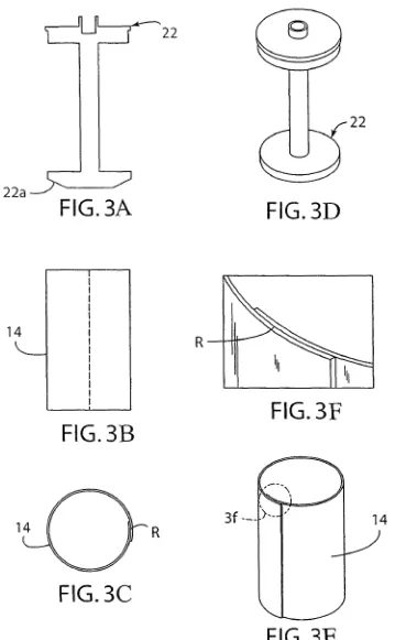
FIG. 3A is a side elevation of the plunger piston. FIG. 3B is
a side elevation of the collapsible inner mold. FIG. 3C is a
plan view of the inner mold. FIG. 3D is a perspective view of
the piston. FIG. 3E is a schematic perspective view showing the inner collapsible mold. FIG. 3F is a schematic partial
enlarged perspective view of the inner collapsible mold edges
overlapped and encircled in FIG. 3E.FIG. 4A is a schematic elevational view of outer rigid
mold. FIG. 4B is a schematic elevational view of the bottom
plate on which the outer mold sits. FIG. 4C is a plan view of the bottom plate. FIG. 4D is a perspective view of the outer mold. FIG. 4E is a perspective of the bottom plate.
FIG. 5A is an exploded schematic view of components of the plunger-cast manufacturing system. FIG. 5B is an
exploded schematic view of the plunger piston having the
inner mold thereon and the outer rigid mold located below theassembled plunger piston and inner collapsible mold.
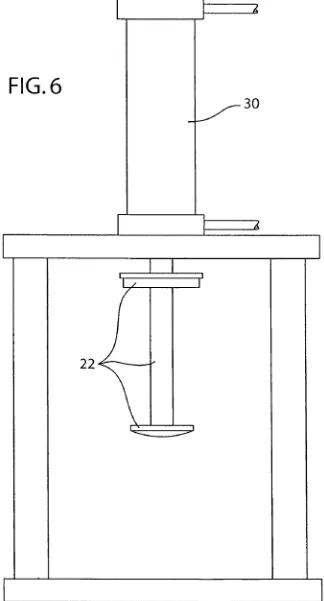
FIG. 6 is a side elevation of the plunger piston connected to hydraulic ram
FIG. 7 is a side elevation of the inner collapsible mold
attached to plunger piston and base plate with outer mold
FIG. 8 is a perspective view of the plunger-cast mold after
the plunger piston has been extracted
FIG. 9 is a perspective view of the plunger cast composite
pipe specimen
FIG. 10 is a perspective view of the ultimate three-edge
bearing test setup.
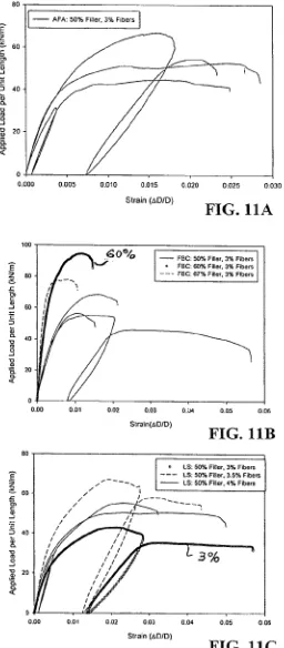
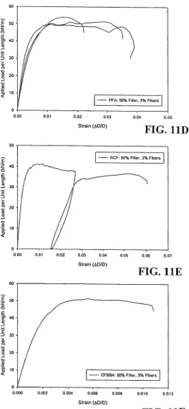
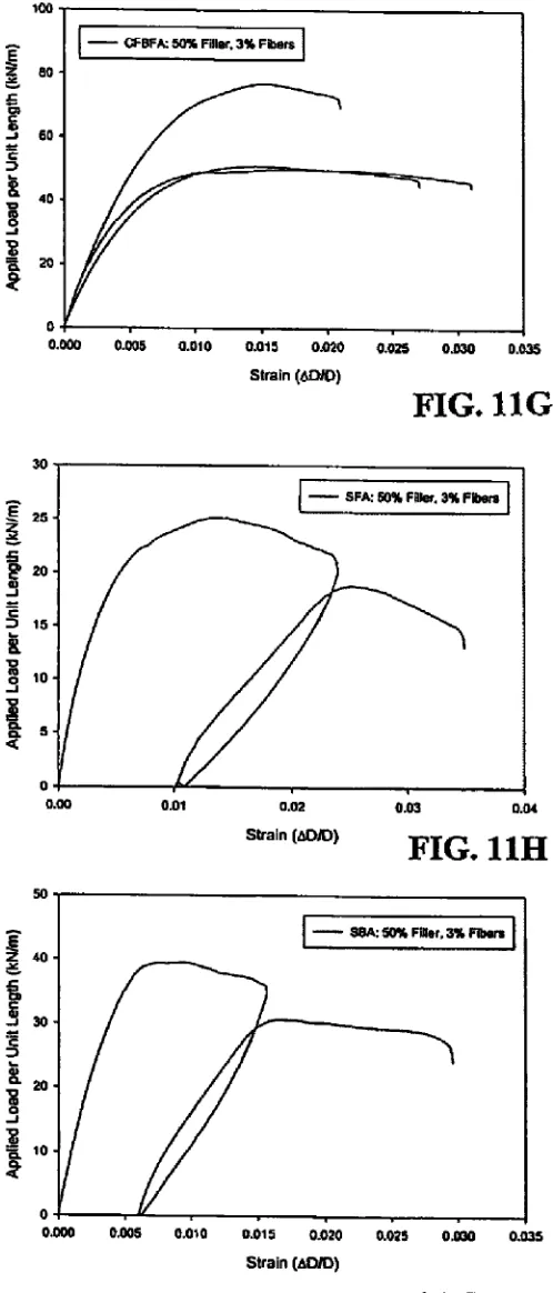
FIGS. 11A through 11] are graphs of applied load versus
strain of the ultimate three-edge bearing strength tests.
DETAILED DESCRIPTION OF THE INVENTION
The present invention will be described ?rst with respect to
making a composite material using solid waste, post-con
sumer recycled PET material and waster ?ller materials and discontinuous reinforcement ?bers. Next the engineering
properties of the composite material will be described, and
?nally the plunger-cast manufacturing process and ultimate
three-edge bearing strength tests for pipe specimens will be
presented, all for purposes of illustration and not limitation.20 25 30 35 40 45 50 55 60 65
material and are available in three forms: (Type 1) sorted,
washed and processed; (Type 2) unsorted and shredded; and
(Type 3) partially-sorted, shredded and washed. Flaked orpelletized PET commonly available from plastic recycled
facilities is referred to as “Type 1”. PET collected in the form of waste beverage containers that have been shredded withoutremoving the labels or caps and no washing is referred to as
“Type 2”. PET collected in the form of waste beverage con tainers that have been shredded after removing some of the
labels and caps and washing in a water bath is referred to as
“Type 3”. FIGS. 1A, 1B, and 1C show the three forms Type 1,
Type 2, Type 3, respectively, of post-consumer recycled PET
beverage bottle material used in the production of compositematerial pursuant to an illustrative embodiment of the inven
tion offered for purposes of illustration and not limitation. Waste Filler Materials
Several types of waste ?ller materials can be used in the
composite material mixture including: (1) rock quarry
crusher ?nes (RCF); (2) coal-combustion by-products
(CCBs); and (3) lime sludge from water treatment plants(LS). Table 1 summarizes the chemical constituents and
physical properties for all waste ?ller materials used in examples described below.
Rock Quarry Crusher Fines
Of the 2-billion tons of aggregate produced per year in the US. [reference 6], it is estimated that an additional 25 percent to 30 percent is wasted due to crushing and screening opera
tions. The screening materials (typically 100 percent passing
9.5 mm sieve and up to about 30 percent passing the 0.075mm sieve) are often stockpiled or put back into the quarry as
?ll, resulting in zero or negative value. The rock quarry
crusher ?nes used in the examples below comprised crushed
quartzite. 100 percent of the particles were smaller than 0.15
mm and 74 percent smaller than 0.075 mm. Minerals identi
?ed in the rock quarry crusher ?nes consisted of quartz,
kaolinite, and talc.
Lime Sludge
Most drinking water is softened and most commonly lime softening is used, introducing slaked lime to remove hardness as calcium carbonate and magnesium hydroxide. About 10
million tons of lime sludge is generated in the US. annually, which creates disposal problems. Lime sludge has very simi
lar chemical composition as limestone. 100 percent of the lime sludge used in the examples below was smaller than
0.075 mm. The only mineral identi?ed in the lime was calcite.
Coal Combustion By-Products
Coal combustion by-products are produced from burning
coal in energy production facilities and exist in a wide range
of gradations and chemical compositions. About 100 million
tons of coal combustion by-products are produced in the US.
annually [reference 7]. Six different coal combustion by
products were evaluated in this study including: (1) PrairieCreek ?y ash (PFA); (2) Ames ?y ash (AFA); (3) Iowa State
University (ISU) circulating ?uidized bed ?y ash (CFBFA);
(4) ISU stoker ?y ash (SEA); (5) ISU circulating ?uidized bed
bottom ash (CFBBA); (6) ISU stoker bottom ash (SBA); and (6) University of Northern Iowa (UNI) ?uidized bed combus tion residue (FBC).PFA is produced form burning coal originating from the Powder River Basin in Wyoming and is burned in pulverized
boilers. All particles are smaller than 0.85 mm and 93 percent are smaller than 0.075 mm. PFA classi?es as an ASTM C618
CFBFA and SFA Were both supplied by ISU PoWer Plant, Which burns a mixture of coal from Illinois and Kentucky. The
same mixture of coal is burned in tWo different types of boilers. The ashes receive their names from the boilers in
Which they are produced, circulating ?uidized bed and stoker boilers, respectively. SFA has the highest loss on ignition
(LOI) at 42.4 percent due to inef?cient combustion. All
CFBFA particles are smaller than 0.25 mm and 89 percent are smaller than 0.075 mm. All particles in SFA are smaller than 2.00 mm and 93 percent are smaller than 0.075 mm. Minerals
identi?ed in the CFBFA are quartz, anhydrite, lime, hematite,
and illite. Minerals identi?ed in the SFA are quartz, mullite,
hematite, and albite.
CFBBA material has particles With 99 percent smaller than 4.75 mm and only 1 percent smaller than 0.075 mm. Quartz,
anhydrite, lime, hematite, calcite, and portlandite are the min
erals identi?ed in the CFBBA.
Due to large particle sizes, SBA Was ?rst crushed so that all
particles are smaller than 2.0 mm and 28 percent are smaller
than 0.075 mm. Quartz, mullite, Magnetite, and hematite are the minerals identi?ed in the SBA.
FBC Was supplied by the UNI PoWer Plant, Which burns a
mixture of coal from Kentucky and West Virginia. A
pyropoWer boiler is used to burn the coal at this location. All
particles are smaller than 2.0 mm and 64 percent are smaller than 0.075 mm. Minerals identi?ed in the FBC are lime,
anhydrite, quartz, and hematite.
Fiber Reinforcement
Fiber reinforcement is added to the composite material to
improve its engineering properties and control thermody
namic shrinkage. Fiber reinforcement can include one or
more of glass, metal, ceramic, carbon, organic, and polymer
?bers. For the examples described beloW, discontinuous?berglass ?bers of different lengths (6 mm and 13 mm) Were used. The ?bers Were both chopped strand 919-4 CT ?ber
glass ?bers produced by Vetrotex America, Inc. (Product Nos.
CA4J919022 and CA4J919053, respectively). Fiber reinforcement is an essential component of the composite mate
rial for production of the plunger-cast tubular pipe specimens,
as Without ?bers, thermodynamic shrinkage cracks develop during the cooling process. Further, the ?ber reinforcementenhances uniform distribution of air voids.
Manufacturing Process for Composite Material
Manufacturing of the composite material is initialed by Weighting out the desired post-consumer PET material (Type
1, 2 or 3), the Waste ?ller material, and ?ber reinforcement. The post-consumer PET is introduced into an electric melting pot and then pre-heated Waste ?ller material is added and mixed With the melted PET. The po st-consumer PET, Which is
a thermoplastic, melts at about 2700 C. The ?ller material can
alternately be added to the melted PET prior to heating. A
mechanical stirring device (steel rod or spatula) is used to mix the PET and Waste ?ller materials. Once mixed, the ?ber
reinforcement is incrementally added and mixed until evenly dispersed in the mixture.
Specimens for engineering property evaluation are pre
pared by transferring the composite mixture into preheated
mold of the desired geometry and alloWing the mixture tocool at room temperature.
20 25 30 35 40 45 50 55 60 65
pressive Strength of Cylindrical Concrete Specimens [refer
ence 8] Was used as a guide to test the compressive strength
for the composite cylinder specimens.A Soiltest machine Was used to produce the compressive force. The smallest division
on the testing machine Was 0.2 kN. Loading rate Was calcu
lated by measuring the elapsed time for increment 2 kN. The
load of 2 kN Was then divided by the initial cross-sectional
area to determine the compressive strength. Compressive
strength Was then divided by the elapsed time in seconds to determine the loading rate.
Test specimens Were constructed from different composite
mixtures. TWo cylinder specimens from every composite
design mix Were tested. Test specimens had a diameter of
about 50.8 mm and a length of 101.6 mm. Load rate Was
continuous and Without shock and Within the range of 0. 1 5 to 0.35 MPa/s. The diameter of the cylinder specimens Was determined by averaging tWo diameters in the middle of the
specimen at right angles from each other. Lengths of the cylinder specimens Were determined by averaging tWo
lengths.
Cylinder specimens Were positioned by centering them
vertically on one of their ends in the middle of the bearingblock. The ram Was then loWered so that it came into contact
With the top end of the cylinder specimen. The testing
machine Was set to controlled test, Which started the loading.Loading continued until the load indicator decreased signi? cantly. This decrease indicated that the cylinder specimen
failed. The maximum load Was then recorded to the nearest
0.2 kN division. The testing machine Was then unloaded and the sample removed. This process continued until all of the
cylinder specimens Were tested.
Results indicate that the average compressive strength for 96 specimens is 38.8 MPa, Which is slightly greater than the
ordinary PCC strength of 15 to 35 MPa. Elastic modulus
varied from 1300 MPa to 5700 MPa. The average elastic
modulus Was 3300 MPa (24 specimens), Which is 7 to 10
times loWer than ordinary PCC. Density of the composite ranged from 1.2 to 1.8 g/cm3 With an average of 1.6 g/cm3,
Which is loWer than ordinary PCC densities of 1.9 to 2.5
g/cm3. Statistical analyses shoW that compressive strength,
elastic modulus and density increase With increased ?ller and
?ber reinforcement content.
Tensile Strength
ASTM C 496-96 Standard Test Method for Splitting Ten
sile Strength of Cylindrical Concrete Specimens [reference 9]
Was used as a guide to test the tensile strength for the com
posite cylinder specimens. A Soiltest machine Was used to
produce the compressive force.
Bearing strips Were constructed from 6.4 mm thick oak
plyWood. Widths of the plyWood bearing strips Were 25 mm
and the lengths Were 114.3 mm. Supplementary bearing bar
Was constructed from a 12.7 mm thick aluminum bar. Alumi num bar had a Width of 38 mm and the length of the bar Was
114.3 mm. Test specimens Were constructed from different
composite mixtures and had diameters of 50.8 mm and
lengths of 101.6 mm. 152 mm diameter steel spacer blocks
Were used as the loWer bearing platform.
from each end and one in the middle of the cylinder speci
mens. Lengths of the cylinder specimens Were determined by
averaging tWo lengths.
Cylinder specimens Were positioned by centering one ply
Wood strip on the loWer bearing platform lengthWise and placing the cylinder specimen lengthWise so that the centerline Was vertically over the center of the Width of the plyWood
strip. Then the top plyWood strip Was placed over the cylinder
specimen lengthWise and centered over the centerline. The upper bearing bar Was then centered over the top plyWood
strip. The ram Was loWered so that it came in contacted With
the upper bearing bar. The cylinder specimen, plyWood strips,
and upper bearing bar Were then aligned and centered.The testing machine Was then set to controlled test, Which
started the loading. Loading continued until the load indicator decreased signi?cantly. This decrease indicated that the cyl
inder specimen failed. Maximum load Was then recorded to the nearest 0.2 kN division. The testing machine Was
unloaded and the sample removed. PlyWood strips Were then disposed. This process continued until all of the cylinder
specimens Were tested.
Results indicate that the average splitting tensile strengths for 96 specimens is 4.3 MPa, Which is greater than the ordi
nary PCC strength of 1.5 to 3.5 MPa. Further, statistical
analyses indicate that tensile strength increases With
increased ?ller content and ?ber reinforcement content.
Durability Testing
TWo durability tests Were conducted to evaluate the com
posite mixtures under various environmental conditions simi lar to Which seWer pipes are subj ectediWater absorption and
sulfuric acid resistance. Specimens for the Water absorption
and acid resistance tests Were made by cutting discs off of
cylinder specimens.
Water absorption tests Were conducted to indicate the
amount of Water the various composite mixtures absorbed. ASTM D 570-98 Standard Test Method for WaterAbsorption
of Plastics [reference 10] Was used as a guide to test the Water
absorption of the composite specimens. 50.8 mm diameter
specimen discs Were cut off of the cylinders using a poWer
miter saW With a masonry blade to a thickness of 6 mm.
One disc for each composite mixture Was tested for Water absorption. Discs Were placed in the same container of tap Water. The disc’s Weight, thickness, and tWo diameters at a
right angle from each other Were measured prior to submerg
ing them into the Water. Discs Were placed into the Water so a
section of one part of the circumference touched the side of the container and another section of the same edge touched the bottom of the Water container. The specimen discs Were
then left alone for a period of one Week at room temperature. After one Week, discs Were removed from the Water one at a time. Surfaces of the specimen discs Were then dried With a cotton cloth rag. Their Weights Were recorded to the nearest
0.01 g and then the discs Were immediately placed back into
the Water container. The Water absorption test Was conducted
after the ?rst Week and every tWo Weeks thereafter for a period
of seven Weeks.
Results are presented in Table 3. The A symbol is the
percent difference in Water absorption betWeen composites
With ?ller and pure plastic. Positive numbers indicated that the composites With ?ller absorbed more Water than the pure
plastic. All specimens With sulfur trioxide contents higher than 12% had high Water absorption. Specimens With
20 25 30 35 40 45 50 55 60 65
Sulfuric acid, Which can be produced from bacteria in
seWage, is responsible for destroying PCC seWer pipes. For
this reason, the composite mixtures Were tested in a 10 per
cent by volume sulfuric acid and Water solution. ASTM D 543-95 Standard Practices for Evaluating the Resistance of
Plastics to Chemical Reagents [reference 11] Was used as a
guide for this procedure. Specimen discs Weights, thicknesses
at the center, and tWo diameters at right angles to each other Were measured prior to introducing them into the acid.Dimensions Were measured to at least 0.025 mm and the Weights Were measured to the nearest 0.01 grams.
Sulfuric acid Was placed into Mason canning jars and the
discs Were then submerged into the acid. Each disc Was placed in a separate jar. After placing the discs into jars, the lids Were
screWed on and the jars Were left alone at room temperature
for a period of one Week. After one Week, the lids of the jars Were removed and specimens Were taken out of the jar using tongs. Specimens Were rinsed under running tap Water to remove the sulfuric acid. Then, the surfaces of the specimen Were Wiped dry using a cotton cloth rag. The Weight, thick ness, and diameters of the specimen Were then recorded. The
specimen Was placed back into the jar and the lid screWed
doWn. Observations Were recorded on the appearance of the
specimen. These procedures Were folloWed again at tWo Week
intervals for a period of seven Weeks.
Summary of the results for the acid resistance tests are
provided in Table 4. The positive numbers indicate specimens absorbed sulfuric acid solution. The RCF and pure PET plas
tic specimens shoWed the greatest resistance to a solution of 10% sulfuric acid in these accelerated laboratory tests.
Microstructure Analysis
FIGS. 2A, 2B, and 2C shoW a sheared surface for the
composite mixture including RCF (rock quarry crusher ?nes)
?ller particles and indicates that the ?ller particles are uniformity dispersed in the mixture and that the ?ber reinforcement is breaking rather than pulling out indicating that the ?ber tensile strength is fully mobiliZed and tightly bound to the
matrix.
Plunger-Cast Pipe Manufacturing Method and Apparatus
Polymer mortar composite pipe specimens Were manufac
tured from the aforementioned composite material mixtures for purposes of illustration and not limitation. Equipment used to produce the pipe specimens included: a hydraulic ram
R, plunger piston 22, inner collapsible mold 14 having an
overlapping region R at a longitudinal slit, outer mold 12 held on a base plate 10 by tWo bolts 11 securing outer mold ?anges12f on the base plate, and concrete or steel spacers BL to rest
the base plate 10 on during cooling. The inner mold 14 has an
outer diameter smaller than that of the outer mold 12 so as to de?ne an annular space therebetWeen When the inner mold is inserted in the outer mold as described beloW. About 18,000
grams of material Was used to produce one pipe specimen With dimensions of: Wall thickness 38 mm; length 260 mm;
outside diameter 306 mm.
Before the pipe is to be manufactured, the ?ller material and molds are preheated. The desired amount of ?ller is
Weighed out then placed into an oven (not shoWn) at approxi mately 2700 C. Preheating the Waste ?ller shortens the mixing
![FIG. 11.]](https://thumb-us.123doks.com/thumbv2/123dok_us/4725.77/18.614.105.483.182.538/fig.webp)
