273 Branchport Ave.
Long Branch, N.J. 07740 Thank you for using our products. (800) 631-2148
www.wheelockinc.com
AUDIOLINK SERIES INSTALLATION INSTRUCTIONS MODEL AA-10 PAGING AMPLIFIER
Use this product according to this instruction manual. Please keep this instruction manual for future reference. GENERAL APPLICATION INFORMATION:
Wheelock's AudioLink Series Model AA-10 Paging Amplifier is output rated at 10 watts RMS.
This amplifier affords a choice of three different inputs: one low impedance microphone input, one telephone paging input, and one high impedance auxiliary input. Three input channels allow these inputs to be used actively at one time: one microphone input, a telephone paging input, and one auxiliary input. Note that the auxiliary input (i.e., background music, tone generator, etc) will automatically be soft muted whenever a telephone page is generated or a microphone is used. After completion of the page, the music will rapidly return to its original level.
A built-in limiter circuit compensates for the varying voice levels and paging styles of the people who have access to telephone paging or a microphone. The limiter maintains rated output without distortion.
The amplifier features tamper-resistant individual input volume controls, as well as a master volume control, individual treble and bass controls, a low-cut horn protect switch, power on indicator, and a peak level indicator.
The unit operates from 115 volts, 60Hz and has a power consumption of 35 watts. The unit has a thermal breaker in the power transformer as well as thermal cut-off and current limiting for overload protection on the output. The thermal breaker in the transformer is automatically resettable.
NOTE: All CAUTIONS and WARNINGS are identified by the symbol . All warnings are printed in bold capital letters.
CAUTION: In the event the transformer's thermal breaker does not reset, have the trouble investigated by an authorized service technician or return unit to the factory.
WARNING: TO REDUCE THE RISK OF FIRE OR ELECTRIC SHOCK, DO NOT EXPOSE THIS UNIT TO RAIN OR MOISTURE.
UNPACKING:
The amplifier was carefully checked before leaving the factory. Inspect shipping container and unit carefully for indication of improper handling. If the unit has been damaged, make an immediate claim to the carrier.
MOUNTING INSTRUCTIONS:
The amplifiers are designed for either shelf or wall mounting. For surface wall mounting, use the 2 keyhole slots in the chassis cover. Be sure to use hardware suitable for the mounting surface. Do not block air flow to top or bottom. Blocking the air flow will cause automatic thermal shutdown.
CAUTION: These devices are not intended for use in hazardous locations as defined by the National Electrical Code (NEC) and by the National Fire Protection Association (NFPA).
WARNING: DO NOT USE THIS UNIT IN LIFE-SAFETY APPLICATIONS. THIS UNIT IS UL 813 LISTED AND CUL LISTED FOR COMMERCIAL AUDIO ONLY.
POWER AND GROUNDING:
TECHNICAL SPECIFICATIONS:
# PARAMETERS AA-10 TOLERANCE COMMENTS
1 Power Output
@ 1KHz 10 Watts RMS ±1dB @ 115VAC/60Hz ±5%
2 Total Harmonic
Distortion Less than 1% THD +1%
Same as above @ rated output
3 Outputs 8 OHMS, 25V, 70.7V ±1.5dB Bal. or Unbal.
INPUTS TELEPHONE MIC AUX --- ---
4 Impedance 600 OHMS 600 OHMS 12K OHMS --- @ 1kHz
5 Sensitivity
-20dBM (77.5mV -
-16 +20) 1mV 220mV
TEL ±2dB MIC ±.5mV AUX +20% -50%
To produce rated output 6 Frequency
Response
300Hz-5kHz 50Hz-15kHz 50Hz-15kHz ±3dB Ref. 1kHz @ 1W
25kHz MAX. 7 Signal to Noise
Ratio 65dB 60dB 70dB -4dB +10dB Not Weighted
8 Type of Input Transformer Isolated/Bal. Balanced or Unbalanced Unbalanced --- ---
9 Controls TEL, MIC, AUX, BASS, TREBLE, MASTER VOLUME Front Panel Mount
Lo cut switch Front Panel Mount
10 Indicators Green LED - Power ON
Red LED - Peak Level Front Panel Mount
11 Protection Transformer thermal circuit breaker, no-load, low-load, short circuit and
thermal overload protection on output and supply regulators. ---
# PARAMETERS AA-10 TOLERANCE COMMENTS
12a Treble Control -10.5dB TO +10.5dB @ 12kHz ±4dB ---
12b Bass Control +10.5dB TO -10.5dB @ 100Hz ±4dB ---
13 Lo-Cut Switch -6dB @ 250Hz +1dB -2dB ---
Automatic 14 Limiter for paging
± 4dB output level maintained without clipping, even while exceeding
rated input level up to 20dB. --- Paging inputs
Automatic 15 Mute
Operation Output level 1 watt for 40dB muting Min.
Mute of music Output while page
Is activated 16 Regulation No load to full load output Less than 2dB --- Stability of amp. With or
Without load 17 RFI Protection Rfi test: use CB transmitter output in same room - minimum 20ft. from amplifier. --- No pickup 18 Consumption
FRO idle
35 Watts 15 Watts
INPUT CONNECTIONS: (Figures 1 & 2)
CAUTION: Disconnect power prior to connecting or disconnecting to either the inputs or the outputs. Failure to disconnect power when connecting or disconnecting inputs or outputs could cause internal damage.
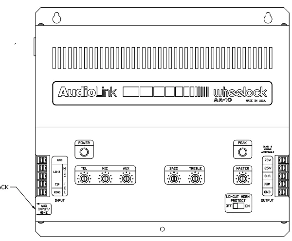
Telephone Paging Input (Figure 1): Connect telephone wires to the input screw terminals marked TIP and RING. For Tip and Ring connections to various types of telephone paging access, see Figures 4A, B & C.
Microphone Input (Figure 1): Connect balanced low-impedance microphone wires to the input screw terminals marked LO-Z. The shield must be connected to the GND screw terminals. An unbalanced microphone may be connected to the same screw terminals. However, one of the two LO-Z terminals for that input must be connected to the adjacent screw terminal marked GND. Install a jumper wire, between one LO-Z screw terminal and the GND screw terminal.
NOTE: To avoid noise pick-up, the microphone input cable should be a shielded cable, with the shield connected to the input GND terminal.
Input Connections
Figure 1. Auxiliary Inputs (Figure 2):
To connect an FM tuner, CD player, tape player, tone generator, or any other line level program source (i.e., mic/line mixer) to the AUX input jack on the side panel, use a single conductor shielded cable terminated in a standard RCA type phono plug.
AUX input is a high impedance (HI-Z) input channel.
OUTPUT CONNECTIONS: (Figure 3)
Referring To Figure 3:
Connect output wires from the speaker load, to the COM screw terminal and the selected constant voltage terminal, (i.e. 25V or 70V). The constant voltage distribution method facilitates the use of multiple speakers in parallel with a single amplifier. Note that each speaker must have its own 25V or 70V line-matching transformer. Select the wattage tap on the line matching transformer of each speaker, for the desired power.
An 8 ohm speaker load may be connected to the COM and the 8 ohm terminals. An 8 ohm speaker or an 8 ohm total speaker load rated for at least 10 watts should be used.
Proper Wire Size/Length:
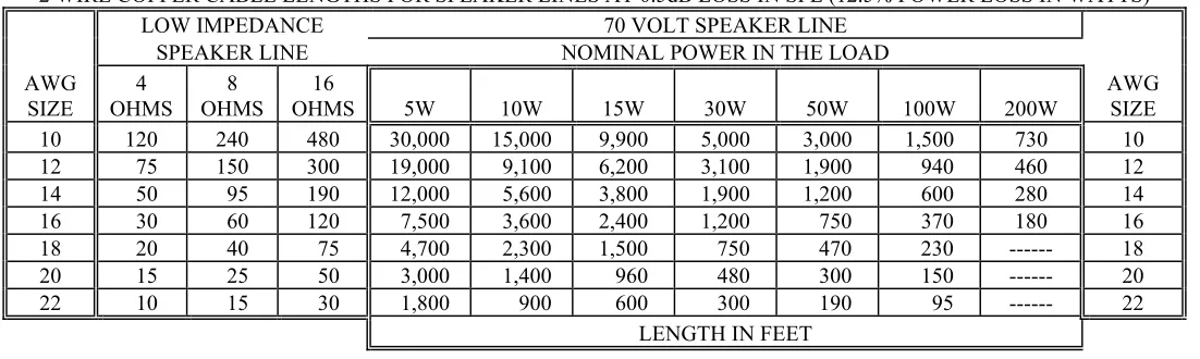
To minimize power loss in the system cabling, use a wire gauge suitable for the power being distributed and the length of cable. Use the following table as a guide:
2 WIRE COPPER CABLE LENGTHS FOR SPEAKER LINES AT 0.5dB LOSS IN SPL (12.5% POWER LOSS IN WATTS)
LOW IMPEDANCE 70 VOLT SPEAKER LINE
SPEAKER LINE NOMINAL POWER IN THE LOAD
AWG SIZE
4 OHMS
8 OHMS
16
OHMS 5W 10W 15W 30W 50W 100W 200W
AWG SIZE 10 120 240 480 30,000 15,000 9,900 5,000 3,000 1,500 730 10
12 75 150 300 19,000 9,100 6,200 3,100 1,900 940 460 12
14 50 95 190 12,000 5,600 3,800 1,900 1,200 600 280 14
16 30 60 120 7,500 3,600 2,400 1,200 750 370 180 16
18 20 40 75 4,700 2,300 1,500 750 470 230 --- 18 20 15 25 50 3,000 1,400 960 480 300 150 --- 20 22 10 15 30 1,800 900 600 300 190 95 --- 22
LENGTH IN FEET
NOTES: (1) For 25 volt line divide all 70 volt lengths by 8. (2) To allow for future expansion, and the distributed cable line loss, it is recommended that the total system wattage should not exceed 85% of the amplifier's rated output (i.e. 8.5 watts for the AA-10). (3) The total system wattage requirement is the summation of the wattage tap selections of all system speakers and horns.
Output Connections
Figure 3.
Telephone Paging Access Connections Audio Page Port
CO Line, Centrex Number Line, Or Analog Station Extension Port
(Refer to TPI-100 installation instructions for internal control settings and adjustments.)
Figure 4B.
Unused CO Line/Trunk Port Or Stand Alone Telephone
Figure 4C.
Operation
Figure 5 : (Front panel controls, switches and indicators.) NOTE: All controls rotate clockwise to increase and counterclockwise to decrease.
EXTERNAL CONTROLS AND INDICATORS: (Figure 5)
NOTE: Volume/Tone controls are tamper resistant and must be adjusted with a screwdriver. Power ON-OFF Indicator:
The LED will illuminate when the AC cord is plugged into a 115 VAC source. Master Volume Control:
Adjusts the total output level of the amplifier without disturbing the individual settings of the microphone, telephone and auxiliary input volume controls. (Set at factory in minimum position.)
TEL Input Volume Control:
Adjusts the volume of the TEL (Telephone) paging input. (Set at factory in the minimum position.) MIC Input Volume Control:
Adjusts the volume of the MIC (Microphone) input. (Set at factory in the minimum position.) AUX Input Volume Controls:
Adjusts the volume of the AUX input. (Set at factory in the minimum position.) Bass and Treble Controls:
Adjusts bass and treble for optimum tonal balance of the output signal. The amplifier frequency response is flat with the controls set at the center position. (Set at factory in flat position.)
Lo-Cut Horn Protect Switch:
Turn the switch ON whenever horns are used in the system. This function will protect the horn voice coils from damage by filtering out low frequencies inherent in some types of music when played at high power settings. (Set at factory in OFF position.)
Peak Level Indicator:
Occassional flickering of the LED indicates momentary peak levels, and is a normal operating condition. Steady illumination of the LED is an indication that an overdrive (clipping) condition may exist. If distortion is audible, then lower the appropriate input volume control, and/or the master volume control.
MAINTENANCE:
CAUTION: There are no user-replaceable parts within the unit. Have all internal servicing done by a qualified technician.
ANY MATERIAL EXTRAPOLATED FROM THIS DOCUMENT OR FROM WHEELOCK MANUALS OR OTHER DOCUMENTS DESCRIBING THE PRODUCT FOR USE IN PROMOTIONAL OR ADVERTISING CLAIMS, OR FOR ANY OTHER USE, INCLUDING DESCRIPTION OF THE PRODUCT'S APPLICATION, OPERATION, INSTALLATION AND TESTING IS USED AT THE SOLE RISK OF THE USER AND WHEELOCK WILL NOT HAVE ANY LIABILITY FOR SUCH USE.
Limited Warranty
Wheelock products must be used within their published specifications and must be PROPERLY specified, applied, installed, operated, maintained and operationally tested in accordance with these instructions at the time of installation and at least twice a year or more often and in accordance with local, state and federal codes, regulations and laws. Specification, application, installation, operation, maintenance and testing must be performed by qualified personnel for proper operation in accordance with all of the latest National Fire Protection Association (NFPA), Underwriters' Laboratories (UL), Underwriters’ Laboratories of Canada (ULC), National Electrical Code (NEC), Occupational Safety and Health Administration (OSHA), local, state, county, province, district, federal and other applicable building and fire standards, guidelines, regulations, laws and codes including, but not limited to, all appendices and amendments and the requirements of the local authority having jurisdiction (AHJ). Wheelock products when properly specified, applied, installed, operated, maintained and operationally tested as provided above are warranted against mechanical and electrical defects for a period of three years from date of manufacture (as determined by date code). Correction of defects by repair or replacement shall be at Wheelock's sole discretion and shall constitute fulfillment of all obligations under this warranty. THE FOREGOING LIMITED WARRANTY SHALL IMMEDIATELY TERMINATE IN THE EVENT ANY PART NOT FURNISHED BY WHEELOCK IS INSTALLED IN THE PRODUCT. THE FOREGOING LIMITED WARRANTY SPECIFICALLY EXCLUDES ANY SOFTWARE REQUIRED FOR THE OPERATION OF OR INCLUDED IN A PRODUCT. WHEELOCK MAKES NO REPRESENTATION OR WARRANTY OF ANY OTHER KIND, EXPRESS, IMPLIED OR STATUTORY WHETHER AS TO MERCHANTABILITY, FITNESS FOR A PARTICULAR PURPOSE OR ANY OTHER MATTER.
USERS ARE SOLELY RESPONSIBLE FOR DETERMINING WHETHER A PRODUCT IS SUITABLE FOR THE USER'S PURPOSES, OR WHETHER IT WILL ACHIEVE THE USER'S INTENDED RESULTS. THERE IS NO WARRANTY AGAINST DAMAGE RESULTING FROM MISAPPLICATION, IMPROPER SPECIFICATION, ABUSE, ACCIDENT OR OTHER OPERATING CONDITIONS BEYOND WHEELOCK'S CONTROL.
SOME WHEELOCK PRODUCTS CONTAIN SOFTWARE. WITH RESPECT TO THOSE PRODUCTS, WHEELOCK DOES NOT WARRANTY THAT THE OPERATION OF THE SOFTWARE WILL BE UNINTERRUPTED OR ERROR-FREE OR THAT THE SOFTWARE WILL MEET ANY OTHER STANDARD OF PERFORMANCE, OR THAT THE FUNCTIONS OR PERFORMANCE OF THE SOFTWARE WILL MEET THE USER'S REQUIREMENTS. WHEELOCK SHALL NOT BE LIABLE FOR ANY DELAYS, BREAKDOWNS, INTERRUPTIONS, LOSS, DESTRUCTION, ALTERATION, OR OTHER PROBLEMS IN THE USE OF A PRODUCT ARISING OUT OF OR CAUSED BY THE SOFTWARE.
THE LIABILITY OF WHEELOCK ARISING OUT OF THE SUPPLYING OF A PRODUCT, OR ITS USE, WHETHER ON WARRANTIES, NEGLIGENCE, OR OTHERWISE, SHALL NOT IN ANY CASE EXCEED THE COST OF CORRECTING DEFECTS AS STATED IN THE LIMITED WARRANTY AND UPON EXPIRATION OF THE WARRANTY PERIOD ALL SUCH LIABILITY SHALL TERMINATE. WHEELOCK IS NOT LIABLE FOR LABOR COSTS INCURRED IN REMOVAL, REINSTALLATION OR REPAIR OF THE PRODUCT BY ANYONE OTHER THAN WHEELOCK OR FOR DAMAGE OF ANY TYPE WHATSOEVER, INCLUDING BUT NOT LIMITED TO, LOSS OF PROFIT OR INCIDENTAL OR CONSEQUENTIAL DAMAGES. THE FOREGOING SHALL CONSTITUTE THE SOLE REMEDY OF THE PURCHASER AND THE EXCLUSIVE LIABILITY OF WHEELOCK.
IN NO CASE WILL WHEELOCK'S LIABILITY EXCEED THE PURCHASE PRICE PAID FOR A PRODUCT.
Limitation of Liability
WHEELOCK'S LIABILITY ON ANY CLAIM OF ANY KIND, INCLUDING NEGLIGENCE AND BREACH OF WARRANTY, FOR ANY LOSS OR DAMAGE RESULTING FROM, ARISING OUT OF, OR CONNECTED WITH THIS CONTRACT, OR FROM THE MANUFACTURE, SALE, DELIVERY, RESALE, REPAIR OR USE OF ANY PRODUCT COVERED BY THIS ORDER SHALL BE LIMITED TO THE PRICE APPLICABLE TO THE PRODUCT OR PART THEREOF WHICH GIVES RISE TO THE CLAIM. WHEELOCK'S LIABILITY ON ANY CLAIM OF ANY KIND SHALL CEASE IMMEDIATELY UPON THE INSTALLATION IN THE PRODUCT OF ANY PART NOT FURNISHED BY WHEELOCK. IN NO EVENT SHALL WHEELOCK BE LIABLE FOR ANY CLAIM OF ANY KIND UNLESS IT IS PROVEN THAT OUR PRODUCT WAS A DIRECT CAUSE OF SUCH CLAIM. FURTHER, IN NO EVENT, INCLUDING IN THE CASE OF A CLAIM OF NEGLIGENCE, SHALL WHEELOCK BE LIABLE FOR INCIDENTAL OR CONSEQUENTIAL DAMAGES. SOME STATES DO NOT ALLOW THE EXCLUSION OR LIMITATION OF INCIDENTAL OR CONSEQUENTIAL DAMAGES, SO THE PRECEDING LIMITATION MAY NOT APPLY TO ALL PURCHASERS.