suggestions and changes that will improve it. Recommendations may be sent directly to Commanding General, Marine Corps Combat Development Command, Doctrine Division (C 42), 3300 Russell Road, Suite 318A, Quantico, VA 22134-5021 or by fax to 703-784-2917 (DSN 278-2917) or by E-mail to smb@doctrine div@mccdc. Recommendations should include the following information:
• Location of change
Publication number and title Current page number
Paragraph number (if applicable) Line number
Figure or table number (if applicable) • Nature of change
Add, delete
Proposed new text, preferably double-spaced and typewritten
• Justification and/or source of change
Additional copies: A printed copy of this publication may be obtained from Marine Corps Logistics Base, Albany, GA 31704-5001, by following the instructions in MCBul 5600, Marine Corps Doctrinal Publications Status. An electronic copy may be obtained from the Doctrine Division, MCCDC, world wide web home page which is found at the following universal refer-ence locator: http://www.doctrine.quantico.usmc.mil.
1 June 1999
FOREWORD
Communications and information systems (CIS) support collect-ing, processcollect-ing, and exchanging information. CIS automate routine functions, freeing commanders and staffs to focus on the aspects of command and control that require experience, judg-ment, and intuition. Personnel who install, operate, and maintain CIS play a key role in the command and control of the Marine air-ground task force (MAGTF). It is an understatement to say that the success of the MAGTF in the modern battlespace depends on the effective employment of CIS.
communications, albeit at the expense of mobility. SCR in the VHF and UHF bands is normally limited to line of sight. SCR satellite communications (SATCOM) provide mobility, flexibili-ty, and ease of operation with unlimited range. Limitations of SCR include susceptibility to enemy electronic warfare; cosite, footprint, terrain, and atmospheric interference; the requirement for close coordination and detailed planning; a need for common timing, frequency, and equipment; and limited spectrum avail-ability. The latter is particularly critical for SATCOM.
Of all the variables affecting single-channel radio communica-tions, the one factor that an operator has the most control over is the antenna. With the right antenna, an operator can change a marginal net into a reliable net. Marine Corps Reference Publica-tion (MCRP) 6-22D, Antenna Handbook, gives operators the knowledge to properly select and employ antennas to provide the strongest possible signal at the receiving station of the circuit.
MCRP 6-22D builds on the doctrinal foundation established in Marine Corps Warfighting Publication (MCWP) 6-22, Communi-cations and Information Systems. This handbook is intended not only for CIS officers and radio operators, but for all personnel de-siring information about antenna fundamentals.
J. E. RHODES
Lieutenant General, U.S. Marine Corps Commanding General
Marine Corps Combat Development Command
v
Table of Contents
Page
Chapter 1. Radio Principles
Electromagnetic Radiation 1-1
Radio Waves 1-2
Frequency 1-2
Frequency Calculation 1-3
Frequency Bands 1-3
Radio Communication Circuit 1-5
Propagation Fundamentals 1-8
Earth’s Atmosphere 1-8
Radio Wave Propagation 1-8
Other Factors Affecting Propagation 1-18
Path Loss 1-19
Reflected Waves 1-19
Diffraction 1-21
Tropospheric Refraction, Ducting and Scattering 1-22
Noise 1-23
Natural Noise 1-24
vi
Chapter 2. Antenna Fundamentals
Section I. Concepts and Terms 2-2
Forming a Radio Wave 2-2
Radiation 2-2
Radiation Fields 2-3
Radiation Patterns 2-4
Polarization 2-6
Polarization Requirements for Various Frequencies 2-8 Advantages of Vertical Polarization 2-9 Advantages of Horizontal Polarization 2-10
Directionality 2-10
Resonance 2-11
Reception 2-12
Reciprocity 2-13
Impedance 2-14
Bandwidth 2-15
Gain 2-16
Take-Off Angle 2-18
Section II. Ground Effects 2-19
Grounded Antenna Theory 2-19
Types of Grounds 2-20
Counterpoise 2-22
Ground Screen 2-23
Section III. Calculating Antenna Length 2-24
vii
Azimuth 2-26
Improvement of Marginal Communications 2-27 Transmission and Reception of Strong Signals 2-29
Chapter 3. Transmission Lines
Properties 3-1
Transmission Line Types 3-1
Minimizing Energy Loss 3-3
Impedance
3-3
Optimizing Line Length 3-5
Attenuation 3-6
Making the Best Use of Available Transmission Lines 3-7
Twin-Lead Limitations 3-8
Directly Connecting the Transceiver and Antenna 3-9
Baluns 3-10
Cable Connectors 3-11
Balanced Antenna 3-11
Chapter 4. HF Antenna Selection
Antenna Selection Procedure 4-2
Determining Antenna Gain 4-6
Antenna Types 4-8
AS-2259/GR 4-9
Vertical Whip
4-10Half-Wave Dipole 4-14
viii
Long Wire 4-21
Inverted L 4-24
Sloping Vee 4-28
Sloping Wire 4-33
Vertical Half-Rhombic 4-37
HF NVIS Communications 4-40
Chapter 5. VHF and UHF Antenna Selection
Frequencies 5-1
Polarization 5-2
Gain and Directivity 5-2
Gain 5-3
Directivity 5-3
Transmission Lines 5-4
Radiators 5-5
Vertical Radiator 5-5
Cross Section Radiator 5-5
Insulation 5-5
Interference 5-6
Noise 5-6
Multipath Interference 5-6
Vegetated Areas 5-8
Antenna Types 5-9
Vertical Whip 5-9
OE-254 5-10
Antenna Within Vehicle Interior 5-12 HF Antenna Types Usable at VHF and UHF 5-12
ix
Chapter 6. Field Repair and Expedients
Repair Techniques 6-1
Whip Antennas 6-1
Wire Antennas 6-2
Guys 6-4
Masts 6-4
Tips on Construction and Adjustment 6-4
Constructing the Antenna 6-4
Adjusting the Antenna 6-6
Field Expedient Antennas 6-7
VHF Considerations 6-7
HF Considerations 6-7
End-Fed Half-Wave Antenna 6-8
Center-Fed Doublet Antenna 6-9
Field Expedient Directional Antennas 6-14
Vertical Half-Rhombic and Long-Wire Antennas
6-14Yagi Antenna 6-14
Vee Antenna 6-16
Sloping Vee Antenna 6-16
Chapter 7. Satellite Communications Antennas
Siting SATCOM Antennas 7-4
Considerations 7-4
x
Chapter 8. Antenna Farms
Command Post 8-1
Tactical
8-1
Main 8-2
Rear 8-2
Location Selection Considerations 8-2
Doctrinal Considerations 8-2
Tactical Considerations 8-3
Technical Considerations 8-5
Siting VHF Antennas 8-6
Transmitting Antenna Site 8-9
Receiving Antenna Sites 8-11
Antenna Farm Internal Arrangement 8-12
Frequency Band 8-12
Antenna Selection and Placement 8-12
Requirements 8-14
Polarization 8-15
Power and Signal Lines 8-16
Antenna Farm Layout Principles 8-16
Appendices
A Glossary A-1
Radio Principles
ELECTROMAGNETIC RADIATION
Electromagnetic radiation includes radio waves, microwaves, infra-red radiation, visible light, ultraviolet waves, X-rays, and gamma rays. Together they make up the electromagnetic spectrum. They all move at the speed of light (186,000 miles/300 million meters per second). The only difference between them is their wavelength (the distance a wave travels during one complete cycle [vibration]), which is directly related to the amount of energy the waves carry. The shorter the wavelength, the higher the energy. Figure 1-1 lists the electromagnetic spectrum components according to wavelength and frequency (the number of complete cycles [vibrations] per sec-ond). A portion of the spectrum which is used for HF, VHF, and UHF radio communication has been expanded to show more detail.
Figure 1-1. Electromagnetic Spectrum.
V
IS
IB
L
E
RADIO WAVES
Radio waves propagate (travel) much like surface water waves. They travel near the Earth’s surface and also radiate skyward at var-ious angles to the Earth’s surface. As the radio waves travel, their energy spreads over an ever-increasing surface area. A typical radio wave has two components, a crest (top portion) and a trough (bottom portion). These components travel outward from the transmitter, one after the other, at a consistent velocity (speed). The distance between successive wave crests is called a wavelength and is commonly rep-resented by the Greek lowercase lambda (λ) (see fig. 1-2).
Figure 1-2. Radio Wave.
Frequency
Radio waves transmit radio and television (TV) signals. They have wavelengths that range from less than a centimeter to tens or even hundreds of meters. Frequency modulated (FM) radio waves are shorter than amplitude modulated (AM) radio waves. A radio wave’s frequency equals the number of complete cycles that occur in 1 second. The longer the cycle time, the longer the wavelength
STRENGTH
TIME OR DISTANCE ONE CYCLE
WAVELENGTH
PEAK
and the lower the frequency. The shorter the cycle time, the shorter the wavelength and the higher the frequency.
Frequency is measured and stated in hertz (Hz). A radio wave fre-quency is very high. It is generally measured and stated in thousands of hertz (kilohertz [kHz]), in millions of hertz (megahertz [MHz]), or sometimes in billions of hertz (gigahertz [GHz]).
Frequency Calculation
For practical purposes, the velocity of a radio wave is considered to be constant, regardless of the frequency or the amplitude of the transmitted wave. To find the frequency when the wavelength is known, divide the velocity by the wavelength.
To find the wavelength when the frequency is known, divide the velocity by the frequency.
Frequency Bands
Frequency spectrum designations are— 1 Hz = 1 cycle per second
1 kHz = 1 thousand cycles per second 1 MHz = 1 million cycles per seconds 1 GHz = 1 billion cycles per second
Frequency (hertz) = 300,000,000 (meters per second) Wavelength (meters)
Wavelength (meters) = 300,000,000 (meters per second) Frequency (hertz)
HF VHF UHF
HF is used primarily for long-range communications. An HF signal is reflected by the outermost portion of the atmosphere, the iono-sphere. VHF is used for short-range communications. To use VHF, it is necessary to be able to visualize a direct line of sight (LOS) between the transmitter and receiver. This limits UHF to distances that are not much greater than the distance to the horizon, assuming that there are no massive obstructions in the LOS. When the LOS path exists and VHF transmission is possible, VHF is always pre-ferred to HF because a VHF signal can be made to follow a much narrower and more direct path to the receiver. UHF is a third type of transmission. UHF transmission is like VHF in that both follow the direct or LOS path. But with the proper antenna, UHF transmission can be made to follow an even narrower path to the receiver than VHF.
Each frequency band has unique characteristics. The ranges and power requirements shown in table 1-1 are for normal operating conditions (i.e., proper siting and antenna orientation and correct operating procedures). Ranges will change according to the condi-tion of the propagacondi-tion medium and the transmitter output power.
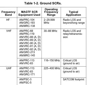
Tactical SCRs operate in the three military radio frequency bands shown in table 1-2.
Table 1-1. Frequency Range Characteristics.
Band
Ground Wave Range
Sky Wave Range
Power Required
HF 0–50 miles 100–8000 miles .5–5 kW
VHF 0–30 miles 50–150 miles .5 or less kW
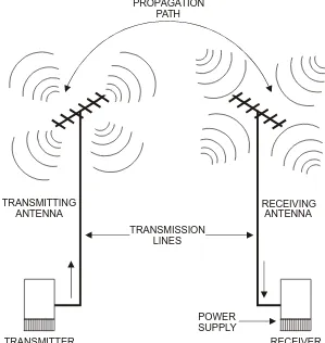
RADIO COMMUNICATION CIRCUIT
The radio equipment for communicating between two stations, including the path the radio signal follows through the air, is a radio link. A radio link consists ofsevencomponents: transmitter, power supply, transmission lines, transmitting antenna, propagation path, receiving antenna, and receiver.
Table 1-2. Ground SCRs.
Frequency Band MAGTF SCR Equipment Used Operating Frequency Range Typical Application HF AN/PRC-104 AN/GRC-193 AN/MRC-138 2–29.999 MHz
Radio LOS and beyond/long range
VHF AN/PRC-68 AN/PRC-119 AN/VRC-88 (A, D) AN/VRC-89 (A, D) AN/VRC-90 (A, D) AN/VRC-91 (A, D) AN/VRC-92 (A, D) AN/GRC-213 AN/MRC-145
30–88 MHz Radio LOS and relay/retransmis-sion
AN/PRC-113 AN/VRC-83
116–150 MHz Critical LOS (ground to air)
UHF AN/PRC-113 AN/VRC-83 AN/GRC-171
225–400 MHz Critical LOS (ground to air)
AN/PSC-3 AN/PSC-5
The transmitter generates a radio signal. The power supply provides power for the operating voltage of the radio (battery or generator). The transmission line delivers the signal from the transmitter to the transmitting antenna. The transmitting antenna sends the radio signal into space toward the receiving antenna. The path in space that the radio signal follows as it goes to the receiving antenna is the propagation path. The receiving antenna intercepts or receives the signal and sends it through a transmission line to the receiver. The receiver processes the radio signal so it can be heard (fig 1-3).
The radio operator’s objective is to provide the strongest possible signal to the receiving station. The best possible signal is one that provides the greatest signal-to-noise (S/N) ratio at the receiving antenna.
To implement a radio communications circuit it is necessary to—
• Generate and radiate an electromagnetic wave modulated with information (e.g., voice, Morse code).
• Make the wave propagate efficiently from the transmitting antenna to the receiving antenna.
• Intercept the wave by using areceiving antenna.
• Demodulate the energy so that the information originally trans-mitted becomes available in a useful form.
TRANSMISSION LINES
TRANSMITTING ANTENNA
PROPAGATION PATH
RECEIVING ANTENNA
POWER SUPPLY
TRANSMITTER RECEIVER
PROPAGATION FUNDAMENTALS
Earth’s Atmosphere
Propagation usually takes place within the Earth’s atmosphere. The atmosphere surrounding the Earth is divided into several layers, each possessing unique characteristics. The first layer, starting at the Earth’s surface and extending to a height of about 10 kilometers (km), is the troposphere. In this layer, the air temperature decreases with altitude at the rate of about 2.5°C every 300 meters.
The second layer of the atmosphere is the stratosphere, which occu-pies an altitude range extending from about 10 km to 50 km. This layer of air remains at a nearly constant temperature of about -65°C.
Beginning at about 50 km and extending upward to more than 500 km is the ionosphere. The ionosphere gets its name because the molecules of its atmosphere are ionized, i.e., electrons have been stripped away from atoms by the constant bombardment of the Sun’s rays and other high energy particles released by the Sun. Because of the large quantities of free electrons, the ionosphere is capable of interacting strongly on radio waves traveling through it.
Radio Wave Propagation
Ground Wave Propagation. Radio communications using ground wave propagation do not use or depend on waves refracted from the ionosphere (sky waves). Ground wave propagation is affected by the Earth’s electrical characteristics and by the amount of diffrac-tion (bending) of the waves along the Earth’s curvature. The ground wave’s strength at the receiver depends on the transmitter’s power output and frequency, the Earth’s shape and conductivity along the transmission path, and the local weather conditions. The ground wave includes three components: the direct wave, the ground reflected wave, and the surface wave (fig. 1-4).
Figure 1-4. Ground Wave.
Direct Wave. The direct wave travels directly from the transmitting antenna to the receiving antenna. The direct wave is limited to the LOS distance between the transmitting antenna and the receiving antenna plus the short distance added by atmospheric refraction and diffraction of the wave around the Earth’s curvature. This distance can be extended by increasing the transmitting or the receiving antenna height, or both.
GROUND REFLECTED DIRECT WAVE
SURFACE WAVE
Ground Reflected Wave. The ground reflected wave reaches the receiving antenna after being reflected from the Earth’s surface. Cancellation of the radio signal can occur when the ground reflected component and the direct wave component arrive at the receiving antenna at the same time and are 180° out of phase with each other.
Surface Wave. The surface wave follows the Earth’s curvature. It is affected by the Earth’s conductivity and dielectric constant.
Frequency Characteristics Of Ground Waves. Various frequen-cies determine which wave component will prevail along any given signal path. For example, when the Earth’s conductivity is high and the frequency of a radiated signal is low, the surface wave is the predominant component. For frequencies below 10 MHz, the sur-face wave is sometimes the predominant component. However, above 10 MHz, the losses that are sustained by the surface wave component are so great that the other components (direct wave and sky wave) become predominant.
At frequencies of 30 to 300 kHz, ground losses are very small, so the surface wave component follows the Earth’s curvature. It can be used for long-distance communications provided the radio operator has enough power from the transmitter. The frequencies 300 kHz to 3 MHz are used for long-distance communications over sea water and for medium-distance communications over land.
Earth’s Surface Conductivity. The dielectric constant or Earth’s surface conductivity determines how much of the surface wave signal energy will be absorbed or lost. Although the Earth’s surface conductivity as a whole is generally poor, the conductivity of vary-ing surface conditions, when compared one with an other, would be as stated in table 1-3.
Sky Wave Propagation.Radio communications that use sky wave propagation depend on the ionosphere to provide the signal path between the transmitting and receiving antennas.
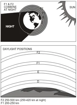
Ionospheric Structure. The ionosphere has four distinct layers. In the order of increasing heights and decreasing molecular densities, these layers are D, E, F1, and F2. During the day, when the rays of the Sun are directed toward that portion of the atmosphere, all four layers may be present. At night, the F1 and F2 layers seem to merge into a single F layer, and the D and E layers fade out. The actual number of layers, their height above the Earth, and their relative intensity of ionization vary constantly.
Table 1-3. Surface Conductivity.
Surface Type Relative Conductivity
Large body fresh water Very good
Ocean or sea water Good
Flat or hilly loamy soil Fair
Rocky terrain Poor
Desert Poor
The D layer exists only during the day and has little effect in bend-ing the paths of HF radio waves. The main effect of the D layer is to attenuate HF waves when the transmission path is in sunlit regions.
The E layer is used during the day for HF radio transmission over intermediate distances (less than 2,400 km/1,500 miles [mi]). At night the intensity of the E layer decreases, and it becomes useless for radio transmission.
The F layer exists at heights up to 380 km/240 mi above the Earth and is ionized all the time. It has two well-defined layers (F1 and F2) during the day, and one layer (F) at night. At night the F layer remains at a height of about 260 km/170 mi and is useful for long-range radio communications (over 2,400 km/1,500 mi). The F2 layer is the most useful for long-range radio communications, even though its degree of ionization varies appreciably from day to day (fig. 1-5).
The Earth’s rotation around the Sun and changes in the Sun’s activ-ity contribute to ionospheric variations. There are two main classes of these variations: regular (predictable) and irregular, occuring from abnormal behavior of the Sun.
Regular Ionospheric Variations. The four regular variations are—
• Daily: caused by the rotation of the Earth.
• Seasonal: caused by the north and south progression of the Sun. • 27-day: caused by the rotation of the Sun on its axis.
F1 & F2
F1 E
D F2 COMBINE
F2 250-500 km (250-420 km at night) F1 200-250 km
E 90-130 km D 75-90 km
SUN AT NIGHT
F2
F1
E
D DAYLIGHT POSITIONS
Irregular Ionospheric Variations. In planning a communications system, the current status of the four regular variations must be anticipated. There are also unpredictable irregular variations that must be considered. They have a degrading effect (at times blank-ing out communications) which cannot be controlled or compen-sated for at the present time. Some irregular variations are—
• Sporadic E. When excessively ionized, the E layer often blanks out the reflections from the higher layers. It can also cause unexpected propagation of signals hundreds of miles beyond the normal range. This effect can occur at any time.
• Sudden ionospheric disturbance (SID). A sudden ionospheric disturbance coincides with a bright solar eruption and causes abnormal ionization of the D layer. This effect causes total absorption of all frequencies above approximately 1 MHz. It can occur without warning during daylight hours and can last from a few minutes to several hours. When it occurs, receivers seem to go dead.
• Ionospheric storms. During these storms, sky wave reception above approximately 1.5 MHz shows low intensity and is subject to a type of rapid blasting and fading called flutter fad-ing. These storms may last from several hours to days and usu-ally extend over the entire Earth.
Frequency Characteristics in the Ionosphere.The range of long-distance radio transmission is determined primarily by the ioniza-tion density of each layer. The higher the frequency, the greater the ionization density required to reflect radio waves back to Earth. The upper (E and F) layers reflect the higher frequencies because they are the most highly ionized. The D layer, which is the least ionized, does not reflect frequencies above approximately 500 kHz. Thus, at any given time and for each ionized layer, there is an upper fre-quency limit at which radio waves sent vertically upward are reflected back to Earth. This limit is called the critical frequency.
Radio waves directed vertically at frequencies higher than the criti-cal frequency pass through the ionized layer out into space. All radio waves directed vertically into the ionosphere at frequencies lower than the critical frequency are reflected back to Earth. Radio waves used in communications are generally directed towards the iono-sphere at some oblique angle, called the angle of incidence. Radio waves at frequencies above the critical frequency will be reflected back to Earth if transmitted at angles of incidence smaller than a cer-tain angle, called the critical angle. At the critical angle, and at all angles larger than the critical angle, the radio waves pass through the ionosphere if the frequency is higher than the critical frequency. As the angle of transmission decreases, an angle is reached at which the radio waves are reflected back to Earth.
Transmission Paths.Sky wave propagation refers to those types of radio transmissions that depend on the ionosphere to provide sig-nal paths between transmitters and receivers.
ionosphere’s height and density. The antenna’s height, in relation to the operating frequency, affects the angle that transmitted radio waves strike and penetrate the ionosphere and then return to Earth. This angle of incidence can be controlled to obtain the desired cov-erage area. Lowering the antenna height increases the angle of trans-mission and provides broad and even signal patterns in a large area.
Using near-vertical transmission paths is known as near-vertical incidence sky wave (NVIS). Raising the antenna height lowers the angle of incidence. Lowering the angle of incidence produces a skip zone in which no usable signal is received. This area is bounded by the outer edge of usable ground wave propagation and the point nearest the antenna at which the sky wave returns to Earth. In short-range communications situations, the skip zone is an undesirable condition. However, low angles of incidence make long-distance communications possible.
When a transmitted wave is reflected back to the Earth’s surface, the Earth absorbs part of the energy. The remaining energy is reflected back into the ionosphere to be reflected back again. This means of transmission—alternately reflecting the radio wave between the ionosphere and the Earth—is called hops. Hops enable radio waves to be received at great distances from the point of origin.
reliability. Only when the signal level fades down below the back-ground noise level for an appreciable fraction of time will increased transmitter power or antenna gain yield an overall circuit improve-ment. Choosing the correct frequency and using transmitting and receiving equipment intelligently ensure a strong and reliable receiving signal, even when low power is used.
Maximum Usable and Lowest Usable Frequencies. Using a given ionized layer and a transmitting antenna with a fixed angle of radiation, there is a maximum frequency at which a radio wave will return to Earth at a given distance. This frequency is called the max-imum usable frequency (MUF). It is the monthly median of the daily highest frequency that is predicted for sky wave transmission over a particular path at a particular hour of the day. The MUF is always higher than the critical frequency because the angle of inci-dence is less than 90°. If the distance between the transmitter and the receiver is increased, the MUF will also increase. Radio waves lose some of their energy through absorption by the D layer and a portion of the E layer at certain transmission frequencies.
Propagation Prediction.Although a detailed discussion of propa-gation prediction methods is beyond the scope of this publication, it should be noted that propagation predictions can be obtained from a system planning, engineering, and evaluation device (SPEED).
Other Factors Affecting Propagation
In the VHF and UHF ranges, extending from 30 to 300 MHz and beyond, the presence of objects (e.g., buildings or towers) may pro-duce strong reflections that arrive at the receiving antenna in such a way that they cancel the signal from the desired propagation path and render communications impossible. Most Marines are familiar with distant TV station reception interference caused by high-flying aircraft. The signal bouncing off of the aircraft alternately cancels and reinforces the direct signal from the TV station as the aircraft changes position relative to the transmitting and receiving antennas.
This same interference can adversely affect the ordinary voice com-munications circuit at VHF and UHF, rendering the received signal unintelligible for brief periods of time. Receiver locations that avoid the proximity of an airfield should be chosen if possible. Avoid locating transmitters and receivers where an airfield is at or near midpoint of the propagation path of frequencies above 20 MHz.
Path Loss
Radio waves become weaker as they spread from the transmitter. The ratio of received power to transmitted power is called path loss. LOS paths at VHF and UHF require relatively little power since the total path loss at the radio horizon is only about 25 decibels (dB) greater than the path loss over the same distance in free space (absence of ground). This additional loss results from some energy being reflected from the ground, canceling part of the direct wave energy. This is unavoidable in almost every practical case. The total path loss for an LOS path above average terrain varies with the fol-lowing factors: total path loss between transmitting and receiving antenna terminals, frequency, distance, transmitting antenna gain, and receiving antenna gain.
Reflected Waves
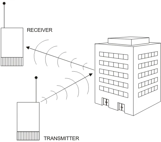
Often, it is possible to communicate beyond the normal LOS dis-tance by exploiting the reflection from a tall building, nearby moun-tain, or water tower (fig. 1-6 on page 1-20). If the top portion of a structure or hill can be seen readily by both transmitting and receiv-ing antennas, it may be possible to achieve practical communica-tions by directing both antennas toward the point of maximum reflection. If the reflecting object is very large in terms of a wave-length, the path loss, including the reflection, can be very low.
two conditions represent destructive and constructive combinations of the reflected and direct waves.
Reflection from the ground at the common midpoint between the receiving and transmitting antennas may also arrive in a construc-tive or destrucconstruc-tive manner. Generally, in the VHF and UHF range, the reflected wave is out of phase (destructive) with respect to the direct wave at vertical angles less than a few degrees above the horizon. However, since the ground is not a perfect conductor, the amplitude of the reflected wave seldom approaches that of the direct wave. Thus, even though the two arrive out of phase, com-plete cancellation does not occur. Some improvement may result from using vertical polarization rather than horizontal polarization
TRANSMITTER RECEIVER
over LOS paths because there tends to be less phase difference between direct and reflected waves. The difference is usually less than 10 dB, however, in favor of vertical polarization.
Diffraction
Unlike the ship passing beyond the visual horizon, a radio wave does not fade out completely when it reaches the radio horizon. A small amount of radio energy travels beyond the radio horizon by a process called diffraction. Diffraction also occurs when a light source is held near an opaque object, casting a shadow on a surface behind it. Near the edge of the shadow a narrow band can be seen which is neither completely light nor dark. The transition from total light to total darkness does not occur abruptly, but changes smoothly as the light is diffracted.
A radio wave passing over either the curved surface of the Earth or a mountain ridge behaves in much the same fashion as a light wave. For example, people living in a valley below a high, sharp, moun-tain ridge can often receive a TV station located many miles below on the other side. Figure 1-7 illustrates how radio waves from the
TV station are diffracted by the mountain ridge and bent downward in the direction of the village. It is emphasized, however, that the energy decays very rapidly as the angle of propagation departs from the straight LOS path. Typically, a diffracted signal may undergo a reduction of 30 to 40 dB by being bent only 5 feet by a mountain ridge. The actual amount of diffracted signal depends on the shape of the surface, the frequency, the diffraction angle, and many other factors. It is sufficient to say that there are times when the use of diffraction becomes practical as a means for communicating in the VHF and UHF over long distances.
Tropospheric Refraction, Ducting, and Scattering
Refraction is the bending of a wave as it passes through air layers of different density (refractive index). In semitropical regions, a layer of air 5 to 100 meters thick with distinctive characteristics may form close to the ground, usually the result of a temperature inver-sion. For example, on an unusually warm day after a rainy spell, the Sun may heat up the ground and create a layer of warm, moist air. After sunset, the air a few meters above the ground will cool very rapidly while the moisture in the air close to the ground serves as a blanket for the remaining heat. After a few hours, a sizable differ-ence in temperature may exist between the air near the ground and the air at a height of 10 to 20 meters, resulting in a marked differ-ence in air pressure. Thus, the air near the ground is considerably denser than the air higher up. This condition may exist over an area of several hundred square kilometers or over a long area of land near a seacoast. When such an air mass forms, it usually remains stable until dawn, when the ground begins to cool and the tempera-ture inversion ends.
antenna and a distant receiving site. The effects of such ducting can be seen frequently during the year in certain locations where TV or VHF FM stations are received over paths of several hundred kilo-meters. The total path loss within such a duct is usually very low and may exceed the free space loss by only a few dBs.
It is also possible to communicate over long distances by means of tropospheric scatter. At altitudes of a few kilometers, the air mass has varying temperature, pressure, and moisture content. Small fluctuations in tropospheric characteristics at high altitude create
blobs. Within a blob, the temperature, pressure, and humidity are different from the surrounding air. If the difference is large enough, it may modify the refractive index at VHF and UHF. A random dis-tribution of these blobs exists at various altitudes at all times. If a high-power transmitter (greater than 1 kW) and high gain antenna (10 dB or more) are used, sufficient energy may be scattered from these blobs down to the receiver to make reliable communication possible over several hundred kilometers. Communication circuits employing this mode of propagation must use very sensitive receiv-ers and some form of divreceiv-ersity to reduce the effects of the rapid and deep fading. Scatter propagation is usually limited to path distances of less than about 500 km.
NOISE
Natural Noise
Natural noise has two principle sources: thunderstorms (atmo-spheric noise) and stars (galactic noise). Both sources generate sharp pulses of electromagnetic energy over all frequencies. The pulses propagate according to the same laws as manmade signals, and receiving systems must accept them along with the desired sig-nal. Atmospheric noise is dominant from 0 to 5 MHz, and galactic noise is most important at all higher frequencies. Low frequency transmitters must generate very strong signals to overcome noise. Strong signals and strong noise mean that the receiving antenna does not have to be large to collect a usable signal (a few hundred microvolts). A 1.5 meter tuned whip will deliver adequately all of the signals that can be received at frequencies below 1 MHz.
Manmade Noise
Manmade noise is a product of urban civilization that appears wher-ever electric power is used. It is generated almost anywhere that there is an electric arc (e.g., automobile ignition systems, power lines, motors, arc welders, fluorescent lights). Each source is small, but there are so many that together they can completely hide a weak signal that would be above the natural noise in rural areas. Man-made noise is troublesome when the receiving antenna is near the source, but being near the source gives the noise waves characteris-tics that can be exploited. Waves near a source tend to be vertically polarized. A horizontally polarized receiving antenna will generally receive less noise than a vertically polarized antenna.
with respect to the receiver input terminals (zero voltage across ter-minals), and this noise will not be received. Near-perfect balance is difficult to achieve, but any balance helps.
Other ways to avoid manmade noise are to locate the most trouble-some sources and turn them off, or move the receiving system away from them. Moving a kilometer away from a busy street or highway will significantly reduce noise. Although broadband receiving antennas are convenient because they do not have to be tuned to each working frequency, sometimes a narrowband antenna can make the difference between communicating and not communicat-ing. The HF band is now so crowded with users that interference and noise, not signal strength, are the main reasons for poor com-munications. A narrowband antenna will reject strong interfering signals near the desired frequency and help maintain good commu-nications.
Antenna Fundamentals
All radios, whether transmitting or receiving, require some sort of antenna. The antenna accepts power from the transmitter and launches it into space as an electromagnetic or radio wave. At the receiving end of the circuit, a similar antenna collects energy from the passing electromagnetic wave and converts it into an alternating electric current or signal that the receiver can detect.
How well antennas launch and collect electromagnetic waves directly influences communications reliability and quality. The function of an antenna depends on whether it is transmitting or receiving.
Section I. Concepts and Terms
To select the right antennas for a radio circuit, certain concepts and terms must be understood. This section defines several basic terms and relationships which will help the reader understand antenna fundamentals. These include: forming a radio wave, radiation fields and patterns, polarization, directionality, resonance, reception, reci-procity, impedance, bandwidth, gain, and take-off angle.
FORMING A RADIO WAVE
When an alternating electric current flows through a conductor (wire), electric and magnetic fields are created around the conduc-tor. If the length of the conductor is very short compared to a wave-length, the electric and magnetic fields will generally die out within a distance of one or two wavelengths. However, as the conductor is lengthened, the intensity of the fields enlarge. Thus, an ever-increasing amount of energy escapes into space. When the length of the wire approaches one-half of a wavelength at the frequency of the applied alternating current, most of the energy will escape in the form of electromagnetic radiation. For effective communications to occur, the following must exist: alternating electric energy in the form of a transmitter, a conductor or a wire, an electric current flowing through the wire, and the generation of both electric and magnetic fields in the space surrounding the wire.
RADIATION
upward on the wire to the top, where they have no place to go and are bounced back toward the lower end. As the electrons reach the lower end in phase, i.e., in step with the radio energy then being applied by the transmitter, the energy of their motion is strongly reinforced as they bounce back upward along the wire. This regen-erative process sustains the oscillation. The wire is resonant at the frequency at which the source of energy is alternating.
The radio power supplied to a simple wire antenna appears nearly equally distributed throughout its length. The energy stored at any location along the wire is equal to the product of the voltage and the current at that point. If the voltage is high at a given point, the cur-rent must be low. If the curcur-rent is high, the voltage must be low. The electric current is maximum near the bottom end of the wire.
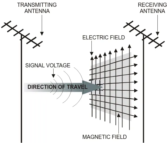
Radiation Fields
When RF power is delivered to an antenna, two fields evolve. One is an induction field, which is associated with the stored energy; the other is a radiation field. At the antenna, the intensities of these fields are large and are proportional to the amount of RF power delivered to the antenna. At a short distance from the antenna and beyond, only the radiation field remains. This field is composed of an electric component and a magnetic component (see fig. 2-1 on page 2-4).
Figure 2-1. Radiation Fields.
Radiation Patterns
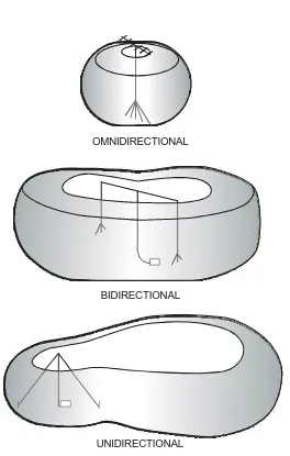
The radio signals radiated by an antenna form an electromagnetic field with a definite pattern, depending on the type of antenna used. This radiation pattern shows the antenna’s directional characteris-tics. A vertical antenna radiates energy equally in all directions (omnidirectional), a horizontal antenna is mainly bidirectional, and a unidirectional antenna radiates energy in one direction. However, the patterns are usually distorted by nearby obstructions or terrain features. The full- or solid-radiation pattern is represented as a three-dimensional figure that looks somewhat like a doughnut with a transmitting antenna in the center (fig 2-2).
TRANSMITTING ANTENNA
RECEIVING ANTENNA
ELECTRIC FIELD
SIGNAL VOLTAGE
.
Figure 2-2. Radiation Patterns. OMNIDIRECTIONAL
BIDIRECTIONAL
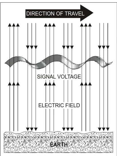
POLARIZATION
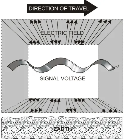
A radiated wave’s polarization is determined by the direction of the lines of force making up the electric field. If the lines of electric force are at right angles to the Earth’s surface, the wave is vertically polarized (fig. 2-3). If the lines of electric force are parallel to the Earth’s surface, the wave is horizontally polarized (fig. 2-4). When a single-wire antenna extracts (receives) energy from a passing
EARTH
SIGNAL VOLTAGE
ELECTRIC FIELD
DIRECTION OF TRAVEL
radio wave, maximum pickup results if the antenna is oriented in the same direction as the electric field component. A vertical antenna receives vertically polarized waves, and a horizontal antenna receives horizontally polarized waves. If the field rotates as the waves travel through space, both horizontal and vertical com-ponents of the field exist, and the wave is elliptically polarized.
.
Figure 2-4. Horizontal Polarization.
EARTH
SIGNAL VOLTAGE ELECTRIC FIELD
Polarization Requirements for Various Frequencies
At medium and low frequencies, ground wave transmission is used extensively, and it is necessary to use vertical polarization. Vertical lines of force are perpendicular to the ground, and the radio wave can travel a considerable distance along the ground surface with a minimum amount of loss. Because the Earth acts as a relatively good conductor at low frequencies, horizontal lines of electric force are shorted out, and the useful range with the horizontal polariza-tion is limited.
At high frequencies, with sky wave transmission, it makes little dif-ference whether horizontal or vertical polarization is used. The sky wave, after being reflected by the ionosphere, arrives at the receiv-ing antenna elliptically polarized. Therefore, the transmittreceiv-ing and receiving antennas can be mounted either horizontally or vertically. Horizontal antennas are preferred, since they can be made to radiate effectively at high angles and have inherent directional properties.
For frequencies in the VHF or UHF range, either horizontal or ver-tical polarization is satisfactory. Since the radio wave travels directly from the transmitting antenna to the receiving antenna, the original polarization produced at the transmitting antenna is main-tained as the wave travels to the receiving antenna. If a horizontal antenna is used for transmitting, a horizontal antenna must be used for receiving.
Advantages of Vertical Polarization
Simple vertical half-wave and quarter-wave antennas provide omnidirectional communications. This is desirable in communicat-ing with a movcommunicat-ing vehicle. The disadvantage is that it radiates equally to the enemy and friendly forces.
When antenna heights are limited to 3.05 meters (10 feet) or less over land, as in a vehicular installation, vertical polarization pro-vides a stronger received signal at frequencies up to about 50 MHz. From about 50 to 100 MHz, there is only a slight improvement over horizontal polarization with antennas at the same height. Above 100 MHz, the difference in signal strength between vertical and hori-zontal polarization is small. However, when antennas are located near dense forests, horizontally polarized waves suffer lower losses than vertically polarized waves.
Vertically polarized radiation is somewhat less affected by reflec-tions from aircraft flying over the transmission path. With horizon-tal polarization, such reflections cause variations in received signal
DIRECTION OF TRAVEL
DIRECTION OF ROTATION, RIGHT-HAND
strength. An example is the picture flutter in a television set when an aircraft interferes with the transmission path. This factor is important in areas where aircraft traffic is heavy.
When vertical polarization is used, less interference is produced or picked up from strong VHF and UHF transmissions (TV and FM broadcasts) because they use horizontal polarization. This factor is important when an antenna must be located in an urban area that has TV or FM broadcast stations.
Advantages of Horizontal Polarization
A simple horizontal half-wave antenna is bidirectional. This charac-teristic is useful in minimizing interference from certain directions.
Horizontal antennas are less likely to pick up manmade interfer-ence, which is ordinarily vertically polarized. When antennas are located near dense forests, horizontally polarized waves suffer lower losses than vertically polarized waves, especially above 100 MHz. Small changes in antenna location do not cause large varia-tions in the field intensity of horizontally polarized waves when an antenna is located among trees or buildings. When vertical polariza-tion is used, a change of only a few feet in the antenna locapolariza-tion may have a significant effect on the received signal strength.
DIRECTIONALITY
impossible. However, reception of a desired signal can be improved by using directional antennas.
Horizontal half-wave antennas accept radio signals from all direc-tions. The strongest reception is received in a line perpendicular to the antenna (i.e., broadside, and the weakest reception is received from the direction of the ends of the antenna). Interfering signals can be eliminated or reduced by changing the antenna installation so that either end of the antenna points directly at the interfering station.
Communications over a radio circuit is satisfactory when the received signal is strong enough to override undesired signals and noise. The receiver must be within range of the transmitter. Increas-ing the transmittIncreas-ing power between two radio stations increases communications effectiveness. Also, changing the types of trans-mission, changing to a frequency that is not readily absorbed, or using a directional antenna aids in communications effectiveness.
Directional transmitting antennas concentrate radiation in a given direction and minimize radiation in other directions. A directional antenna may also be used to lessen interception by the enemy and interference with friendly stations.
RESONANCE
frequency). If a resonant antenna is used for a radio circuit, a sepa-rate antenna must be built for each frequency to be used on the radio circuit. A nonresonant antenna, on the other hand, will effec-tively radiate a broad range of frequencies with less efficiency. Res-onant and nonresRes-onant antennas are commonly used on tactical circuits. Resonance can be achieved in two ways: physically ing the length of the antenna to the wave and electronically match-ing the length of the antenna to the wave.
RECEPTION
The radio waves that leave the transmitting antenna will have an influence on and will be influenced by any electrons in their path. For example, as an HF wave enters the ionosphere, it is reflected or refracted back to earth by the action of free electrons in this region of the atmosphere. When the radio wave encounters the wire or metallic conductors of the receiving antenna, the radio wave’s elec-tric field will cause the electrons in the antenna to oscillate back and forth in step with the wave as it passes. The movement of these electrons within the antenna is the small alternating electrical cur-rent which is detected by the radio receiver.
If an antenna is located within a congested urban environment or within a building, there are many objects which will scatter or re-raditate the energy in a manner that can be detrimental to reception. For example, the electric wiring inside a building can strongly re-radiate RF energy. If a receiving antenna is in close proximity to wires, it is possible for the reflected energy to cancel the energy received directly from the desired signal path. When this condition exists, the receiving antenna should be moved to another location within the room where the reflected and direct signals may rein-force rather than cancel each other.
RECIPROCITY
The various properties of an antenna apply equally, regardless of whether the antenna is used for transmitting or receiving. This is what is meant by reciprocity of antennas. For example, the more efficient a certain antenna is for transmitting, the more efficient it will be for receiving the same frequency. The directive properties of a given antenna will be the same whether it is used for transmis-sion or reception.
IMPEDANCE
Impedance is the relationship between voltage and current at any point in an alternating current circuit. The impedance of an antenna is equal to the ratio of the voltage to the current at the point on the antenna where the feed is connected (feed point). If the feed point is located at a point of maximum current, the antenna impedance is 20 to 100 ohms. If the feed point is moved to a maximum voltage point, the impedance is as much as 500 to 10,000 ohms.
The input impedance of an antenna depends on the conductivity or impedance of the ground. For example, if the ground is a simple stake driven about a meter into earth of average conductivity, the impedance of the monopole may be double or even triple the quoted values. Because this additional resistance occurs at a point on the antenna circuit where the current is high, a large amount of
MAXIMUM RADIATION MAXIMUM RECEPTION
TRANSMITTING ANTENNA
RECEIVING ANTENNA
transmitter power will dissipate as heat into the ground rather than radiated as intended. Therefore, it is essential to provide as good a ground or artificial ground (counterpoise) connection as possible when using a vertical whip or monopole.
The amount of power an antenna radiates depends on the amount of current which flows in it. Maximum power is radiated when there is maximum current flowing. Maximum current flows when the impedance is minimized—when the antenna is resonated so that its impedance is pure resistance. (When capacitive reactance is made equal to inductive reactance, they cancel each other, and impedance equals pure resistance.)
BANDWIDTH
The bandwidth of an antenna is that frequency range over which it will perform within certain specified limits. These limits are with respect to impedance match, gain, and/or radiation pattern charac-teristics. Typical specification limits are—
• An impedance mismatch of less than 2:1 relative to some stan-dard impedance such as 50 ohms.
• A loss in gain or efficiency of no more than 3 dB.
• A directivity pattern whose main beam is 13 dB greater than any of the side lobes, and a back lobe at least 15 dB below the main beam.
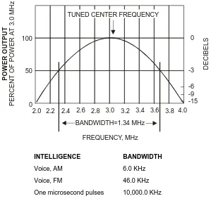
In the radio communication process, intelligence changes from speech or writing into a low frequency signal that is used to modu-late, or cause change, in a much higher frequency radio signal. When transmitted by an antenna, these radio signals carry the intel-ligence to the receiving antenna, where it is picked up and recon-verted into the original speech or writing. There are natural laws which limit the amount of intelligence or signal that can be trans-mitted and received at a given time. The more words per minute, the higher the rate and the modulation frequency, so a wider or greater bandwidth is needed. To transmit and receive all the intelli-gence necessary, the antenna bandwidth must be as wide or wider than the signal bandwidth, otherwise it will limit the signal frequen-cies, causing voices and writing to be unintelligible. Too wide a bandwidth is also bad, since it accepts extra voices and will degrade the S/N ratio. Figure 2-7 shows how signal bandwidth is defined and gives some examples of bandwidth required to transmit ordi-nary types of intelligence.
GAIN
Figure 2-7. Bandwidth. BANDWIDTH=1.34 MHz
FREQUENCY, MHz
2.0 2.2 2.4 2.6 2.8 3.0 3.2 3.4 3.6 3.8 4.0 0
50 100
TUNED CENTER FREQUENCY
-15 -6 -9 -3 0 P O W E R O U T P U T P E R C E N T O F P O W E R A T 3 .0 M H z D E C IB E L S INTELLIGENCE BANDWIDTH
Voice, AM 6.0 KHz
Voice, FM 46.0 KHz
One microsecond pulses 10,000.0 KHz
TAKE-OFF ANGLE
The antenna’s take-off angle is the angle above the horizon that an antenna radiates the largest amount of energy (see fig. 2-8). VHF communications antennas are designed so that the energy is radi-ated parallel to the Earth (do not confuse take-off angle and polar-ization). The take-off angle of an HF communications antenna can determine whether a circuit is successful or not. HF sky wave antennas are designed for specific take-off angles, depending on the circuit distance. High take-off angles are used for short-range munications, and low take-off angles are used for long-range com-munications.
Figure 2-8. Take-Off Angle.
ANTENNA
MAIN ENERGY FROM ANTENNA
Section II. Ground Effects
Since most tactical antennas are erected over the Earth and not out in free space, except for those on satellites, the ground will alter the free space radiation patterns of antennas. The ground will also affect some of the electrical characteristics of an antenna. It has the greatest effect on those antennas that must be mounted relatively close to the ground in terms of wavelength. For example, medium-and high-frequency antennas, elevated above the ground by only a fraction of a wavelength, will have radiation patterns that are quite different from the free-space patterns.
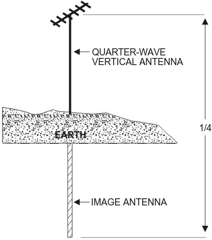
GROUNDED ANTENNA THEORY
Figure 2-9. Quarter-Wave Antenna Connected to Ground.
TYPES OF GROUNDS
When grounded antennas are used, it is especially important that the ground has as high a conductivity as possible. This reduces ground losses and provides the best possible reflecting surface for the down-going radiated energy from the antenna. At low and medium frequencies, the ground acts as a good conductor. The ground con-nection must be made in such a way as to introduce the least possi-ble amount of resistance to ground. At higher frequencies, artificial grounds constructed of large metal surfaces are common.
1/4 QUARTER-WAVE
VERTICAL ANTENNA
IMAGE ANTENNA
The ground connections take many forms, depending on the type of installation and the loss that can be tolerated. In many simple field installations, the ground connection is made by one or more metal rods driven into the soil. Where more satisfactory arrangements cannot be made, ground leads can be connected to existing devices which are grounded. Metal structures or underground pipe systems are commonly used as ground connections. In an emergency, a ground connection can be made by forcing one or more bayonets into the soil.
When an antenna must be erected over soil with low conductivity, treat the soil to reduce resistance. Treat the soil with substances that are highly conductive when in solution. Some of these substances, listed in order of preference, are sodium chloride (common salt), calcium chloride, copper sulfate (blue vitriol), magnesium sulfate (Epsom salt), and potassium nitrate (saltpeter). The amount required depends on the type of soil and its moisture content.
WARNING
WHEN THESE SUBSTANCES ARE USED, IT IS IMPORTANT THAT THEY DO NOT GET INTO NEARBY DRINKING WATER SUPPLIES.
Counterpoise
When an actual ground connection cannot be used because of the high resistance of the soil or because a large buried ground system is not practical, a counterpoise may be used to replace the usual direct ground connection. The counterpoise (fig. 2-10) consists of a device made of wire, which is erected a short distance above the ground and insulated from it. The size of the counterpoise should be at least equal to or larger than the size of the antenna.
When the antenna is mounted vertically, the counterpoise should be made into a simple geometric pattern. Perfect symmetry is not required. The counterpoise appears to the antenna as an artificial ground that helps to produce the required radiation pattern.
Figure 2-10. Wire Counterpoise.
ANTENNA COUNTERPOISE
In some VHF antenna installations on vehicles, the metal roof of the vehicle (or shelter) is used as a counterpoise for the antenna. Small counterpoises of metal mesh are sometimes used with special VHF antennas that must be located a considerable distance above the ground.
Ground Screen
Section III. Calculating Antenna Length
An antenna’s length must be considered in two ways: physical and electrical. The two are never the same. The reduced velocity of the wave on the antenna and a capacitive effect (end effect) make the antenna seem longer electrically than physically. The contributing factors are the ratio of the diameter of the antenna to its length and the capacitive effect of terminal equipment (e.g., insulators or clamps) used to support the antenna.
To calculate the antenna’s physical length, use a correction of 0.95 for frequencies between 3 and 50 MHz. The figures given are for a half-wave antenna.
The length of a long-wire antenna (one wavelength or longer) for harmonic operation is calculated by using the following formula, where N = number of half-wavelengths in the total length of the antenna.
Length (meters) = 150 x 0.95 = 142.50 Frequency in MHz Frequency in MHz
Length (feet) = 492 x 0.95 = 468 Frequency in MHz Frequency in MHz
Length (meters) = 150 (N - 0.05) Frequency in MHz
Example: 3 half-wavelengths at 7 MHz is—
Length (meters) = 150 (N - 0.05) Frequency in MHz
= 150 (3 - .05) 7
= 150 x 2.95 7
= 442.50 7
Section IV. Antenna Orientation
The orientation of an antenna is extremely important. Determining the position of an antenna in relation to the points of the compass can make the difference between a marginal and good radio circuit.
AZIMUTH
If the azimuth of the radio’s path is not provided, determine it by the best available means. The accuracy required depends on the radia-tion pattern of the direcradia-tional antenna. If the antenna beamwidth is very wide (e.g., 90° angle between half-power points) an error of
90° 90°
270°
270° 0° 0°
180° 180°
HALF-POWER POINTS
RELATIVE POWER RELATIVE
FIELD STRENGTH
10° is of little consequence. In transportable operation, the rhombic and vee antennas may have such a narrow beam that great accuracy is required to determine azimuth. The antenna should be erected for the correct azimuth. Great accuracy is not required to erect broad-beam antennas.
Unless a line of known azimuth is available at the site, the direction of the path is best determined by a magnetic compass. Figure 2-12 on page 2-28 is a map of magnetic declination, showing the varia-tion of the compass needle from the true north. When the compass is held so that the needle points to the direction indicated for the location on the map, all directions indicated by the compass will be true.
Improvement of Marginal Communications
It may not always be feasible to orient directional antennas to the correct azimuth of the desired radio path, and marginal communica-tions may suffer. To improve marginal communicacommunica-tions—
• Check, tighten, and tape cable couplings and connections. • Retune all transmitters and receivers in the circuit.
• Check that the antennas are adjusted for proper operating fre-quency.
• Change the heights of antennas.
• Move the antenna a short distance away and in different loca-tions from its original location.
8 0 7 0 6 0 5 0 4 0 3 0 2 0 1 0 0 1 0 2 0 3 0 4 0 5 0 6 0 7 0 8 0 8 0 7 0 6 0 5 0 4 0 3 0 2 0 1 0
0 10 20 30 04 50 60 70 80
1 8 0 1 8 0 1 8 0 1 8 0 1 6 0 1 6 0 1 6 0 1 6 0 1 4 0 1 4 0 1 4 0 1 4 0 1 2 0 1 2 0 1 2 0 1 2 0 1 0 0 1 0 0 1 0 0 1 0 0 8 0 8 0 8 0 8 0 6 0 6 0 6 0 6 0 4 0 4 0 4 0 4 0 2 0 2 0 2 0 2 0 0 0 6 0 E 6 0 W 6 0 W 5 5 W 5 0 W 4 5 W 4 0 W 3 5 W 3 0 W 2 5 W 2 0 W 1 5 W 1 0 W 5 W 0 E 5 E 1 0 E 2 0 E 2 5 E 4 0 E 5 5
W 45W
5 0 W 4 0 W 3 5 W 3 0 W 2 5 W 2 0 W 1 5 W 1 0 W 5 W 0 5 E 5 0 E 4 0 E 3 5 E 3 0 E 2 5 E 2 0 E 1 5 E 1 0 E 1 0 E 1 5 E 2 0 E 2 5 E 3 0 E 3 5 E 4 0 E 5 0 E 6 0 E 3 5 E 5 W 5
W 5E
1 0 E 1 5 E 2 0 E 2 5 E 3 5 E 3 0 E 4 0 E 5 0
E 60
E 0 1 0 W 3 0 E S M P N M P
Transmission and Reception of Strong Signals
After an adequate site has been selected and the proper antenna ori-entation obtained, the signal level at the receiver will be propor-tional to the strength of the transmitted signal.
WARNING
EXCESSIVE SIGNAL STRENGTH MAY RESULT IN ENEMY IN-TERCEPT AND INTERFERENCE OR IN YOUR INTERFERENCE WITH ADJACENT FREQUENCIES.
If a high-gain antenna is used, a stronger signal can be obtained. Losses between the antenna and the equipment can be reduced by using a high quality transmission line, as short as possible, and properly matched at both ends.
WARNING
BE EXTREMELY CAREFUL WHEN PUTTING UP, TAKING DOWN, OR MOVING ANTENNAS LOCATED NEAR HIGH VOLT-AGE OR COMMECIAL POWER LINES. ANTENNA CONTACT WITH THESE CAN AND MAY RESULT IN ELECTROCUTION OR SEVERE INJURY TO PERSONNEL HOLDING THE ANTEN-NA OR THE CONNECTING GUY WIRES AND CABLES.
Transmission Lines
Transmission lines (antenna feed lines) conduct or guide electrical energy from the transmitter to the receiver. This chapter is oriented primarily toward transmission lines with field expedient antennas. For standard issue radios and antennas, use the issued coaxial cable. As long as radios, cables, and antennas are maintained in working order, they will operate as designed and won’t require any adjust-ments or changes based on the information in this chapter.
PROPERTIES
Transmission Line Types
Transmission lines are classified according to construction and length, and fall into two main categories: balanced line and unbal-anced line. The terms balunbal-anced and unbalunbal-anced describe the rela-tionship between transmission line conductors and the Earth. Transmission lines may be classified as resonant or nonresonant lines, each of which may have advantages over the other under a given set of circumstances.
are equal and opposite (i.e. at the moment one of the conductors supports a positive voltage with respect to ground, the other sup-ports a negative voltage of equal magnitude). Some balanced lines carry a third conductor in the form of a braided shield, which acts as ground. Conductor spacings up to several centimeters are com-monly used. Figure 3-1 shows balanced and unbalanced lines.
Figure 3-1. Balanced and Unbalanced Transmission Lines.
PLASTIC COVERING
INSULATORS
BRAIDED WIRE SHIELD
PLASTIC COVERING
SHIELDED LINE OPEN TWIN LINES
CONDUCTING GROUND PLANE
OPEN SINGLE WIRE LINE
PLASTIC COVERING
BRAID
SHIELDED LINE(COAX)
Unbalanced Line. The unbalanced line is usually open single-wire line or coaxial cable. It is one-half of a balanced line.
Nonresonant Line. A nonresonant line is a line that has no stand-ing waves of current and voltage. It is either infinitely long or is ter-minated in its characteristic impedance. Because there are no reflections, all of the energy passed along the line is absorbed by the load (except for the small amount of energy dissipated by the line).
Resonant Line. A resonant transmission line has standing waves of current and voltage. The line is of finite length and is not terminated in its characteristic impedance. Reflections are present. A resonant line, like a tuned circuit, is resonant at some particular frequency. The resonant line will present to its source of energy a high or a low resistive impedance at multiples of a quarter-wavelength. Whether the impedance is high or low at these points depends on whether the line is short- or open-circuited at the output end. At points that are not exact multiples of a quarter-wavelength, the line acts as a capac-itor or an inductor.
MINIMIZING ENERGY LOSS
To communicate with minimal energy loss, elements such as imped-ance matching and attenuation (line losses) must be considered.
Impedance
A radio wave consists of electric and magnetic fields arranged per-pendicularly to each other and to the direction the wave travels. The impedance associated with this wave is the ratio of the potential dif-ference (voltage) to the current (amperage) at a given point along a transmission line. The following formula illustrates this.
In transmission lines, because of the length-frequency relationship, the characteristic impedance is more often discussed in terms of capacitance and inductance. In conventional circuits that contain inductors and capacitors, the inductance and capacitance are present in definite lumps. In an RF transmission line, however, these quan-tities are distributed throughout the entire line and cannot be sepa-rated from each other.
If a transmitter is connected to a transmission line that is terminated in a load whose impedance is different from that of the line, only a portion of the available energy will be accepted by the load antenna, and the remainder will be reflected back down the line in the direc-tion of the transmitter. The energy is actually traveling in both directions along the line.
If a transmitter is connected to a transmission line terminated in a load whose impedance exactly equals the impedance of the line, the line will absorb all of the energy except for that lost in the resistive and dielectric losses of the line. Current flowing through the line will be uniformly distributed along its length, and the voltage between the conductors on the line will be equal at all points. When this condition exists, the line is said to be perfectly matched and carries only a forward or incident wave. If the impedance of the transmission line and the load also equal the internal impedance (output impedance) of the transmitter, a maximum transfer of
energy (lowest system loss) is achieved (i.e., the transmitter or receiver, transmission line, and antenna are all the same imped-ance), and the best possible transfer of signal energy will occur.
Optimizing Line Length
When it is necessary to use a transmission line whose impedance is significantly different from that of the load, it is possible to make good use of standing waves and the repetitive impedance variations along the line to match the antenna to the transmitter or the receiver to the antenna by cutting the line to a specific length. An example is when the only available equipment consists of a 300-ohm twin-lead transmission line; a 50-ohm half-wave dipole antenna; and a 50-ohm internal impedance transceiver. (Note: The internal imped-ance of most USMC radios is 50 ohms). Ordinarily, this impedimped-ance combination would result in lost energy that could affect the qual-ity of communications. However, if a single frequency is used to communicate, the length between the antenna and the receiver can be matched. This occurs because the impedance of the receiver is repeated at intervals of a half-wavelength along the line.
Attenuation
Transmission lines do not transfer all of the energy applied at one end of the line to the opposite end. Attenuation is energy that is lost when converted into heart, partially due to conductor (wire) resis-tance. More energy is lost due to the insulation material used to space the conductors (dielectric loss). Some insulating materials (e.g., Teflon) have extremely low loss while others (e.g., rubber or wood) have relatively high loss, especially at frequencies above about 30 MHz. Old, dry wood (especially redwood) may be boiled in paraffin or bee’s wax to make a fairly good insulator at frequen-cies up to about 200 MHz. Polyethylene, a common insulation material used in coaxial cables, has an average loss of about twice that of Teflon in the 100-MHz range for cables having a diameter of less than about one centimeter. Dry air is a better insulator than most solid, liquid, or flexible materials. Some inert gases (e.g., nitrogen, helium, and argon) are superior to air and are often used under pressure to fill coaxial cables used with high-powered trans-mitters.