Vol. 4, Issue 8, August 2015
Incremental Nth Best Relay Selection with
Code Based Relay Construction in Fading
Channel
KiranKrishnan1, Fathima A.2
Assistant Professor, Dept. of ECE, CAARMEL Engineering College, Pathanamthitta, Kerala, India1
PG Student, Dept. of ECE, CAARMEL Engineering College, Pathanamthitta, Kerala, India2
ABSTRACT: Transmission of data through a channel will be subjected to lot of noises and fading effects. Because of
this there will be lot of errors in received data. Taking this into consideration, in this paper, we consider incremental amplify-and-forward (AF) relaying technique which employ the Nth best relay when the best relay is unavailable due to issues such as scheduling or load balancing. We are performing the analysis on a Rayleigh fading channel. In order to overcome the effects of fading and noise, in this paper, we are also incorporating code based relay construction along with interleaving in order to detect and correct errors. According to the analysis, the incremental AF strategy can reduce BER greatly when compared to the conventional direct communication. The incremental AF strategy improves the capacity over other conventional relay selection schemes. The incremental Nth best relay can be useful when considering improving the error rate and bandwidth efficiency at the same time comparing to the conventional direct system.
KEYWORDS: Nth Best Relay, Incremental Relaying, Amplify-and-Forward, Fading Channels.
I. INTRODUCTION
The relay nodes help in communication between source node and destination node by forwarding the received information from the source node to the destination node. In this way, the relay node provides an independent replica of the directly received signal. Both direct signal and relayed signal are combined at destination. Relaying can be done in different ways, decode-and-forward (DF) relaying and amplify and- forward (AF) relaying are most common. If the relaying node completely decode and re-encode information before relaying then it is referred as decode-and-forward (DF) relaying. Alternatively if the relaying nodes just amplify the received signal before retransmitting it towards destination then it is termed as amplify and forward (AF) relaying. Now we will provide a brief review of the different relaying strategies and we outline the proposed scheme.
We can again categorize relaying as fixed relaying and selective relaying. In fixed relaying, the relays forward the received signal after either amplifying or after decoding and re-encoding [1]. On the other hand, in selective relaying [1], the instantaneous channel information is used to decide between relay forwarding and source re-transmission in the second phase. In this there is a threshold value for the ratio between source-to-relay signal-to-noise (SNR). Whenever ratio is above the threshold, the relay forwards its received signal towards the destination; otherwise the source is instructed to re-transmit.
Vol. 4, Issue 8, August 2015
combining in cooperative diversity scenario. A comprehensive study of bit error rate (BER) and throughput performance of the schemein additive white Gaussian noise (AWGN) and fading channelwith and without maximum ratio combining (MRC) is provided. A cross layer approach is used to exploit the inherent time diversity in ARQ retransmissions by MRC of the packet and the retransmission.
II. RELATED WORK
There are many related works associated with relay selection schemes. In diversity networks with M relaying nodes, M + 1 channel are employed, which incurs a bandwidth penalty. This problem of the inefficient use of the channel resources can be eliminated with the use of the best-relay selection scheme. In such a scheme, the “best” relay node only is selected to retransmit to the destination. One selection relay scheme is in which only the relay, which has received the transmitted data from the source correctly and has the highest signal-to-noise ratio (SNR) to the destination node, is chosen to forward the source's data. Another relay selection based on the distance-based criterion is a scheme where the relay nearest to the source was selected. Another one is selection based on the outage probability is the strategy where a relay giving rise to the minimum outage probability was selected. Relay selection based on the channel quality is the strategy where the relay node providing the maximum end-to-end channel quality was selected.But sometimes, the best relay may be unavailable, in which case the Nth best relay can be used in incremental relaying. This is called incremental Nth best relaying. The aim of this paper is to present the bit error rate (BER) and channel capacity of incremental Nth best relay with AF over Rayleigh fading channels. Along with incremental relaying, inorder to obtain error free reception and correct the errors we employ binary cyclic codes along with the bit interleaving.
III. SYSTEM MODEL
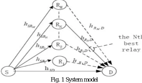
We consider a three node system which consists of a source node S, a destination node D, and N relay nodes as shown in Fig. 1.
Fig. 1 System model
A source node S and a destination node D communicate over a flat Rayleigh fading channel with channel coefficient
ℎ . A number of nodes (i=1,2,….,N,….M) are available to relay the signal from the source node to destination node. The channels coefficients between source and relay areℎ and between relay and source are ℎ , and also the channels are flat Rayleigh fading channels. It is assumed that the channel coefficients are mutually independent and identical or non-identical distributions. In addition, to fading channels are corrupted by additive white Gaussian noise (AWGN) with zero mean and equal variances . All nodes are equipped with a single antenna.
Vol. 4, Issue 8, August 2015
the destination when the highest SNR relay may not be used. The destination combines the two received signals using a technique such as maximal ratio combining (MRC).
The signal received as the destination via direct transmission and via relayed transmission can be written as
= ℎ +
= ℎ +
where is the transmitted signal energy from source and assuming the transmitted signal energy from the relay is equal to that from S. and are AWGN terms. The symbol is assumed to have unit energy.
If the quality of the direct path signals at the destination is insufficient i.e., the SNR of the received signal doesn’t reach the threshold value, (the minimum SNR for which the destination can detect the signal successfully without the need of the relayed signal), then on the second timeslot the Nth best relay is employed to forward the relay signal to D, the signal received at D can then be written as
= ℎ +
where is AWGN on the link between and D .When AF relaying is employed, the Nth best relay is selected to amplify the signal and forward it. = G× , where G is the gain. The feedback (acknowledgment) from the destination is based on a comparison of the received SNR from the source with a threshold , which is the minimum SNR such that the destination can detect the signal successfully without employing a relay signal. For obtaining error free reception we are employing cyclic binary coding and bit interleaving.
To analyze the performance of incremental relaying networks with Nth best relay with AF, the probability density functions (PDF) for the SNR on the S to D link and the SNR from S to D via the Nth best relaymust be obtained. Assuming the SNR on the SD link is γ =ℎ / , the instantaneous SNR on the ith SR link is γ =ℎ / , and the SNR on the ith RD link is γ =ℎ / . The corresponding average SNRs areγ = (ℎ ) / γ =
(ℎ ) / and γ = (ℎ ) / respectively where E( ) denotes expectation. The total number of relays is M.
The PDF of the SNR for the Nth best relay ( ) is obtained by considering the Nth order statistic for a set of independent random vectors. Since the fading coefficientℎ is Rayleigh distributed, has an exponential distribution which can be written as
( ) −
The SNR of the Nth best relay at the destination can be written as
= max
, ,……. + + 1
Where Nth max is the Nth maximum of the value in bracket. Based on this we select the Nth maximum value of SNR and the relay corresponding to Nth maximum is selected for the transmission of data.
IV. STIMULATION RESULTS
Vol. 4, Issue 8, August 2015
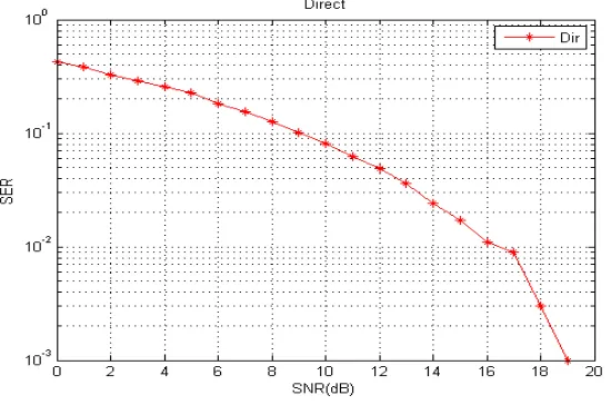
data does not reach the threshold value. According to incremental relaying, if direct transmission is not optimum then it goes for relayed transmission.
Fig. 2 Direct Transmission of Data
Fig. 3 shows the transmission of data via relays when the number of relays are six. The SNR value of the relays are compared with the threshold value. Those with SNR value above threshold will be filtered. From this the Nth best relay will be selected based on the SNR values from source to relay and relay to source.
Fig. 3SNR Vs SER value when number of relays is 6
Vol. 4, Issue 8, August 2015
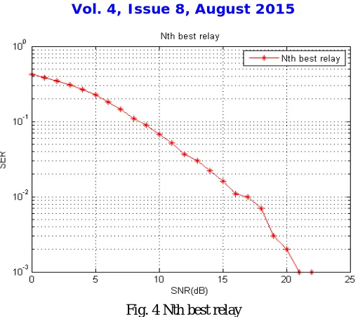
Fig. 4 Nth best relay
In Fig.5, the graph shows the outage probability with doppler spread for proposed scheme and conventional scheme. Rayleigh fading is a small-scale effect. There will be bulk properties of the environment such as path loss and shadowing upon which the fading is superimposed. How rapidly the channel fades will be affected by how fast the receiver and/or transmitter are moving. Motion causes Doppler shift in the received signal components. The figures show the power variation over 1 second of a constant signal after passing through a single-path Rayleigh fading channel with a maximum Doppler shift of 10 Hz and 100 Hz. These Doppler shifts correspond to velocities of about 6 km/h (4 mph) and 60 km/h (40 mph) respectively at 1800 MHz, one of the operating frequencies for GSM mobile phones. This is the classic shape of Rayleigh fading. Note in particular the 'deep fades' where signal strength can drop by a factor of several thousand, or 30–40 dB.
Fig. 5 Outage probability Vs Doppler Spread when N=3 and N=4
Vol. 4, Issue 8, August 2015
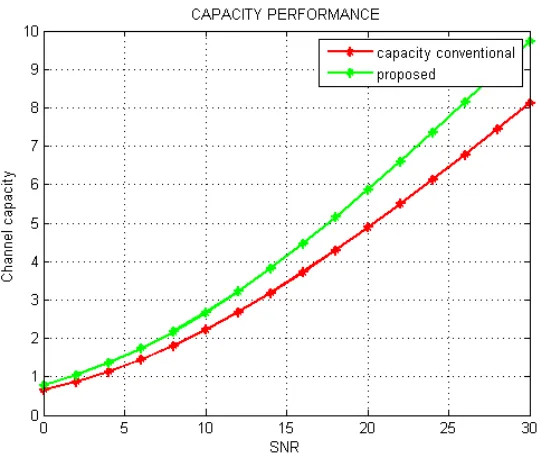
Fig. 6 Channel Capacity Vs SNR
IV.CONCLUSION
Incremental relaying with Nth best relay for Rayleigh fading channel was introduced. Derived the equation for finding the Nth best relay. Stimulated output of functioning of the relay selection. Performance results were presented which show that the incremental Nth best relay protocol can be useful when considering improving the error rate and bandwidth efficiency at the same time comparing to the conventional direct system and relayed system with the Nth best relay when the best relay is unavailable due to scheduling, load balancing, or other issues.
REFERENCES
[1] J. Laneman, D. Tse, and G. Wornell, “Cooperative diversity in wireless networks: Efficient protocols and outage behaviour,” IEEE Trans. Inf.Theory, vol. 50, no. 12, pp. 3062 – 3080, Dec. 2004.
[2] A. Ibrahim, A. Sadek, W. Su, and K. Liu, “Cooperative communications with partial channel state information: When to cooperate?” in Proc. IEEE Global Telecommunications Conference (GLOBECOM ’05), Saint Louis, Missouri, USA, Dec. 2005, pp. 3068 –3072.
[3] S. Ikki and M. Ahmed, “Performance analysis of incremental relaying cooperative diversity networks over Rayleigh fading channels,” in Proc.IEEE Wireless Communications and Networking Conference (WCNC2008), Las Vegas, Nevada, USA, Apr. 2008, pp. 1311 –1315.
[4] H. Long, K. Zheng, W. Wang, and F. Wang, “Approximate performance analysis of the incremental relaying protocol and modification,” in Proc.IEEE 70th Vehicular Technology Conference Fall (VTC 2009-Fall), Anchorage, Alaska, USA, Sept. 2009, pp. 1 –5.
[5] R. Patil, “On throughput performance of decode and forward cooperative relaying with packet combining and ARQ,” International Journal ofComputer Networks and Communications (IJCNC), vol. 4, no. 3, pp. 57–67, May 2012.
[6] K.-S. Hwang, Y.-C. Ko, and M.-S. Alouini, “Performance analysis of incremental opportunistic relaying over identically and non-identically distributed cooperative paths,” IEEE Trans. Wireless Commun., vol. 8, pp. 1953-1961, Apr. 2009.
[7] S. Ikki and M. H. Ahmed, “Performance analysis of cooperative diversity with incremental-best-relay technique over Rayleigh fading channels,” IEEE Trans. Commun., vol. 59, no. 8, pp. 2152-2161, Aug. 2011.