*
Corresponding author: [email protected]
Study on the soft-start process of PSM high voltage power
supply for ECRH
Jian Zhang1, Rui Guan1, 2,Fei Guo1,Yu Zhou1, 2, Haozhang Sun1, Junjiang Wang1, 2, Yiyun Huang1,2 1Hefei Institutes of Physical Science, Chinese Academy of Sciences, Hefei 230031, China
2University of Science and Technology of China, Hefei 230026, China
Abstract. The soft-start process of high voltage power supply (HVPS) based on pulse step modulation (PSM) for ECRH on EAST is introduced, which is the first procedure of system operation. The response process is detailed by proposing DC equivalent circuit model, process analysis and performance comparison is given under the conditions of different soft-start resistor parameters, and the theoretical analysis is proved by the simulation package ANSYS Simplorer simulations. The soft-start resistor is designed for the HVPS of 140GHz ECRH system for a smooth charging without overshoot of the capacitor [6], and the final experimental results show that it is in
agreement with the theoretical analysis and is stable and reliable to the power devices.
Keywords. EAST, ECRH, pulse step modulation (PSM), soft-start
1 Introduction
The HVPS based on PSM[1] technology has the
advantages of fast opening and closing, high reliability and modularization etc., which has been widely used in Tokamak auxiliary heating system. The structure of 140GHz ECRH HVPS system [2, 3] is shown in Fig.1,
which is composed of 10kV breaker cabinets, 10kV contactor cabinets, multi-winding transformers and rectifying modules.
There are two steps to establish output DC voltage of power supply.
1) The first step is that the filter capacitor of rectifier module is charged by closing breaker and contactor.
2) The second step is that the output DC voltage is built by closing IGBT.
When the HVPS is powered up, to limit the inrush current of transformers and the charging current of capacitor, the series resistor needs to be connected in the 10kVAC side or in the module side. There are almost one hundred of rectifier modules in the HVPS system, so the series resistor[4,5,6] in each module will significantly
increase the manufacturing difficulty, volume and cost of modules, therefore the series resistor in 10kVAC side is more economical and feasible[7]. The soft-start includes
two processes: insert and removal of the resistor. In the following, the soft-start process will be analyzed theoretically and be verified by ANSYS Simplorer simulation and experimental results.
Fig. 1. The topology of HVPS for 140GHz ECRH system on EAST.
2 DC equivalent model of rectifier
module
The equivalent circuit with the series resistor which is located in the 10kVAC side is shown in Fig.2.
Fig. 2. The equivalent model of rectifying module.
The AC source charges the capacitor through the soft-start resistor, transformer, and three-phase uncontrolled rectifier, and then the DC output of the rectifying module is controlled by the IGBT switch. The process of charging the filter capacitor is called the soft start process. The parameters of each branch are equal, mutual influence can be ignored, and the current and voltage on each branch are approximately equal, so the model in Fig.2 can be simplified as DC equivalent circuit which is shown in Fig.3.
Fig. 3.The DC equivalent circuit of rectifying module.
The basic parameters of multi-winding transformer are shown in Table 1.
Table 1.The basic parameters of multi-winding transformer.
Primary side Secondary side
Rated power SN 3150kVA
Rated voltage UNL 10kV 600V
Number of Winding 1 44 Short-circuit impedance UK 4%
Field current If 0.73A
When the leakage inductance is converted to DC side, the leakage inductance can be calculated by the conventional method of transformer. The leakage inductance is expressed as follow equation:
𝐿′= [(
𝑈2𝑁𝐿 √3 )
2
𝑆𝑁 3𝑁
]𝑈𝐾
2𝜋𝑓 (1) 𝑈2𝑁𝐿: line voltage of secondary side
N: number of secondary winding
Because the current always flows over two phases, when the filter capacitor is charged, the DC side resistor is two times of it in the AC side.
Equivalent inductance:
L = 2L′ (2) Equivalent resistor:
𝑅 =2𝑁𝑅𝑠𝑜𝑓𝑡
𝐾2 (3)
Rsoft: soft-start resistor
3 The analysis of soft-start process
The soft-start process consists of two steps:
1) The first step is that the soft-start resistor is connected into the circuit, the filter capacitor is charged to the first steady state value through the soft-start resistor.
2) The second step is that the soft-start resistor is removed, so the filter capacitor is charged to the second steady state value.
3.1. The charging process with the soft-start resistor
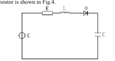
The charging equivalent circuit with the soft-start resistor is shown in Fig.4.
Fig. 4. The charging equivalent circuit with the soft-start resistor.
The transfer function of the filter capacitor voltage and step excitation is established as follow equation.
𝑈𝐶(𝑠) 𝑈𝑖(𝑠)
=
1 𝐿𝐶 ⁄
𝑠2+𝑠(𝑅 𝐿⁄ )+(1 𝐿𝐶⁄ )
(4)
And the characteristic equation of transfer
function is 𝑠2
+ 𝑠(𝑅 𝐿⁄ ) + (1 𝐿𝐶⁄ ) = 0, so
∆= (𝑅 𝐿⁄ )2− 4 1 𝐿𝐶
When ∆< 0, the equivalent resistor satisfies R < 2√LC, the circuit is underdamped. It will cause overshoot of the output voltage. In order to avoid overshoot, ∆
should be more than zero, the equivalent resistor should
satisfy R > 2√LC , so that the circuit is overdamped. Take note of (3), the soft-start resistor can be defined by:
Rsoft>K 2
N√ L
If the resistor is large enough to satisfyR ≫ 2√𝐿𝐶, the RLC circuit can be equivalent to a RC circuit,
so, {UC(t) = U(1 − e −RC1t)
iC=URe− 1 RCt
(6)
U: Input voltage of DC equivalent circuit
The peak current of charging is express as follow equation:
𝑖𝑚𝑎𝑥1= 2𝑁𝑅𝑠𝑜𝑓𝑡𝑈 𝐾2
(7)
In order to ensure that the rectifying bridge and capacitor can withstand maximum current, the charging current must be less than 300A, therefore the soft-start resistor should satisfy:
𝑅𝑠𝑜𝑓𝑡> 𝐾 2U
2𝑁×300 (8)
According to (5), when N=1, 𝐾N2√𝐿𝐶 get the
maximum 𝐾2√𝐿
𝐶 , so the soft-start resistor satisfy:
R𝑠𝑜𝑓𝑡> 𝐾2√𝐿𝐶
The circuit is simulated by selecting different soft-start resistor, the results are shown in Figure 5. According to the design of the module, the simulation parameters are set as follows:
1) Input voltage of DC equivalent circuit U: 1000V. 2) Equivalent inductance of DC equivalent circuit L: 2mH.
3) Filter capacitor C: 10mF.
Fig. 5. The capacitor voltage of different soft-start resistor.
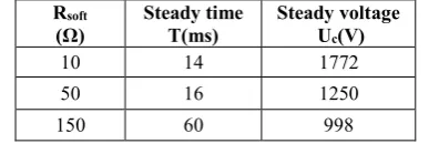
Table 2.The Influence of soft-start resistor on charge voltage.
Rsoft
(Ω) Steady time T(ms) Steady voltage Uc(V)
10 14 1772 50 16 1250 150 60 998
According to Fig.5 and Table 2, when the soft-start resistor is less than K2√L
C which is equal to 124Ω
according to the simulation parameters, the circuit is underdamped, the steady voltage of filter capacitor is larger than 1000V, and furthermore, the overshoot voltage is smaller with the increase of the soft start
resistor. When the soft-start resistor is larger than K2√L C
which is equal to 124Ω, the circuit is over damped, the steady voltage of filter capacitor is about 1000V, and the capacitor is charged without overshoot.
3.2 The charging process of removing the soft-start resistor
When the filter capacitor is charged to the first steady state value, the voltage is less than the rated value because of start resistor voltage drop, so the soft-start resistor must be removed to get the rated value and reduce the power loss. The soft-start resistor is removed by closing S2 in Fig.3, then the capacitor will be charged again to the rated value. The equivalent circuit is shown in Fig.6.
Fig. 6. The removing process of soft-start resistor.
The voltage drop of soft-start resistor which is produced by transformer magnetizing current is∆U = 𝐼𝑓𝑅𝑠𝑜𝑓𝑡, the excitation can be equivalent to:
𝑢𝑖=√2√3𝐼𝑓 𝑅𝑠𝑜𝑓𝑡 𝐾 =
√6𝐼𝑓𝑅𝑠𝑜𝑓𝑡 𝐾
The time domain expression is established as follow equation.
𝐿𝐶𝑑2𝑢𝐶
𝑑𝑡2 + 𝑢𝐶 = 𝑢𝑖 (9)
According to the initial condition of filter capacitor:𝑢𝐶 = 𝑈 −√6𝐼𝑓
𝑅𝑠𝑜𝑓𝑡 𝐾 , C
𝑑𝑢𝐶
𝑑𝑡 = 0, the capacitance
voltage and current are expressed as follow:
{
uC= U −√6IfKRsoftcos√LCt
iC=√6IfKRsoft√CLsin√LCt
(10)
According to (10), the voltage increment of filter capacitor is:
∆𝑢𝐶 =2√6𝐼𝑓 𝑅𝑠𝑜𝑓𝑡
𝐾 (11)
The peak current is expressed as follow equation:
𝑖𝑚𝑎𝑥2=√6𝐼𝑓 𝑅𝑠𝑜𝑓𝑡 𝐾 √
𝐶
𝐿 (12)
In order to ensure that the charging current is less than 300A, the soft-start resistor should satisfy:
𝑅𝑠𝑜𝑓𝑡<300𝐾√6𝐼 𝑓√
𝐿
The circuit is simulated by selecting different soft-start resistor, the selection of resistor need to guarantee that the circuit is over damped. According to the simulation parameters, the soft-start resistor must
be R𝑠𝑜𝑓𝑡> 𝐾2√𝐿𝐶 and the simulation parameters are set
as follows:
1) Input voltage of DC equivalent circuit U: 1000V. 2) Equivalent inductance of DC equivalent circuit L: 2mH.
3) Filter capacitor C: 10mF.
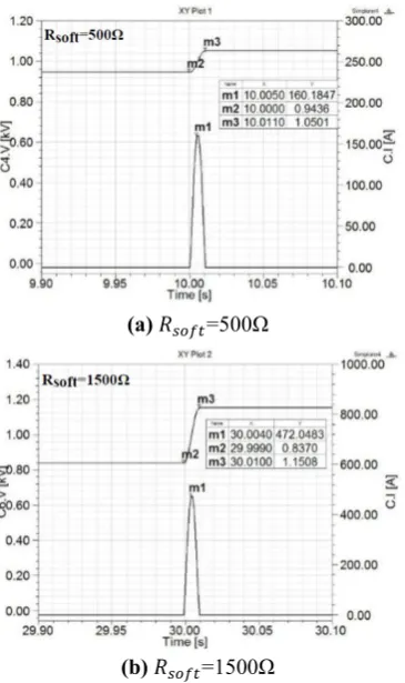
(a) 𝑅𝑠𝑜𝑓𝑡=500Ω
(b) 𝑅𝑠𝑜𝑓𝑡=1500Ω
Fig. 7.The capacitor voltage of removing different soft-start resistor.
Table 3. The Influence of soft-start resistor on charge voltage and current.
Rsoft(Ω) Imax2 (A) U1 (V) U2 (V) △U
500 160 943 1050 107 1500 472 837 1150 313
Imax2: Maximum charging current of removing the
soft-start resistor.
U1: The initial voltage of the filter capacitor before
removing the soft-start resistor.
U2: The steady voltage of the filter capacitor after
removing the soft-start resistor.
△U: The voltage change of the filter capacitor by removing the soft-start resistor.
According to (13), when the soft-start resistor is less than 300𝐾
√6𝐼𝑓√ 𝐿
𝐶 , which is equal to 968Ω, the rectifying
bridge and capacitor can withstand maximum current 300A. Take note of Table 3, when Rsoft=500<968Ω,
Imax2=160<300A, and when R=1500>968Ω, Imax2=472 >300A. According to (12) and Table 3, Imax2 will enlarge
with the increase of the soft-start resistor, and according to (11) and Table 3, △U will enlarge with the increase of the soft-start resistor. So in order to reduce voltage fluctuation of filter capacitor, the soft-start resistor should be reduced as far as possible.
According to the analysis, the design of the soft-start resistor must meet the following conditions. (1)In order to avoid overshoot, the soft-start resistor must satisfy:
R𝑠𝑜𝑓𝑡> 𝐾2√𝐶𝐿.
(2)In order to ensure that the rectifying bridge and capacitor can withstand the maximum charging current, the soft-start resistor must satisfy:
𝐾2𝑈𝑖
2𝑁×300< 𝑅𝑠𝑜𝑓𝑡 < 300𝐾
√6𝐼𝑓√ 𝐿 𝐶 .
4 The resistor design of HVPS for ECRH
system
According to the multi-windings transformer parameters in the HVPS for 140GHz ECRH system, the leakage inductance of transformer can be calculated as follow:
L1= [(
U2N √3)
2
SN 3N
]XN%
2πf = (600
√3)2 [31500003×44 ]×4%
2π×50 =0.6mH
So the equivalent inductance is: L=2L1=1.2mH
To ensure that the output voltage ripple is less than 1%, the filter capacitor is selected as follow:
C=10mF
According to condition (1), in order to avoid voltage overshoot the soft-start resistor must satisfy:
R𝑠𝑜𝑓𝑡> 𝐾2√𝐿𝐶= 111Ω
According to condition (2), in order to limit the maximum charging current the soft-start resistor must satisfy:
5Ω = 𝐾2𝑈𝑖
2𝑁×300< R𝑠𝑜𝑓𝑡 < 300𝐾
√6𝐼𝑓√ 𝐿
𝐶= 1118Ω
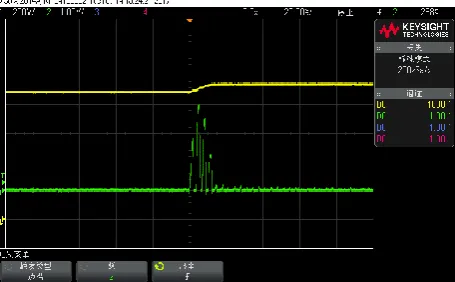
Fig. 8.The capacitor charging waveform with the soft-start resistor.
X-axis: 2s/div
Y-axis: 200V/div, 8A/div
Fig. 9.The capacitor charging waveform of removing the soft-start resistor.
X-axis: 2s/div
Y-axis: 200V/div, 40A/div
In Fig.8, the maximum value of charging current with the resistor is 16A and the first steady state voltage is 870V. In Fig.9, the maximum current value of removing the resistor is 110A and the second steady state voltage is about 930V. The voltage change of the capacitor is about 60V.
According to (7) and (12), the calculation for the maximum value of charging current is 11A and 93A for different process. According to (11), the voltage change is 64V. The experimental results are in agreement with the theoretical analysis.
5 Conclusion
The soft-start process of HVPS based on PSM technology is studied in this paper. A simplified DC equivalent model is proposed, and the transient and steady state responses of the soft-start process are analysed in detail. The qualifications are obtained and proved by simulation results. The soft-start resistor has been designed for the HVPS of the 140GHz ECRH system, and the final experimental results show that it is coincident with the theoretical analysis.
This work was supported by the National Mangenetic Confinement Fusion Science Program of China under contract No. 2015GB103000, the National Key Research & Development Plan 2017YFE0300401, and CAS Key Technology Talent Program.
References
1. X. Hao, et al., Design and application of a new control system for Tokamak ECRH power supply [J]. Radiation Effects & Defects in Solids, (3-4):1-10. (2016)
2. J. Zhang, et al., The Design of PSM-Based ECRH Power Supply Control System [J]. Journal of Power & Energy Engineering, 04(4):91-102. (2016) 3. S. Ma, et al., Analysis and Design of the Module for
PSM High-Voltage Power Supply [J]. Journal of Fusion Energy, 34(2):261-266. (2015)
4. S.Ma, et al., High-voltage power supply for ECRH system on J-TEXT Tokamak[C]// Fusion Engineering. IEEE, 1-5. (2013)
5. L. Xia, et al., Analysis of the Soft-Start Circuit of the High Voltage Power Supply Based on PSM Technology [J]. IEEE Transactions on Plasma Science, 42(4):1026-1031. (2014)
6. X. Hao. The Transient Analysis of PSM High Voltage DC Power Supply and the Research of Its Control Strategy [D]. University of Chinese Academy of Sciences. (2012)