Introductory Numerical Study on Supersonic Ejector Working
with R32
Lukas Vojta1, Jan Kracik1,* and Vaclav Dvorak1
1Department of Power Engineering Equipment, Faculty of Mechanical Engineering, Technical University of Liberec, Studentska 2, 46117, Liberec, the Czech Republic
Abstract. Nowadays, there is an increasing demand for devices which work efficiently with the smallest possible consumption of energy. In this regard, incorporating ejectors seems to be an interesting choice. This paper describes the numerical analysis of the flow in a supersonic ejector working with R32 (difluoromethane) as the working fluid. The ejector geometry under investigation in this paper has already been experimentally analysed, however, air was used as the working fluid. Therefore, this paper deals with a numerical analysis of the same geometry but with a different working fluid. Furthermore, the design of the ejector enabled the adjustment of a particular distance of the motive nozzle from the beginning of the mixing chamber, i.e. the nozzle exit position (NXP). This work examines the ejector numerically for eleven values of back-pressure with the NXP of two millimetres; consequently, the performance line of the ejector with fixed boundary conditions at both inlets was obtained. Finally, the obtained results are discussed and some recommendations for future research have been made.
1 Introduction
These days, there is an increasing demand for devices which work efficiently with the smallest possible consumption of energy. In this regard, incorporating ejectors in refrigeration cycles seems to be an interesting choice. There have been many studies on ejectors and ejector refrigeration systems so far. For example, the review carried out by Sun and Eames [1] could be mentioned. This review especially deals with ejectors in general. As regards ejectors for refrigeration applications, an extensive review by Besagni, Mereu and Inzoli was performed [2].
An ejector is a device that consists of several parts. The main part is a convergent-divergent nozzle which enables the reach of supersonic velocities at its exit, and further downstream. Achieving such high velocities is possible due to the sufficient pressure gradient between two certain points downstream, and upstream, the nozzle and a proper shape of the nozzle. If the nozzle exit is placed in the mixing chamber, the secondary stream is entrained inside the mixing section due to low pressure downstream the nozzle. As a result, it is possible to create a very high vacuum. Even a higher vacuum can be achieved when using several ejectors that are connected in series. In addition, the primary and secondary medium can either be the same or different. There exist also ejectors working with two different phases of a certain medium.
Ejectors, like any other devices, have their advantages and disadvantages. The main advantage of ejectors seems to be the absence of any moving
mechanical parts. Furthermore, ejectors are also easy to manufacture - being low-cost and very reliable. On the other hand, their essential disadvantage is their generally low efficiency, which reaches a maximum of thirty percent and, therefore, substantially limits their use in more industrial applications. Due to the low efficiency of ejectors, their use is limited, in most cases, to the industry sectors where a sufficient amount of primary medium is available, or where the use of other devices is not possible. [3]
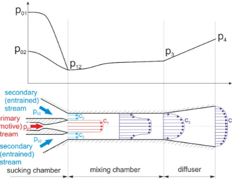
mixing chamber, the static pressure of the mixed stream is further increased to pressure p4, and the efficiency of the ejector is also increased. The entire process in the ejector is illustrated in Figure 1 [3] [4] [5].
Fig. 1. Static pressure distribution and velocity profile development along a mixing chamber and a diffuser.
2 Applications of ejectors
As mentioned in the previous section, ejectors are foremost used in applications where a sufficient amount of primary medium or the operating costs is advantageous. Some specific examples can be for instance: developing a high vacuum in compressed-air operations; ejector cooling systems, where an ejector replaces a compressor; creating a vacuum, by setting several ejectors in series, a very low absolute pressure can be created; transport of substances or materials that could damage the moving parts of pumps by their properties; pumping liquids from depths that do not allow the use of a pump; propulsion of aerodynamic wind tunnels, both subsonic and supersonic.
As regards refrigeration applications, ejectors are used where a heat source is available at a slightly higher temperature level (100 °C – 120 °C). Such applications can be the use of air conditioners in combination with thermal solar panels - cooling is most utilized at the time it is most desirable [3] [6].
3 Theoretical background
Fig. 2. Control volume of a mixing chamber of general shape
The control volume, for which the set of balance equations has been formulated, illustrates Figure 2. A general shape of a mixing chamber has been considered in this study, where at the inlet the total cross
section is equal to the sum of the cross-section of the motive nozzle A1 and the suction cross-section A2 [4].
The outlet cross-section is then denoted A3. The governing equations stated in this study are derived for the stationary mixing of the ideal fluid. For the general shape of the mixing chamber, three main governing equations can be formulated. The first equation is the continuity equation and its form is as follows:
3 3 3 2 2 2 1 1
1cA c A c A
. (1)
The second equation is the momentum equation. Assuming that the pressures of both streams will have the same value at the inlet of the mixing chamber. Pressure p12 is then the common expansion pressure of both streams. The momentum equation will then be in form:
SKx A SKx 3 3 3 3 2 2 1 1 2 2 11c mc pA p A mc p A p(x)dA
m , (2)
where the integral on the right hand side represents the compressive force on the projected cross-section ASKx of the mixing chamber in the "x" direction from the general pressure p(x) on the wall of the mixing chamber.
The last equation is the energy equation which assumes the adiabatic flow in the mixing chamber.
03 2 1 02 2 01
1h mh (m m)h
m , (3)
where h01, h02 and h03 are the total enthalpies of the primary, secondary and mixed stream, respectively.
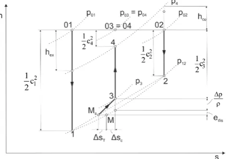
The processes which occur in an ideal ejector without friction losses are shown in Figure 3. The primary (motive) and secondary (entrained) stream expand to the common expansion pressure p12 from their total pressures p01 and p02 on the isobar to the points 1 and 2, respectively. The ideal mixing point Ms lies on the line of points 1 and 2, the real mixing point M is shifted in the direction of higher entropy due to the losses in the motive nozzle and suction part as well as due to inequality of static temperatures of both streams. Mixing increases entropy and increases the pressure of the expanded flows to the pressure p3. Then, the pressure is further increased in an ideal diffuser. The pressure at the diffuser output corresponds to the pressure p4.
From Figure 3, a relationship for the efficiency of an ejector can be obtained and its form is as follows,
01 02 1 01 4 1 02 4 1 2 EJC T T p p 1 1 p p m m
, (4)
where 1 2 m m
is the entrainment coefficient or ratio defined as 1 2 m m
, (5)
Fig. 3. Processes in an ideal ejector in the enthalpy-entropy diagram for the same total temperature of primary and secondary stream (T01 = T02).
5 Numerical modelling
The numerical model was generated by Ansys Workbench software. The geometry and mesh were created in SpaceClaim and Ansys Meshing, respectively. As a result, the two-dimensional hexahedral axisymmetric structured mesh with nearly 70,000 elements was created. In order to assess mesh dependency on the final solution, several mesh densities were examined. Additionally, the refined mesh was created in the vicinity of the motive nozzle. The values of y+ on the ejector walls were in most of the cells below value of three. The main dimensions of the ejector model are illustrated in Tab. 1. Boundary conditions of the ejector model illustrates Tab. 2.
Table 1. Main geometry parameters of ejector.
According to the work by Nguyen [7] there is no significant error between the ideal and real gas approach calculations in regard to ejectors, the ideal gas law approach was used for all calculations of the refrigerant R32 in this paper. Moreover, it should be mentioned that using the real gas approach can fail to converge for some refrigerants, especially for higher motive pressures. In addition, if it converges without difficulties, there can be significant discrepancies between the solution for the real gas and ideal gas approach. Except for cp, which was solved by the piecewise-polynomial function, all variables were considered as constant. Additionally, the calculations were performed as transient with the density-based solver. The time step was chosen less than 10-3 s and maximum of 20 iterations were performed at each time step. The number of time steps depended on the speed of convergence of the solution. All calculations were performed with the second order upwind scheme. As a viscous turbulent model, the k-ω
SST model was employed. Furthermore, the heat transfer through the walls was considered to be negligible, and thus the walls were assumed to be adiabatic.
It is worth noting that some calculations on the same geometry has already been performed and presented by Kracik and Dvorak [6]; however, air was used as the working fluid.
Fig. 4. Schematic of the ejector model with boundary conditions.
Table 2. Boundary conditions of the ejector model.
The governing equations can be written in the form as follows:
ρu 0 xt
ρ
i i
, (6)
j ij ij j j
i j
i x
τ pδ x u
ρu x ρu
t
, (7)
0
ij i j j 0 j j
0 x ρu e u p q uτ
ρe
t , (8)
ρrT
p . (9)
As outlined above, these equations are solved by means of the commercial CFD software Ansys Fluent [8].
6 Results and discussion
Figure 5 demonstrates dependencies of the primary, secondary and mixed flow mass flow rate on relative
Ejector parameter dimension (mm)
Nozzle throat diameter 3.50
Nozzle exit diameter 4.67
Mixing chamber diameter 8.00
Mixing chamber length 98.00
Diffuser outlet diameter 16.00
Diffuser length 38.10
Boundary conditions p (kPa) T (K)
Primary inlet 397 323
Secondary inlet 97 295
back-pressure, i.e. the absolute back-pressure divided by the absolute stagnation pressure of the entrained or secondary flow. The primary flow is not significantly changed with back-pressure, however, there can be seen slight differences. The maximum difference between the values of the primary mass flow rates is Δm1 = 7.6e-5 kg ·s-1. As the computational mesh was identical for all cases, the imbalance is likely caused by the numerical precision. The mean value of the primary mass flow rate is 0.011 kg ·s-1. As regards the secondary mass flow rate, the mean maximum value in the on-design regime is 0.0075 kg ·s-1. The maximum value of the mixed flow is then given as a sum of the primary and secondary flow and is approximately 0.0185 kg ·s-1.
Fig. 5. Courses of the primary, secondary and mixed mass flow rate.
Fig. 6. Performance line of the ejector.
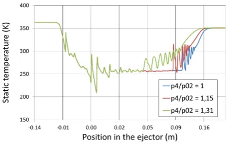
Fig. 7. Static temperature distribution on the ejector axis for the lowest three back-pressures in the on-design regime.
Fig. 8. Contours of temperature for relative back-pressure p4/p02 = 1.31 (127 kPa abs) in the vicinity of the motive nozzle.
Fig. 9. Approximate illustration of the state of the refrigerant before the shock wave in pressure – enthalpy diagram.
Fig. 10. Contours of Mach number for back-pressure p4/p02 = 1.57, (152 kPa abs).
Fig. 12. Contours of Mach number for relative back-pressure p4/p02 = 1.77 (172 kPa abs).
The performance line of the ejector can be seen in figure 6. Based on the calculated values of the mass flow rates, the maximum entrainment ratio in the on-design regime is approximately 0.68. This value remains almost unchanged up to the relative back-pressure 1.46 (142 kPa abs) and for higher values starts rapidly decreasing. As a result, this ejector with this type of refrigerant can only be used for fairly small back-pressures, which limits its use and makes it more difficult to incorporate to a refrigeration system. For the relative back-pressure higher than 1.62 (157 kPa abs), the ejector stops working properly and almost no or negligible amount of the secondary stream is entrained into the mixing chamber. Consequently, the entrainment ratio falls to values close to zero. For even higher values of back-pressure the secondary stream tends to flow backwards, i.e. malfunctioning of the ejector, and the entrainment ratio reaches negative values.
Figure 7 shows the static temperatures on the ejector axis as a function of position in the mixing chamber. Three cases in the on-design regime with the lowest static temperatures are illustrated. The lowest temperature was reached for the relative back-pressure of 1.31 before the shock wave inside the divergent part of the motive nozzle and was approximately 229 K, see figure 8. This fact could, in some cases, lead to condensation. However, the condensation phenomenon does not occur in this case since the refrigerant is in a state of a superheated vapour as shown in figure 9. The corresponding absolute static pressure is approximately 25 kPa.
Figure 10 to 12 show contours of Mach number for the relative back-pressure of 1.57, 1.62 and 1.77, respectively. In figure 10, it is obvious that a small amount of the secondary stream is still entrained into the mixing chamber. On the other hand, figure 11 shows the regime for relative back-pressure of 1.62 (157 kPa abs) and almost no secondary flow is entrained by the primary flow. It is worth noting that according to figure 6 there can still be seen a slightly positive entrainment ratio. The regime depicted in Figure 12 shows that some amount of the secondary stream flows backwards.
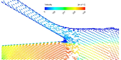
Moreover, the three above mentioned regimes are also shown in figure 13 to 16 in more detail. Here, vectors of velocity magnitude are shown in the vicinity of the trailing edge of the motive nozzle. The backflow can be seen in figure 16.
Fig. 13. Vectors of velocity magnitude for relative back-pressure p4/p02 = 1.57, (152 kPa abs) in the vicinity of the motive nozzle.
Fig. 14. Vectors of velocity magnitude for relative back-pressure p4/p02 = 1.62, (157 kPa abs) in the vicinity of the motive nozzle
Fig. 15. Vector of Velocity magnitude for relative back-pressure p4/p02 = 1.77, (172 kPa abs) in the vicinity of the motive nozzle.
7 Summary and conclusion
An ejector performance line for two crucial values of back-pressure was obtained. The first value corresponds to the transition between on-design and off-design regimes where the entrainment ratio started to decrease significantly. The value of relative back-pressure was in this case approximately 1.46 (142 kPa absolute). The other crucial value of back-pressure corresponded to the point where the ejector stopped working properly and the secondary stream was not entrained into the mixing chamber anymore and started moving in the opposite direction. The value of this relative back-pressure was found out to be slightly higher than 1.62 (157 kPa absolute).
The maximum entrainment ratio was around the value of 0.68. This value corresponds to the on-design regime of the ejector. Furthermore, it was shown that for slightly higher values of back-pressure the entrainment ratio starts to decrease rapidly. As a result, the range of operating back-pressures is relatively small. This fact could limit the use of the refrigerant in a real-life application of refrigeration. On the other hand, there is still very desirable further research on this topic.
This publication was written at the Technical University of Liberec as part of the project “Experimental and numerical investigation in applied fluid mechanics and energy devices, no. 21124" with the support of the Specific University Research Grant, as provided by the Ministry of Education, Youth and Sports of the Czech Republic in the year 2018.
References
1. DW Sun and IW Eames, Journal of the Institute of Energy68, (1995): 65–79
2. Giorgio Besagni, Riccardo Mereu, and Fabio Inzoli, Renewable and Sustainable Energy Reviews 53, (2016): 373–407
3. Vaclav Dvorak, Research and optimization of flow in ejectors. Habilitation thesis, (2011), In Czech 4. Vaclav Dvorak, Introduction to flow of compressible
fluids, Technical University of Liberec, (2015). ISBN 978-80-7494-231-0
5. Vaclav Dvorak, Flow in nozzles and diffusers, Technical University of Liberec, (2015). ISBN 978-80-7372-457-3
6. Jan Kracik and Vaclav Dvorak, EPJ WoC 143, (2017)
7. Nguyen Vu Van and Jan Kracik, , Experimental Fluids Mechanics, (2017): 483–489