Differential Fault Analysis of AES: Towards
Reaching its Limits
Sk Subidh Ali1, Debdeep Mukhopadhyay1, and Michael Tunstall2
1
Department of Computer Sc. and Engg, IIT Kharagpur, West Bengal, India.
{subidh,debdeep}@cse.iitkgp.ernet.in 2
Department of Computer Science, University of Bristol, Merchant Venturers Building, Woodland Road, Bristol BS8 1UB, United Kingdom.
Abstract. In this paper we present a theoretical analysis of the limits of the Differential Fault Analysis (DFA) of AES by developing an inter-relationship between conventional cryptanalysis of AES and DFAs. We show that the existing attacks have not reached these limits and present techniques to reach these. More specifically, we propose optimal DFA on states of AES-128 and AES-256. We also propose attacks on the key schedule of the three versions of AES, and demonstrate that these are some of the most efficient attacks on AES to date. Our attack on AES-128 key schedule is optimal, and the attacks on AES-192 and AES-256 key schedule are very close to optimal. Detailed experimental results have been provided for the developed attacks. The work has been compared to other works and also the optimal limits of Differential Fault Analysis of AES.
Keywords: AES , AES key schedule , Differential Fault Analysis , Fault Model
1
Introduction
Fault attacks were first proposed by Bonehet al. [7] where the author showed
that if a fault could be introduced into a microprocessor whilst it is generating an RSA signature the entire private key can be retrieved. In the same year, Bihamet
al. proposed a different form of the attack [4], where they combined the concept of fault analysis and differential cryptanalysis to propose theoretical attacks on DES, which is typically referred to as Differential Fault Analysis (DFA).
the techniques to break the 128-bit version of AES. The attack required around 250 faulty ciphertexts to reveal the AES-128 key. This attack was improved by Bl¨omer et al. [5] which required around 128 to 256 faulty ciphertexts. Dusart et al. in [10], proposed an attack by inducing faults anywhere between the eight
round and ninth round MixColumnsoperations, which required only 40 faulty ciphertexts.
Finally, Piret et al. in [23] proposed a fault attack using only two faulty
ciphertexts. Moradi et al. [20], proposed a more generalized fault attack by
considering two different fault models. In the first, the authors consider one out of four targeted bytes are corrupted and in the second model the author consider that all four targeted bytes are corrupted. For the first fault model the attack required around four faulty ciphertexts whereas in the second fault model the attack requires around 1500 faulty ciphertexts. Beside these DFA attacks there were some practical results [1, 2, 13, 25, 26], where the authors have shown that the required fault induction is indeed possible by inexpensive devices.
There are two more versions of AES: AES-192 and AES-256. Initially, it was assumed that attack proposed by Piretet al. can be extended to these two
versions of the AES with little modification. However, this assumption has been shown to be wrong. In 2009, Liet al. [18] proposed a complete attack on
AES-192 and AES-256. This attack required 16 or 3000 faulty ciphertexts depending on the fault model. Subsequently, many attacks were proposed on AES-192 and AES-256 [14,16,27]. The most recent among these attacks is an attack proposed by Kim [16], which only requires two faulty ciphertexts to uniquely determine the AES-192 key and three faulty ciphertext to retrieve the 256-bit key AES-256. Recently, there has been a significant research on the AES key schedule. Chen
et al. [8], improved Giraud’s attack [9] and showed that the proposed attack can
retrieve the AES-128 key by inducing faults in 9-th round key and requires less than 30 faulty ciphertexts. Peachamet al. [22], considered a different fault
model where a fault is induced while the ninth round key is being generated. Therefore, the induced fault subsequently propagated to the tenth round key. Peacham’s attack required only 12 faulty ciphertexts to retrieve the AES-128 secret key. Takahashi et al. [28], proposed a generalized attack that required
only two faulty ciphertexts to reduce the number of key hypotheses for a AES-128 secret key to 248. Other variants of this attack were presented that, using
four faulty ciphertexts, reduce the number of hypotheses to 216 or, using seven
faulty ciphertexts, determine the secret key. Kimet al. [17] proposed an improved
attack on AES-128 key schedule which required only two faulty ciphertexts to reduce the key space to 232. Recently, Kim proposed a different attack on
AES-128 key schedule by inducing single byte fault at the first column of eighth round key, that requires two faulty ciphertexts to uniquely determine the secret key [15].
Exploiting faults induced in the key schedule of AES-192 and AES-256 has received less attention in the literature. Floissacet al. first proposed an attack
instantiations of the block cipher. In both the cases their attack required 16 faulty ciphertexts to retrieve the secret key. This attack was improved upon by Kim [15], who proposed an attack that required between four and six faulty ciphertexts to uniquely determine a AES-192 secret key and four faulty ciphertexts to uniquely determine a AES-256 secret key.
The attacks described above show a gradual reduction in the data complex-ity of differential fault analysis. However, there is no theoretical analysis which clearly shows the limits of these attacks. There is one contribution by Gomisawa
et al. [19] that shows the limits of the attacks performed on AES where faults
are injected into intermediate states of the block cipher but the analysis is based on existing attacks. There is no clear explanation of the limits of attacks on the AES key schedule so that one cannot be sure whether the existing attacks on the AES key schedule have reached limits.
In this paper, we first theoretically analyze the limits of differential fault analysis of AES. We then describe attacks based on faults in the intermediate states of AES-128 and AES-256 and show that these attacks have reached their limits. This implies that theses attacks cannot be optimized further. We then propose three more attacks on the key schedule for the three different versions of AES and show that the attack on AES-128 key schedule reaches its theoretical limit. However, the proposed attack on the AES-192 and AES-256 key schedule is the most efficient attack to date but does not reach the theoretical limit.
2
Preliminaries
2.1 AES
The Advanced Encryption Standard (AES) is a 128-bit symmetric key block cipher. It has three different versions namely: AES-128, AES-192 and AES-256 that have three different key lengths of 128, 192, and 256 bits respectively. The intermediate results are represented by 4×4 state matrix, where each of its elements is an 8-bit value. The internal operation of AES is divided into identical round functions, where the number of iterations of a this round function varies depending on the bit length of the secret key. That is, AES-128 has 10, AES-192 has 12 rounds and AES-256 has 14 rounds. All the round functions consist of following four transformations, except the last round that omits theMixColumns
operation:
– SubBytes: A byte-wise substitution, where each element of the state ma-trix is replaced by its inverse and followed by an affine mapping. All the operations are underF28.
– ShiftRows: A cyclic shift of i-th row by i bytes towards left (we number the rows from zero to three).
– MixColumns: A column-wise linear transformation of the state matrix. Each column of the state matrix is considered as a polynomial of degree 3 with coefficients in F28 and multiplied by the polynomial {03}x3 +{01}x2+
– AddRoundKey: In this transformation a 128-bit round key is XORed with the 128-bit state.
There is one additionalAddRoundKeyoperations at the beginning of the first round. The round keys are generated by the AES key scheduling algorithm, as shown in Algorithm 1. The round keys are generated from the master key K where Nk, Nr and Kr represent the key length in bytes, number of rounds
and ther-th round key respectively. For more details one can refer to the AES specification [11].
Algorithm 1:AES Key Scheduling Algorithm
Input:Kthe initial key of lengthNkbytes
Output:Krthe round key where 0≤r≤N r
for i= 0toNk−1do
W[i]← {K[4∗i], K[4∗i+ 1], K[4∗i+ 2], K[4∗i+ 3]} end
fori=NktoNb∗(Nr−1)do
temp←W[i−1]
ifimodNk= 0then
temp←SubW ord(RotW ord(temp))⊕Rcon[i/Nk]
end
else if Nk>6andimodNk= 4then
temp←SubW ord(temp)
end
W[i]←W[i−Nk]⊕temp
end
returnW
2.2 Notations Used
In the rest of the paper we refer to theSubBytes, ShiftRows, andMixColumns
operations asSB, SRandM Crespectively and their corresponding inverse func-tions asSB−1, SR−1andM C−1.
The AES is typically considered to operate on a 4 matrix referred to as a state matrix. A given byte in a state matrix will be indexed by its row i and column j. The notation used in this paper takes the form:
Ci,j : The{i, j}byte of the ciphertextC.
C∗
i,j : The{i, j}byte of the faulty ciphertextC∗.
Kr
i,j : The{i, j}byte of ther-th round keyKr
where 0≤i, j≤3.
3
Fault Model Used
computation of the AES block cipher. In this paper we consider both attacks that affect the AES state matrix and the attacks that affect the AES key schedule. In each case we consider the attack on all three versions of AES: AES-128, AES-192 and AES-256.
In the case of attacks that could be applied to AES-128 and AES-192, we assume that an attacker can induce single byte fault between the MixColumns
operations in roundsNr−2 andNr−3. In the case of AES-256 we assume that
an attacker can induce faults at two different locations; between theMixColumns
operation in rounds Nr−2 andNr−3 and between theMixColumnsoperation
in roundsNr−3 andNr−4.
While considering the attack on AES key schedule, we assume a similar fault model. For AES-128 and AES-192 we assume that an attacker can induce a single byte random fault in the first column of KNr−2. In AES-256 we assume two different fault models: in the first one a fault is induced in the first column of KNr−2 and in the second one a fault can be induced in the first column of KNr−3.
4
Estimating the Limits of DFA on AES with Single Byte
Faults
In this section, we analyze the limits of DFA on the AES algorithm. The proofs are based on reduction techniques: we reduce an adversary against AES using conventional cryptanalysis to an adversary in the DFA setting. First, we reduce a collision based adversary, Advcol to a AdvDF Astate which targets a fault in the
state matrix of AES. Next, we show a reduction of a related key adversary of AES, AdvRKey to a DFA adversary which exploits faults in the key-schedule,
AdvDF Akey . The adversary Advcol is defined to be an attacking algorithm which
attacks AES by first varying the plaintext and finding a pair which collides by having a state with a small difference at a chosen point in the algorithm. On the other hand, the adversary AdvRKey obtains a key pair which is related in the
sense that the key scheduling generates fixed difference at a chosen round. The attacker has the ability to obtain encryptions under both the related keys and arbitrary chosen plaintexts. It is assumed that such classical adversaries against AES are not successful in reducing the worst case key space of AES. Further, the adversaries have no other means of inducing such collisions except exhaustive search. We establish the optimal complexities of the DFA adversaries by arguing that if there is a more efficient DFA adversary then the reduction proofs lead to the definitions of classical adversaries which reduce the key space of AES from the worst case complexities, which is assumed to be not possible in this work.
4.1 Limits of DFA on AES States
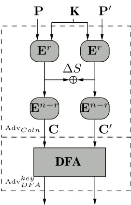
Fig. 1 shows the construction of the adversaryAdvcolusing the adversaryAdvstateDF A
Advcol to the adversaryAdvstateDF A. The reduction starts byAdvcolsearching for a
pair of plaintextsP andP′ such that after a particular roundra target
differ-ence ∆S is obtained. If the probability of obtaining such a pair is Pr(∆S), the expected number of pairs required to obtain at least one pair with the required property is 1
Pr(∆S). For each such guessed pair, the adversaryAdvcol obtains a
pair of ciphertexts, C =En(P), and C′ =En(P′) where E is the AES round
applied forntimes. It then invokesAdvstate
DF A with the pairC andC′.
It may be observed that if the pairP andP′ leads to the desired difference
∆Sat the output of roundr, then the ciphertext pairs (C, C′) are exactly same
as in a DFA. This is because in a DFA, the induced fault during the execution of E will generate a difference∆S at the round r, which will lead to the same faulty ciphertext C′. However the adversaryAdvcol has no way of determining
that the desired fault has occurred, and has to make expected 1
Pr(∆S) number of
trials. Thus if theAdvDF Astate reduces the search space of the key toKl, then the
search space of AES with regard to Advcol is on an average Pr(1∆S) ·Kl. If we
denote the security level of AES as Ks, then Ks is at most Pr(1∆S) ·Kl. Thus,
Ks≤ Pr(1∆S)·Kl, orKl≥Ks·Pr(∆S). Hence, an optimal DFA on AES would
reduce the search space of AES key to Ks·Pr(∆S).
K
DFA
E
rE
n−rE
n−rE
rP
′P
C
C
′∆
S
AdvColn
AdvkeyDF A
We assume that AES is theoretically unbreakable, i.e. there is no attack that would require less time complexity than an exhaustive search3. Then in
the case of AES-128 Ks= 2128. In conducting DFA on AES-128, a single byte
fault is induced in the input to the eighth round. Therefore, ∆S is a single byte difference at the input to the eighth round. The probability that the two plaintextsP andP′ collide at the beginning of a round in 15 bytes out of 16 is 2−120⇒K
l= 2−120·2128 ⇒Kl= 28. This implies, the state-of-art DFA using
a single-byte fault cannot reduce the search space of AES-128 to less then 28. If
it does then Ks<2128 which means the security level of AES-128 is less than
128 bits which contradicts our assumption. Therefore, the lower limits of a DFA using single-byte fault is 28.
This hypotheses is also true for the other two version of AES: AES-192 and AES-256. In case of AES-192, Ks = 2192. Therefore,Kl = 2192−120 = 272, i.e.
a single byte fault induction can reduce the search space of AES-192 key to 72-bit which is the minimum limit. Similarly, for AES-256,Ks= 2256. Therefore,
Kl= 2256−120= 2136.
Note
In this paper we only consider the single byte fault model. However, our analysis is also true for multi-byte DFA as proposed in [24]. In case of the diagonal attack of [24], the difference is considered across a diagonal of the AES state matrix before the input of the eighth roundMixColums. The diagonal fault attack uses the observation that the faults in the diagonals adjusts to columns at the input of the ninth round. The subsequent MixColumns produces similar relations as the single byte DFA on AES-128 state, which are exploited to retrieve the key. However, the attacks proposed in [24] are not optimal in the sense described in this paper. They do not use the inter-relationships of the faults at the output of the eighth roundMixColumnsand hence can be further optimized depending on the number of bytes corrupted in the diagonals. These optimized attacks are presented in [1], and their optimality can be argued in a similar fashion.
According to our analysis, if the induced fault infectsibytes in the required state matrix, then the optimal attack result is given byKs·P(∆S), where∆S
is the required difference which can be of i bytes. In the case of AES-128, the optimal limit is given by 2128· 1
2128−8·i = 28·i.
Therefore, for a diagonal attack, depending on the value ofi, the results may vary. For example, for single byte fault, the optimal limit is 28. Similarly, when
the fault affects all the four bytes of the diagonal, the optimal limit of the attack is 232, as the difference is in four bytes.
The same analysis also true for two diagonal and three diagonal attacks. The optimal attacks complexities are mentioned in Table 2, and it shows that the
3
improvement in [1] indeed achieves the optimal complexities of the Diagonal attacks published in [24].
4.2 Limits of DFA on AES key schedule
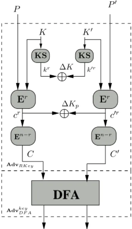
A similar analysis helps to compute the optimal complexity of a DFA on the AES key-schedule. For this purpose, we reduce a related key adversaryAdvRKey
to an adversaryAdvkeyDF A, which performs DFA on AES exploiting faults in the key-schedule of AES. The related key adversary has the ability to obtain encryp-tions with related keys, the unknown key and a related key to the unknown key (as introduced by Biham [3]). The encryptions are performed through suitable oracles for encrypting using related keys.
The relation in this case gives a key K′ such that the key-schedule will
generate a required difference∆K in ther-th round key. It may be noted that ∆K is not a fixed value, but shall be a byte-wise difference (as described in Section 7). For example, for AES-128 ∆K is such that the first row of the difference of the 8-th round key is the bytesa, a, a, a, whereais any byte.
The attackerAdvRKey also attempts that the
Er(P, K)⊕Er(P′, K′) =∆KpwhereEris the output of ther-th round after the
addition of ther-th round key. For this the attacker starts to vary the plaintextP′ and obtain the required difference in the state matrices. Note that the difference ∆Kp indicates that the difference is not necessarily the same difference as∆K,
but a similar difference. Thus in the example of the attack on AES-128, the corresponding differential is such that the first row difference isb, b, b, b, where b is any byte, not necessarily the same as a. The probability of random two plaintexts P and P′ to create the above difference is Pr(∆Kp). However the
adversaryAdvRKey has no way of determining that the required difference has
occurred, and hence has to make Pr(∆K1 p) expected number of choices ofP′.
It thus creates an expected 1
Pr(∆Kp) ciphertexts,C
′and invokes the adversary
AdvDF Akey with the pairs C and C′. It may be noted that it is expected that there will be one pair where the required difference in the state matrices is created. Under this situation the view ofAdvDF Akey is exactly the same as in a DFA targeting the AES key scheduling. This is because the keysKandK′are related
such that after ther-th round the difference as required in the DFA exists and the plaintext pair ensures that the difference in the state matrix is also identical to the DFA. Thus if the AdvDF Akey reduces the key-space toKl, then the search
space of the AES key wrt.AdvRKey is Pr(∆K1 p)·Kl. Like before, if we denote the
security margin of AES asKs, thenKs≤ Pr(∆K1 p)·Kl ⇒Kl≥Ks·Pr(∆Kp).
Thus an optimal DFA on the AES state isKs·Pr(∆Kp).
DFA
KS KS
Er
Er
En−r
En−r
∆Kp ∆K
cr
P P′
K K′
C C′
k′r
kr
c′r
AdvRKey
Advkey DF A
Fig. 2.Related key based DFA
in each of the three rows). Fig. 3(a) shows the faults in the 9-th round key wherea, b,and care the fault values. The probability of getting such difference using a pair of plaintexts is given by (255)(28)123·(218)4 ≈ 21041 .Therefore, we can write
Kl= 2128−104= 224. This implies, the lower limit of this attack is 24-bit using
a single faulty ciphertext.
b
c
a
a
a
a
b b b
c
c
c
c
(a) 3-Byte Fault inK9
a a
b b
(b) Byte Fault in K10
1,0
a a a a
(c) Byte Fault in K12
1,0
In this paper we consider the single-byte fault model. Therefore, if we consider that a single-byte fault is induced in the first column ofK9 the values ofb and
c becomes zero in Fig. 3(a). So, only the first row differences will remain. The probability of getting the four byte difference in a particular row using a pair of plaintexts is given by (255)232 ·
1 296 ≈
1
2120. The lower limitKl= 2128−120= 28.
Therefore, in case of single byte fault, the attack should reduce the AES-128 key space to 28.
Floissacet al. showed a single byte fault analysis on AES-192 and AES-256
key schedule where the fault is induced in 10-th and 12-th round key respectively (Fig. 3(b) and Fig. 3(c)) [12]. It is clear from Fig. 3(c), that a single-byte fault induction in AES-256 key schedule should reveal 120 bits of information on the key. However, in the case of AES-192 the required difference can be generated using a pair of plaintexts with probability (255)(28)42 ·2196 ≈ 21121 . Therefore, the
lower bound of attack on AES-192 key schedule is given byKl= 2192−112= 280.
From the above analysis we come to know the maximum information leakage from a DFA based on single byte-fault induction. Using this information we can also get the optimum attack results. Here the optimum results are based on two scenarios. In one the attacker has the access to the plaintext. Therefore, brute-force search on final key hypotheses is possible. In this scenario the optimum result means the minimum number of fault inductions require to reduce the key space to a practical limit. In the second scenario the attacker does not have access to the plaintext. Therefore, the key must be uniquely determined. In that case the optimum result implies the minimum number of fault inductions require to uniquely determine the key.
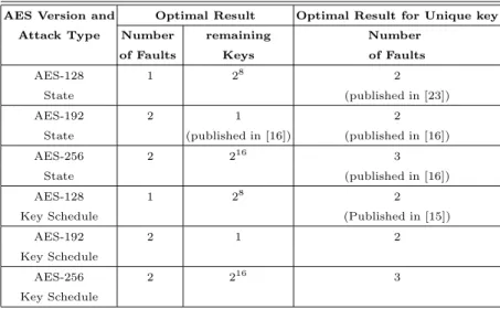
Table 1 shows the optimum results for the above two scenarios. The table also shows that in case of second scenario the existing attack on 128, AES-192, AES-256 states and AES-128 key schedule are optimal. In rest of the cases, there is no reported DFA attack which reached the optimum limits. Therefore, the table shows that there is a scope of work in this area which is the motivation behind this paper.
In the next two sections we present differential fault analysis against the AES state matrix and key schedule respectively. We show that our attack on the AES state matrix has reached its theoretical limits. However, in the case of DFA on the AES key schedule the limit has not yet been reached. Only, the DFA on AES-128 key schedule has reached to its limits. The proposed DFA on AES-192 and AES-256 key schedule are very close to their limits.
We start with the DFA on the states of three version of AES.
5
Basic Principle of DFA on AES
Table 1.Optimal Limits of DFA on AES
AES Version and Optimal Result Optimal Result for Unique key
Attack Type Number remaining Number
of Faults Keys of Faults
AES-128 1 28 2
State (published in [23])
AES-192 2 1 2
State (published in [16]) (published in [16])
AES-256 2 216 3
State (published in [16])
AES-128 1 28 2
Key Schedule (Published in [15])
AES-192 2 1 2
Key Schedule
AES-256 2 216 3
Key Schedule
Table 2.Optimal Limits of Diagonal Attacks on AES
No. of 1-Diagonal DFA 2-Diagonal DFA 3-Diagonal Faulty Bytes (M0) (M1) (M3)
Optimal Optimal Optimal
Result Result Result
1 28 28 28
2 216 216 216
3 224 224 224
4 232 232 232
5 − 240 240
6 − 248 248
7 − 256 256
8 − 264 264
9 − − 272
10 − − 280
11 − − 288
12 − − 296
following the differential characteristic she deduces some equations which relate the input-output difference of the S-boxes.
S
S
in⊕β
out out⊕α
K K
in
Fig. 4.Difference across S-box
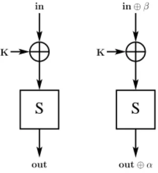
in is the previous round output byte andK is the round key byte. Due to the fault induction, a difference β is generated in X following which there is an output difference α at the S-box output out. Now if we replace the value of in⊕KbyX, we get following differential equation;
α=S(X⊕β)⊕S(X) (1)
According to the properties of AES S-box for a particular value ofαandβ the above equation can have 0, 2, or 4 solutions ofX [21]. For a fixed value ofβ, in 126 out of 256 choices ofαthe equation gives 2 solutions ofX, and in only one choice ofαthe equation gives 4 solutions and the rest of the choices ofαwill not give any solution for X. This implies only 127 out of 256 choices of αproduce solutions for X. For more details one can refer [21]. Therefore, if we know the values ofα, βandinwe can get the values ofK from the above equation.
Equation (1) is the basis to almost all the DFA attacks on SPN and Feistel ciphers. The attacker induces fault in such a way so that she can deduce equations like (1), which relates the round key bytes with the input-output difference. Then solving these equations she retrieves the round keys. Depending on the key schedule of the cipher she needs to retrieve sufficient number of round keys to get the master key.
5.1 First Phase of DFA on AES
In AES, if one byte difference is induced at the input of a round function, due to
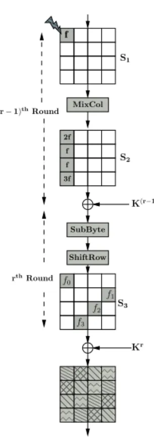
MixColumnsoperation the difference spread to four bytes at the round output. Fig. 5 shows one such scenario.
00 00 00 11 11 11 00 00 00 00 11 11 11 11 00 00 00 00 11 11 11 11 00 00 00 00 11 11 11 11 00 00 00 00 11 11 11 11 00 00 00 00 11 11 11 11 00 00 00 00 11 11 11 11 00 00 00 11 11 11 00 00 00 11 11 11 00 00 00 11 11 11 00 00 00 11 11 11 00 00 00 00 11 11 11 11 00 00 00 11 11 11 00 00 00 11 11 11 00 00 00 11 11 11 00 00 00 00 11 11 11 11 0 0 0 1 1 1 0 0 0 0 0 0 0 1 1 1 1 1 1 1 0 0 0 0 0 0 1 1 1 1 1 1 0 0 0 1 1 1 0 0 0 0 0 0 0 0 0 0 0 0 0 1 1 1 1 1 1 1 1 1 1 1 1 1 f 000 000 000 111 111 111 SubByte ShiftRow Kr f0 f2 f1 S3 f3
K(r−1)
S2 S1 MixCol f f 3f 2f (r−1)thRound
rthRound
Fig. 5.Differences across the Last Two Rounds
A single byte difference is generated before the (r−1)-th roundMixColumns
by the induced fault. The value of this difference isf and the corresponding 4-byte output difference is (2f, f, f,3f), where 2,1,and 3 are the elements of the first row of theM DS matrix used inMixColumnsoperation. The 4-byte differ-ence is again changed to (f0, f1, f2, f3) by ther-th round S-box. TheShiftRows
2f=S−1(C0,0⊕Kr0,0)⊕S −1
(C∗ 0,0⊕K
r
0,0) f=S−1(C1,3⊕Kr1,3)⊕S
−1
(C∗ 1,3⊕K
r
1,3) f=S−1(C2,2⊕Kr2,2)⊕S
−1
(C∗2,2⊕K
r
2,2)
3f=S−1(C3,1⊕Kr3,1)⊕S −1
(C∗ 3,1⊕K
r
3,1)
(2)
HereCandC∗are the fault-free and faulty ciphertexts. AES S-box is bijective, therefore each of the above four equations can be represented as equation (1). Again, equation 1 can be represented as:A=B⊕CwhereA, B, andCare bytes inF28, having 28possible values each. A random value of (A, B, C) satisfies this equation with probability 218. Therefore, 216 out of 224 choices of (A, B, C) will
satisfy the equation.
If we have M such equations which contain N variables in that case the reduce search space is given by (218)M ·(28)N = (28)N−M. In the above set of
four equations we have five unknown variables: f, K0r,0,K1r,3, K2r,2, and K3r,2.
Therefore, the four equations reduce the search space to (28)5−4 = 28. This
implies only 28 candidates of the quartet of key bytes will satisfy the above
four equations. By inducing two such faults one can uniquely determine the key quartet. In the same way one can also get the rest of the three quartets ofKr.
It may also be observed that if the location of the induced difference is changed then only the indices of the variables and the order of the equations will changed. The basic form of the equations will remain same.
OnceKr is determine the attacker applies the second phase of the attack to determineKr−1.
5.2 Second Phase of DFA on AES
In the second phase, the attacker induces faults in such a way so that a single byte difference is generated at the input of (r−2)-th round MixColumnsoperation. The fault propagation pattern remain same as in the first phase of the attack. Therefore, if the input difference isf′, then the 4-byte output difference of (r−
2)-th round is (2f′, f′, f′,3f′). These differences can also be represented by (r−
1)-th round fault-free and faulty outputs. However, due to 1)-the (r−1)-th round
MixColumnsoperation, the equations will change (the last round does not have
MixColumns). For example, 2f′ can be represented by following equation:
2f′=S−1(14(C0r,−10 ⊕K
r−1 0,0 )⊕11(C
r−1 1,0 ⊕K
r−1 1,0 )⊕
13(C2r,−10 ⊕K
r−1 2,0 )⊕9(C
r−1 3,0 ⊕K
r−1 3,0 ))⊕ S−1(14(C0∗(,0r−1)⊕Kr0,−10 )⊕11(C
∗(r−1) 1,0 ⊕K
r−1 1,0 )⊕
13(C2∗(,0r−1)⊕K
r−1 2,0 )⊕9(C
∗(r−1) 3,0 ⊕K
r−1 3,0 ))
(3)
HereCr−1andC∗(r−1)are the fault-free and faulty output of (r−1)-th round.
5.3 Similarity and Differences Between the Attacks
In the previous two sections we explain the basic principle of a DFA on AES. It uses simple divide and conquer approach. However, when we apply this technique to different versions of AES, the complexity of the attack changes drastically. For DFA on AES states, the first phase of the attack is same for all the three versions. It only retrieves the final round key. However, solving the second phase equations (Eq. (3)) are real challenge. As we can see each equation consists of four key bytes and these key bytes are not same across all the four equations generated from the 4-byte difference. If we consider all the four equations we have total seventeen unknown variables; sixteen bytes of Kr−1 and f. Therefore, it
is evident that the required exhaustive search on these variable is not practical. Therefore, the attacker must find some relation between these key bytes.
In order to do that the attacker takes the help of AES key schedule. As the key schedule is different for different versions of AES, therefore the attack strategy will also be different. Further, attacking AES key schedule is much more difficult than attacking AES state. In the first case the number of variables in the first phase and the second phase equations are more due to the diffusion of the differences in the key schedule.
6
DFA on AES State
In this section, we propose optimal DFA attacks on the AES state. The present section presents differential fault attacks on AES-128 and AES-256, and shows how an optimal fault attack can be performed. As proved in Section 4, a single byte fault can reveal 120 bits of information of the AES key. Hence, an optimal DFA on AES-128 would require a single fault (as the remaining uncertainty of 8 bits can be obtained using a practical exhaustive search). However for AES-256, an optimal DFA should need two faults, as then the remaining uncertainty is of (256−2·120) = 16 bits, which also can be easily computed through a brute force analysis. In the following description, we present the attack steps which reach these optimal limits. It may be pointed out that for AES-192, the attack proposed in [16] already reaches the optimal limit.
6.1 DFA on AES-128 State
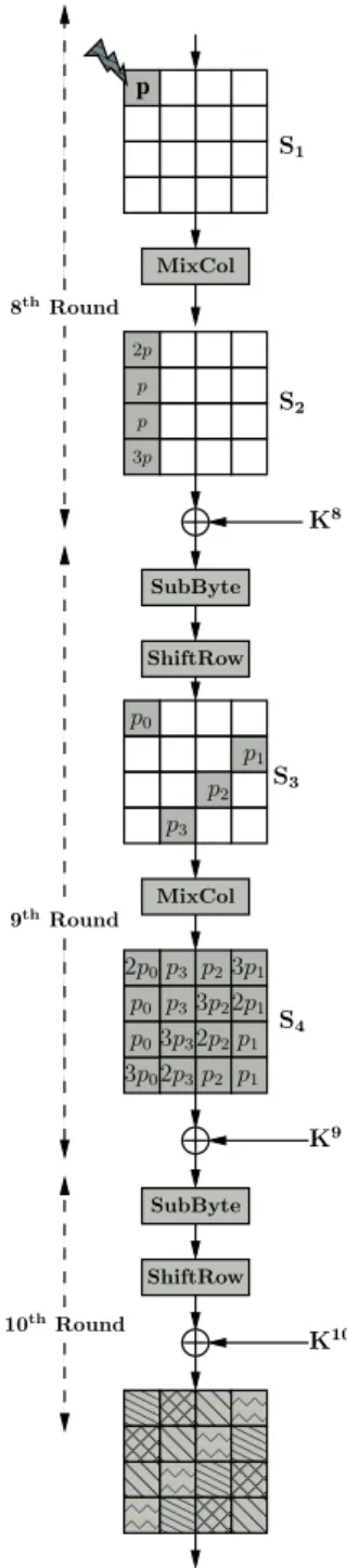
In these section we propose a two phase attack on the AES-128 state matrix by inducing a single byte fault in between the seventh and eighth roundMixColumns
operations. In the first phase of the attack we reduce the search space of the final round keyK10 to 232hypotheses using the differential equations at the output
First Phase of the Attack on AES-128 State A single byte random fault is induced in between the seventh and eighth roundMixColumnsoperations. Fig. 6 shows the flow of such a fault. The induced fault is propagated from the output of the eighth round
MixColumns operation to the first column of S2 and subsequently to all the
volumes of the state matrix after the ninth roundMixColumnsoperation. This actually serves the objective of inducing four faults at four different columns of the state matrix input to the ninth round MixColumnswhich is described in Section 5.1.
Therefore, the difference between columns of state matrices in the fault-free and faulty ciphertexts can be expressed in terms of these ciphertexts and the tenth round keyK10. The first column ofS
4will produce four equations similar
to equations (2). In this caser will be replaced by 10 and the 4-byte difference (2f, f, f,3f) will be replaced by (2p0, p0, p0,3p0). We call this equations as
ninth round differential equations. These equations will reduce the search space of key quartet (K10
0,0,K110,3, K210,2, K310,2) to an expected value of 28.
Similarly, we can deduce three sets of equations from the rest of the three columns of the state matrix S4. These three sets of equations will reduce the
corresponding quartet of key byte’s search space to 28hypotheses. If we combine
all the four key quartets, we get (28)4= 232 hypotheses ofK10. So, in the first
phase of the attack we have 232 hypotheses forK10. In the second phase of the
attack we further reduce the search space of K10.
Second Phase of the Attack on AES-128 State In order to further reduce the search space of the final round key we consider the relationship between the faulty bytes at the first column of S2, see Fig. 6. In order to do that we need
K9and the ninth round fault-free and faulty outputs (C9, C∗9). However, as the AES-128 key schedule is invertible, therefore, we can avoid making hypotheses directly onK9 by performing inverse key schedule operation as:
(K100,0⊕S[K101,3⊕K110,2 ] K010,1⊕K010,0K010,2⊕K010,1K010,3⊕K010,2
⊕h10 )
(K101,0⊕S[K102,3⊕K210,2 ])K110,1⊕K110,0K110,2⊕K110,1K110,3⊕K110,2
(K102,0⊕S[K103,3⊕K310,2 ])K210,1⊕K210,0K210,2⊕K210,1K210,3⊕K210,2
(K103,0⊕S[K100,3⊕K010,2 ])K310,1⊕K310,0K310,2⊕K310,1K310,3⊕K310,2
.
In order to get (C9, C∗9) we do one round decryption operation on (C, C∗) using the hypotheses forK10.
The 4-byte fault value (2p, p, p,3p) at the first column of S2 can be
rep-resented in terms of (C9, C∗9) and K9 which in turn produces four equations similar to equation (3). In that case the value of r will be replaced by 9 and (2f′, f′, f′,3f′) will be replaced by (2p, p, p,3p). We call these equations as eighth round differential equations. In these four differential equations, we have 232hypotheses for (K9, C9, C∗9) and 28possible values forp. Therefore, the four
equations reduce the search space to (2(2328·)248) = 28, i.e. from the 232 hypotheses
forK10only 28will satisfy the set of four equations. This result shows that our
000 000 000 111 111 111 000 000 000 000 111 111 111 111 000 000 000 111 111 111 00 00 00 00 11 11 11 11 00 00 00 00 11 11 11 11 000 000 000 111 111 111 000 000 000 111 111 111 000 000 000 111 111 111 000 000 000 111 111 111 00 00 11 11 00 00 11 11 00 00 00 00 11 11 11 11 00 00 00 11 11 11 00 00 11 11 000 000 111 111 00 00 00 11 11 11 0 0 0 1 1 1 0 0 0 0 0 0 0 0 0 1 1 1 1 1 1 1 1 1 0 0 0 0 0 0 0 0 1 1 1 1 1 1 1 1 0 0 1 1 0 0 1 1 0 0 0 0 0 0 0 0 0 0 0 0 0 1 1 1 1 1 1 1 1 1 1 1 1 1 0 0 0 0 0 0 0 0 0 0 0 0 0 0 0 0 0 0 0 0 0 0 0 1 1 1 1 1 1 1 1 1 1 1 1 1 1 1 1 1 1 1 1 1 1 1 0 0 0 0 0 1 1 1 1 1 0 0 0 0 1 1 1 1 p 000 000 000 111 111 111 SubByte ShiftRow MixCol K10 2p p p 3p p2 p1 p3 p0
8thRound
MixCol
2p0
p0
2p3 p3
3p2 2p2
p2
3p1
2p1 p1
p1
p3
p03p3
3p0 p2
K8
S3
K9
9thRound
10thRound
S4
S2
S1
SubByte
ShiftRow
However, the time complexity of the attack is still 232, as each of the 232
choices ofK10are tested by set of four equations. In the next section we propose
an acceleration technique by which the attack time complexity reduces to 230 from 232.
Reducing the Time Complexity of the Attack In order to reduce the time complexity of the attack we observe the basic properties of the differential equations as explained in Section 5.
If we consider the ninth round differential equations in the first phase of the attack, each of which can be represented as equation (1). In that case p0 corresponds to α. Therefore, if a value p0 contributes to the solutions of
(K010,0, K110,3, K210,2, K310,1), then there will total 24 solutions of the quartet for one
such choice of p0 as each of the key bytes will have 2 solutions4. For
exam-ple if (a0, b0, c0, d0) is one solution of the quartet then there is another solution
(a1, b0, c0, d0) whereK010,0has the second solutiona1, whereas the rest of the three
key bytes have the same values. This implies if we only want the unique choices of the last three key bytes among all possible solutions of (K010,0, K110,3, K210,2, K310,1),
we get 228 = 27choices.
Now in the eighth round differential, each byte ofC9 orC∗9 consists of one
byte of tenth round key. For example C9
0,0 consists of key byte K010,0. However,
in case of ninth round key byte, if the key byte is in the first column of K9, it
requires three byte of K10 whereas for the other key bytes of K9 requires two
bytes of K10. Therefore, if we consider these equations in pairs, all the pairs of
equations does not consists of same number of key bytes of K10. The pair of equations which consists of second and third equations requires least number of key bytes 14 (except the key bytesK010,0 andK010,1).
Therefore, in order to reduce the time complexity of the attack, in the second phase we test the second and third equation first by the unique choices of 14 key bytes ofK10 (excluding key bytesK010,0 and K010,1 ). There are total 232 choices
ofK10out of which the number unique choices of required 14 key bytes is given by 22322 = 230. Therefore, out of these choices only
230
28 = 222 will satisfy the two
equations. Rest will be discarded. Those which satisfy are combined with the 22 choices of the rest of the two key bytes and further tested by the other two
eighth round differential equations.
As we need to test only 230times in the second phase of the attack, therefore,
the time complexity of the attack reduces to 230 from 232. The summary of the
proposed attack is presented in Algorithm 2.
6.2 DFA on AES-192 States
A DFA on AES-192 has been proposed by Kim [16] which exploits all the avail-able information. According to our analysis a single byte fault should reveal 120-bit of the secret key. AES-192 has a 192-bit key, and therefore one would
4
Algorithm 2:DFA on AES-128 State
Input: C, C∗
Output: ListLkof tenth round keyK10
Solve the four sets of equations ofS4(Fig. 6) independently.
Get 232hypotheses ofK10. for Each candidates ofK10do
GetK9fromK10using AES-128 Key Scheduling.
Get unique choices of 14 bytes ofK10exceptK010,0, K 10 0,1.
Test the 2ndand 3rdequations ofS
2 if Satisfiedthen
forEach candidates of(K10
0,0, K010,1)do
Test the 1stand 4thequations ofS
2. ifSatisfiedthen
SaveK10toLk.
end end end end
returnLk
expect the most efficient attack would need two single byte faults. Kim’s attack required two faults and uniquely determines the key.
6.3 DFA on AES-256 States
In this section we propose a two phase DFA on AES-256 states and show that our attack reaches its limit as per the analysis in Section 4. The analysis says that using a single byte fault induction one can reveal maximum of 120 bits of the secret key. AES-256 has a 256-bit key. Therefore, two fault induction should be able to reveal (120·2) = 240 bits of the key.
According to the AES-256 key schedule, retrieving one round key is not enough to get the master key. Algorithm 1 shows that the penultimate round key is not directly related to the final round key. Therefore, the attack on AES-128 cannot be directly applicable to AES-256.
We propose an attack which requires two faulty ciphertextsC1∗andC2∗and a fault free ciphertextC. The first faulty ciphertextC1∗is generated by inducing a single byte fault between theMixColumnsoperations in the eleventh and twelfth round, whereas C2∗ is generated by inducing a singe byte fault in between the
MixColumns operations in the tenth and eleventh round. Fig. 7(a) shows the flow of faults corresponding to C1∗ whereas Fig. 7(b) shows the flow of faults
corresponding toC2∗.
The proposed attack works in two phases. In the first phase of the attack we reduce the possible choices of final round key to 216 hypotheses and in the
second phase of the attack we deduce 216 hypotheses for the penultimate round
00 00 11 11 00 00 00 00 11 11 11 11 00 00 00 11 11 11 000 000 000 111 111 111 000 000 000 000 111 111 111 111 00 00 00 11 11 11 00 00 00 11 11 11 00 00 11 11 00 00 00 11 11 11 000 000 111 111 000 000 111 111 000 000 000 111 111 111 000 000 000 111 111 111 000 000 111 111 00 00 11 11 000 000 000 111 111 111 0 0 0 0 0 0 0 0 0 1 1 1 1 1 1 1 1 1 0 0 0 0 0 0 0 1 1 1 1 1 1 1 0 0 0 1 1 1 0 0 1 1 0 0 0 0 0 0 0 0 0 0 0 0 0 1 1 1 1 1 1 1 1 1 1 1 1 1 0 0 0 0 0 0 0 0 0 0 0 0 0 0 0 0 0 0 0 0 0 0 0 0 1 1 1 1 1 1 1 1 1 1 1 1 1 1 1 1 1 1 1 1 1 1 1 1 0 0 0 0 0 1 1 1 1 1 0 0 0 0 1 1 1 1 0 0 0 1 1 1 p 00 00 00 00 11 11 11 11 2p p p 3p SubByte ShiftRow MixCol 12thRound
MixCol
p0
p2
2p0 p0
2p3 p3
3p2
2p2 p2
p1
3p1
2p1 p1 p1 p3 p03p3
3p0 p2
S3
K13
13thRound
14thRound
S4 S2 S1 SubByte ShiftRow X K12 K14 p3
(a) Flow of faults in the last three rounds of AES-256
0 0 1 1 00 00 00 00 11 11 11 11 00 00 00 00 11 11 11 11 00 00 00 11 11 11 000 000 000 000 111 111 111 111 000 000 000 000 111 111 111 111 00 00 00 11 11 11 00 00 00 00 11 11 11 11 00 00 00 00 11 11 11 11 00 00 00 00 11 11 11 11 000 000 000 111 111 111 000 000 000 000 111 111 111 111 000 000 000 000 111 111 111 111 000 000 000 000 111 111 111 111 000 000 000 111 111 111 00 00 00 00 11 11 11 11 000 000 000 000 111 111 111 111 0 0 0 0 0 0 0 0 0 1 1 1 1 1 1 1 1 1 0 0 0 0 0 0 0 0 0 0 0 0 0 1 1 1 1 1 1 1 1 1 1 1 1 1 0 0 0 1 1 1 0 0 1 1 0 0 0 0 0 0 0 0 0 0 0 1 1 1 1 1 1 1 1 1 1 1 0 0 0 0 0 0 0 0 0 0 0 0 0 0 0 1 1 1 1 1 1 1 1 1 1 1 1 1 1 1 0 0 0 0 0 0 0 1 1 1 1 1 1 1 0 0 0 0 0 0 0 0 0 1 1 1 1 1 1 1 1 1 0 0 0 0 0 0 1 1 1 1 1 1 0 0 0 0 0 0 0 0 1 1 1 1 1 1 1 1 p’ 00 00 00 00 11 11 11 11 SubByte ShiftRow MixCol SubByte ShiftRow MixCol ShiftRow 11thRound
S2 S1 K11 MixCol p’ p’ 3p’ 2p’ K12 X K13 K14 SubByte 12thRound
13thRound
14thRound 3p′
1
2p′
1S
3 2p′
0 p′
0
2p′
3 p′
3
3p′
2
2p′
2 p′ 2 p′ 1 p′ 1 p′ 3 p′
03p′3
3p′
0 p′
2
(b) Flow of faults in the last four rounds of AES-256
Fig. 7.Flow of Faults
First Phase of the Attack on AES-256 States In order to get the final round key we directly apply the first phase of the DFA on AES-128, described in Section 6.1, to the faulty ciphertextC1∗ (Fig. 7(a)). Therefore, using the relation between the faulty bytes in state matrixS4we reduce the possible values of the
final round key K14 to 232 hypotheses. Next we consider the second faulty
the faulty bytes that is similar to the state matrix S4of C1 (Fig. 7(a)). We
de-fineX as the output of the 13-th roundSubBytesoperation in the computation that produced the fault-free ciphertext. We also defineρandεas the differences at the output of 13-th round SubBytesoperation corresponding to two faulty ciphertextsC1∗ andC2∗ respectively. These two differences can be expressed as:
ρ=SR−1MC−1 SR−1(SB−1(C⊕K14) ⊕
SR−1(SB−1(C∗ 1⊕K
14
))
ε=SR−1MC−1 SR−1(SB−1(C⊕K14))⊕
SR−1(SB−1(C∗2⊕K 14
))
Therefore, the fault values in the first column ofS3(Fig. 7(b)) can be represented
in terms of X and ε by four equations similar to equation (1). In that case ε0,0, ε1,0, ε2,0, andε3,0are the values correspondingβ and 2p′0, p′0, p′0,and 3p′0
are the values corresponding to αin the four equations respectively.
Similarly, from the first column of state matrixS2 of Fig. 7(a), we get four
more differential equations which correspond to the first column of X and ρ. Therefore, corresponding to first column of X, we get two sets of differential equations. Again each byte of ε andρ corresponds to one quartet of K14. For exampleρ0,0 can be expressed as:
ρ0,0= 14(SB−1(C0,0⊕K014,0)⊕SB −1
(C∗ 1(0,0)⊕K
14 0,0))⊕
11(SB−1(C1,3⊕K141,3)⊕SB −1
(C1(1∗ ,3)⊕K 14 1,3))⊕
13(SB−1(C2,2⊕K142,2)⊕SB −1
(C1(2∗ ,2)⊕K 14 2,2))⊕
9(SB−1(C3,1⊕K143,1)⊕SB −1
(C1(3∗ ,1)⊕K 14 3,1))
(4)
We already know that each of the quartets are independently calculated and pro-duces 28hypotheses. Therefore, the four pairs (ε
0,0, ρ0,0), (ε1,0, ρ1,0), (ε2,0, ρ2,0),
and (ε3,0, ρ3,0) correspond to four quartets ofK14and each having 28values.
In order to solve two sets of differential equations of first column ofX, with minimum time complexity, we consider them in pairs. First we choose two equa-tions, for example from the second set we choose equations corresponding toX0,0
and X1,0. We guess the values ofp corresponding to each choice of (ρ0,0, ρ1,0)
and derive the possible values ofX0,0, X1,0, ε0,0, andε1,0. We test these values by
the corresponding equations in the first set. If they satisfy the relationships they are accepted, otherwise they are rejected. It may be observed that the mapping between a byte ofρand the corresponding byte ofε is one-to-one, as both the bytes are derived from same key quartet.
Therefore, in the two equations of the second set we guess 28·28·28= 224
hypotheses for (ρ0,0, ρ1,0, p) which is reduced to 216 hypotheses by
correspond-ing two equations of the first set. Each of these 216 hypotheses are combined
with 28 hypotheses for ρ
2,0 in the third equation of the second set and tested
by the corresponding equation in the first set. Again, the possible hypotheses reduce to 216. Then these values are combined with 28hypotheses forρ
3,0in the
216. Therefore, finally we will have 216 hypotheses forK14 each corresponding
to one value for (X0,0, X1,0, X2,0, X3,0). Throughout the process the time
con-suming part of the calculation is where 224 hypotheses are made and the rest is negligible. We, therefore, consider the time complexity of this process to be 224.
It can also be explained in straightforward way. There are eight equations, in whichp, p′
0, (X0,0, X1,0, X2,0, X3,0) andK14are unknown. The total search space
of these variables would be 280. Therefore, the reduced search space produced
by these eight equations is 280
(28)8 = 216.
In the second phase of the attack we deduce the values of penultimate round keyK13corresponding to 216choices ofK14.
Second Phase of the Attack on AES-256 States In order to get the penul-timate round key, we consider the last three columns ofS3in Fig. 7(b). For, one
choice ofK14, the differential equations from the last three columns ofS4will
re-duce the number of hypotheses for (X0,1, X1,1, X2,1, X3,1), (X0,2, X1,2, X2,2, X3,2),
and (X0,3, X1,3, X2,3, X3,3) to 28for each set. Then we get the last three columns
ofK12 fromK14as K12
i,j=Ki,j14⊕Ki,j−14 1, where 0≤i≤3 and 1≤j≤3.
Now from the first column ofS2 we get four differential equations similar to
equations (3). In this caseris replaced by 13. The twelfth round fault-free output can be expressed asC12=S−1(X). Similarly, the faulty outputs corresponding to two faulty ciphertexts can be expressed as C1∗12 =S−1(X⊕ρ) andC2∗12 =
S−1(X⊕ε).
Therefore, each of the four equations requires one column ofX and one col-umn ofK12. The last three equations can be directly solved as we already know the values of the last three columns ofX andK12. In order to reduce the time complexity we conduct a pairwise analysis. We first choose the second and third equations which correspond to (X0,3, X1,3, X2,3, X3,3) and (X0,2, X1,2, X2,2, X3,2).
We have 28hypotheses for both (X
0,3, X1,3, X2,3, X3,3) and (X0,2, X1,2, X2,2, X3,2).
Each of these hypotheses can be evaluated using these two equations that will reduce the value to 28choices. Those which satisfy these equations are combined
with the 28choices for (X
0,1,X1,1,X2,1,X3,1) and further tested by fourth
equa-tion which will again reduce the combined hypotheses of the last three columns ofX to 28possibilities. The values of (X
0,0, X1,0, X2,0, X3,0) are already reduced
to one possibility for a particular value of K14 in the first phase of the attack.
Therefore, this results in 28hypotheses for X. For each of these hypotheses we
get the first column ofK12 and test using the first equation. This will further reduce the hypotheses forX to 1. The time complexity here is around 216as we
consider two columns ofX at a time.
Therefore, one hypothesis for K14 will produce one value for X which in
turn produces one value forK13 by the following:K13 =M C(SR(X))⊕C13,
where C13 is the output from the 13-th round, which is known to the attacker
from the ciphertextCandK14previously ascertained. Hence one hypothesis for K14 will produce one hypothesis forK13. Therefore, the 216hypotheses ofK14
will produce 216 hypotheses for K13. In which case the total time complexity
corresponds to 216hypotheses for the 256-bit master key. According the analysis
in Section 4, two faulty ciphertexts should reveal 240-bit of the AES-256 key. Therefore, we can say that the proposed attack on AES-256 has reached its limit. The summary of the attack is presented in Algorithm 3.
Algorithm 3:DFA on AES-256 State
Input: C, C∗ 1, C2∗
Output: List of 256-bit keyLk
/*Xi,j=hX0,j, X1,j, X2,j, X3,ji*/
/*K12
i,j=hK
12 0,j, K
12 1,j, K
12 2,j, K
12 3,ji*/
Solve four sets of equations ofS4(Fig. 7(a)) independently.
Get 232hypotheses forK14.
Solve the two set of equations ofXi,0.
Get 216hypotheses forK14.
for each candidate ofK14do
Guess the possible candidates ofXi,1,Xi,2, andXi,3
Get the values ofK12
i,1,K12i,2, andKi,123fromK14 forEach candidate ofXi,3,Xi,2,Xi,1do
Test second, third and fourth equations ofS2(Fig. 7(b)) ifSatisfiedthen
GetKi,120fromK 14
andX
Test First equation ofS2(Fig. 7(b)) ifSatisfiedthen
GetK13fromX
Get 256-bit key from AES-256 Key Scheduling algorithm save the 256-bit key toLk
end end end end
returnLk
7
Attacks on AES Key Schedule
In the previous section we explained how a single byte difference induced at the state of a particular round can be exploited to reveal the secret key. Therefore, in order to protect AES from such attacks a designer has to use some countermea-sures which will not allow the attacker to induce fault in AES round operations. The DFA on AES key schedule is such kind of attack which works even if the rounds of the AES are protected against faults. In this case the fault is induced at the round key. Therefore, the normal countermeasures which only protect the round operations, will not be able to distinguish between a fault-free round key and a faulty round key. Hence, it will fail.
as subsequent round key because of which the differential equations are more complex than the DFA on AES states.
In this section, we present DFA on the AES Key Schedule for all the three versions of AES. The current section develops the attacks published in literature requiring 2 faults for AES-128, 16 faults for AES-192 and AES-256. The attacks proposed in this section requires 1 fault for AES-128, 2 faults for AES-192 and 3 faults for AES-256. Thus compared to the optimal attacks as shown in Section 4, we reach the limits for AES-128. However for AES-192 and AES-256 the present attack is much closer to the optimal results than that in the literature.
7.1 Attack on AES-128 Key Schedule
In this section we propose a two phase attack which will reduce the AES-128 key space to 28hypotheses using only one faulty ciphertext. The required faulty
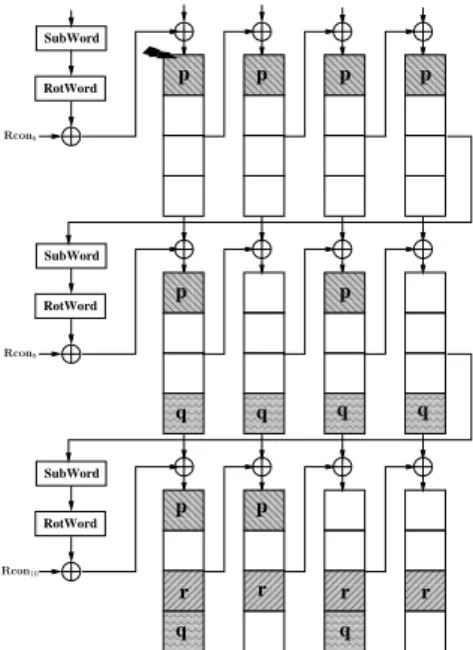
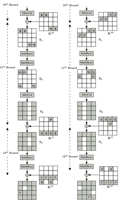
ciphertext is generated by inducing a single-byte fault in the first column of the eighth round key while it is being generated. Therefore, the induced byte fault is then propagated to subsequent round keys. Fig. 8 shows the flow of this fault as per the AES-128 key schedule. These faulty round keys subsequently corrupt the AES state matrix during the encryption process. The flow of faults in the AES states is shown in Fig. 9.
0000 0000 0000 0000 0000 0000 0000 1111 1111 1111 1111 1111 1111 1111 0000 0000 0000 0000 0000 0000 0000 1111 1111 1111 1111 1111 1111 1111 0000 0000 0000 0000 0000 0000 1111 1111 1111 1111 1111 1111 0000 0000 0000 0000 0000 0000 1111 1111 1111 1111 1111 1111 000 000 000 000 000 000 111 111 111 111 111 111 0000 0000 0000 0000 0000 0000 1111 1111 1111 1111 1111 1111 0000 0000 0000 1111 1111 1111 000 000 000 111 111 111 0000 0000 0000 1111 1111 1111 0000 0000 0000 1111 1111 1111 000 000 000 111 111 111 0000 0000 0000 1111 1111 1111 0000 0000 0000 0000 1111 1111 1111 1111 0000 0000 0000 0000 1111 1111 1111 1111 0000 0000 0000 1111 1111 1111 0000 0000 0000 1111 1111 1111 000 000 000 111 111 111 0000 0000 0000 1111 1111 1111 000 000 111 111 SubWord RotWord SubWord RotWord SubWord
RotWord p p p p
p p
p p
q q q q
r r r
q q
r Rcon10
Rcon9
Rcon8
00 00 00 00 11 11 11 11 0000 0000 0000 1111 1111 1111 0000 0000 0000 1111 1111 1111 000 000 111 111 0000 0000 1111 1111 0000 0000 1111 1111 000 000 111 111 000 000 000 111 111 111 000 000 000 111 111 111 0000 0000 0000 1111 1111 1111 000 000 000 111 111 111 000 000 000 111 111 111 0000 0000 0000 1111 1111 1111 0000 0000 1111 1111 000 000 111 111 000 000 111 111 0000 0000 1111 1111 0000 0000 0000 1111 1111 1111 0000 0000 0000 1111 1111 1111 000 000 111 111 0000 0000 1111 1111 0000 0000 0000 1111 1111 1111 000 000 000 111 111 111 000 000 000 111 111 111 000 000 000 111 111 111 0000 0000 0000 1111 1111 1111 000 000 000 111 111 111 000 000 000 111 111 111 0000 0000 0000 1111 1111 1111 0000 0000 1111 1111 000 000 111 111 000 000 000 111 111 111 0000 0000 0000 1111 1111 1111 0 0 0 0 0 0 0 0 0 0 0 1 1 1 1 1 1 1 1 1 1 1 0 0 0 0 0 0 0 0 0 0 1 1 1 1 1 1 1 1 1 1 0 0 1 1 0 0 0 0 0 0 0 0 0 0 0 1 1 1 1 1 1 1 1 1 1 1 0 0 0 0 0 0 0 1 1 1 1 1 1 1 0 1 0000000 1111111 0 0 0 1 1 1 0 0 1 1 0 0 1 1 000 000 000 000 111 111 111 111 000 000 111 111 000 000 111 111 000 000 000 000 111 111 111 111 00 00 00 00 11 11 11 11 00 00 00 11 11 11 00 00 00 11 11 11
0
0
1
1
00 00 00 11 11 11 00 00 00 11 11 11 00 00 00 11 11 110
0
1
1
000 000 000 000 111 111 111 111 000 000 000 000 111 111 111 111 000 000 000 111 111 111 000 000 000 111 111 111p p p p
p p p p
p p
q q q q
q q p p
r r r r
SubByte
ShiftRow
MixCol
K8(Faulty)
SubByte
ShiftRow
K9(Faulty)
K10(Faulty)
8thRound
9thRound
10thRound
S4 S5 S1 S2 2p0 p0 p0 3p0 2p1 p1 p1 3p1 p2 3p2 2p2 p2 2p3 p3 p3 3p3 S3
Fig. 9.Flow of faults in the last three rounds of AES-128
In the first phase of the attack we reduce the search space of the final round key to 240 hypotheses. In the second phase we further reduce this search space
First Phase of the Attack on AES-128 Key Schedule The faulty eighth round key corrupts the AES state matrix during the AddRoundKey operation. Fig. 9 shows that the faults in K8 corrupts the first row of the state matrix at the input of ninth round. Subsequently, the faults are propagated to all 16 bytes in the MixColumns operation. The faulty bytes in state matrix S2 can
be represented by the fault-free and faulty ciphertexts C and C∗. The first column S2 will produce a set of four differential equations similar to
equa-tions (2) which corresponds to the key quartet (K010,0, K110,3,K210,2,K310,1). Similarly,
from other three columns we get three more sets of equations corresponding to key quartets (K010,1,K110,0, K210,3, K310,2), (K010,2, K110,1, K210,0, K310,3), (K010,3, K110,2, K210,1,
K310,0). We refer to these four key quartets asKq0,Kq1,Kq2, andKq3respectively.
It may be observed that unlike the proposed DFA on AES-128, here the number of unknown variable are more. We have p, q, and r as extra unknown variables. Therefore, existing solving techniques will not be applicable to these equations. It may be noted that these three unknown variables are derived from key schedule operation and related by following equations:
q=S[K80,3]⊕S[K 8 0,3⊕p]
=S[K90,3⊕K 9 0,2]⊕S[K
9 0,3⊕K
9
0,2⊕p] (5)
=S[K100,3⊕K 10 0,1]⊕S[K
10 0,3⊕K
10 0,1⊕p] r=S[K93,3]⊕S[K
9 3,3⊕q]
=S[K103,3⊕K 10 3,2]⊕S[K
10 3,3⊕K
10
3,2⊕q] (6)
In the first three sets of equations there are 8 unknown variables (p, q, r, pi)
and the corresponding quartet of key bytesKqi; whereicorresponds to thei-th
quartet. We observe that the fourth set of equations does not containp. In order to get the quartetsKq0, Kq1, Kq2 from the first three sets of equations, we need
to test all possible 232 values for (p, q, r, p
i). For, each of these hypotheses we
get one hypothesis for Kq0, Kq1, and Kq2 each. Therefore, for all possible 232
choices we get 232hypotheses of each of the quartets. In the last set of equations
we have only q, r, and p3. Therefore, in the last set of equations we get 224
possible hypotheses forKq3. Hence, all the possible choices ofK10are given by
(232)3·224= 2120 which is not practical.
In order to solve the individual set of equations in practical time we apply a divide-and-conquer technique. We observe that the key bytesK010,3,K010,1, K310,2, K310,3,
and (p, q) are also contained in (5) and (6). Therefore, we can combine these equations with the last three sets of equation corresponding to Kq1, Kq2, and
Kq3. This will reduce the possible choices for the corresponding 12 key bytes.
In the first step we test the possible values of (p, q) For, each of these values we guess the 28 values of p
1 in the second set of equations. For each
(p, q, p1) we get the values of three key bytesK010,1, K110,0,andK310,2from the
cor-responding equations. Therefore, for one value of (p, q) we get 28hypotheses for
(K010,1, K110,0, K310,2). Similarly, we guess p3 in fourth set of equations and get 28
a total of 28·28 = 216 hypotheses for six key bytes (K10
0,1,K110,0,K310,2,K010,3,K110,2,
K10
3,0). These values are tested by using (5), which will reduce the possible values
of these six key bytes to 216
28 = 28hypotheses.
In the second step, for each hypothesis for the six key bytes, we guess the values ofp2 and get the three key bytes (K010,2, K110,1, K310,3) from the third set of
equations. Therefore, we have a total of 28·28 = 216 hypotheses for nine key
bytes (K010,1,K110,0,K310,2,K010,3,K110,2, K310,0, K010,2, K110,1,K310,3). We use these and get
the corresponding values ofrfrom (6). Therefore, now using the values ofrwe can deduce the other three key bytes (K210,3, K210,0, K210,1) from the corresponding
equations in the last three sets of equations. So, in the second step we deduce 216hypotheses for twelve key bytes from the last three sets of equations.
In the third step we test the 28values forp
0and get the corresponding choices
of the four key bytes {K010,0,K110,3, K210,2, K310,1} from the first set of equations.
Therefore, in the third step we deduce a total of 216·28=224hypotheses for the
16 key bytes ofK16corresponding to one hypothesis for (p, q). Therefore, for all possible 216 hypotheses for (p, q), we will get 224·216= 240hypotheses forK40.
However, the complexity of this attack is still quite high. In our experiments we found out that for a desktop with anIntel CoreT M2Duoprocessor clocked at 3 GHz speed takes around two and half days to perform brute-force search of 240possible keys.
Second Phase of the Attack on AES-128 Key Schedule In this phase of the attack we deduce differential equations from the differences in the state matrixS1(Fig. 9). In the first row of the state matrix we have 4-byte differences
(p, p, p, p). The faulty byte pat the first column of the state matrix can be rep-resented as equation (3). In that caserwill be replaced by 10 andpcorresponds to 2f′. Similarly, we get three more equations from rest of the three faulty bytes ofS1.
However, due to faulty key, the right hand side of each equations will have p, q, andr. In the first phase of the attack we have already reducedp, q, r, and K10 to 240 choices. Using these values we can get the ninth round fault-free
and faulty outputs. As per the attack on the AES-128 key scheduling algorithm (Fig. 8), we can directly deduce the ninth round key from the tenth round key. Therefore, for each value ofK10we get the corresponding values ofK9 and can test it using the four equations. There are four equations and the total search space is 240. Therefore, the four equations reduce the search space to 240
(28)4 = 28.
Hence, in the second phase of the attack we have only 28 hypotheses forK10.
These can then be used to drive 28 hypotheses for the master key.
Though the final search space is 28, the time complexity of the attack is still
240 since the second phase of the attack still needs to test each of the 240 keys
generated from the first phase of the attack.
four sets of equations produce 240values of 16-byte keyK10. Each of these keys
are tested by four equations in the second phase of the attack. However, none of these equations require all 16 bytes of the key. For example, the first equations required K010,0, K110,3, K210,2, K310,1 and nine more key bytes corresponding to four ninth round key bytesK09,0, K19,0, K29,0,K39,0. Therefore, in the first equation we
need 13 bytes ofK13. Similarly, in the rest of the three equations, each requires ten bytes of K10. In the first phase of the attack we use (5) and (6) since their dependencies are between the key bytesK010,3,K010,1, andK310,3,K310,2.
Therefore, in order to reduce the time complexity of the attack in the second phase we only test one equation at a time. We start with the third equation, as it only requires eleven bytes of K10 (ten key bytes plus one for K010,3 since
it depends on K010,1 in (5)). Those which satisfy this equation are accepted and
combined with the other five key bytes, and are subsequently tested using rest of the three equations. Those which do not satisfy these equations are simply discarded.
It is clear from the analysis in Section 6.1 that the number of unique choices of the eleven key bytes required by the third equation is 22405 = 235. Therefore,
we need only to test 235 hypotheses out of the 240 possibilities for the 16-byte
key. Those which satisfy the test are combined with 25 possible hypotheses for
the remaining five key bytes and subsequently tested using rest of the three equations. The first test will reduce the possible hypotheses for 11 key bytes to 235
28 = 227. Therefore, the rest of the three equations are tested using the
227·25= 232 hypotheses for the 16-byte key, which will reduce the number of
hypotheses to (22328)3 = 28.
So, finally we get 28 hypotheses for K10, and we test a maximum of 235
hypotheses for the key. Therefore, the time complexity of the attack is reduced to 235from 240. This result also supports the analysis in Section 4, which states
that single fault should be able to reduce the number of key hypotheses for a AES-128 to 28. Therefore, we can claim that the proposed attack is also optimal
for a fault attack that analyzes the AES-128 key schedule. The proposed attack summary is presented in Algorithm 4.
7.2 Proposed Attack on AES-192 Key Schedule
In this section we propose an attack on AES-192 using only two faulty texts. The most recent attack to date requires around 4 to 6 faulty cipher-texts [15]. Due to the different key scheduling algorithm the attack described above for the AES-128 can not be directly applied to AES-192, since the knowl-edge of last round key is not sufficient to get the master key. From Algorithm 1 we know that the first two columns of the eleventh round key K11 can easily be retrieved from the first three columns of the twelfth round key K12 by fol-lowing simple XOR operations since:K11
i,j=Ki,j12⊕Ki,j−12 1 where 0≤i≤4 and