Transactions, SMiRT-25 Charlotte, NC, USA, August 4-9, 2019
Division III
SOIL-PILE-STRUCTURE INTERACTION ANALYSIS:
IMPLEMENTATION OF FLEXIBLE ALTERNATIVE THEORETICAL
APPROACH IN SASSI FRAMEWORK
Julio A. García1, Benjamin Kosbab2, Huy Tran3, Tobias Richter4, and Peter Rangelow5
1 Principal Engineer, SC Solutions, Marietta, GA, USA, [email protected] 2 Principal Engineer, SC Solutions, Marietta, GA, USA
3 Principal Engineer, SC Solutions, Seattle, WA, USA
4 Consultant, formerly Framatome now BHI Energy, San Jose, CA, USA 5 Senior Expert, Basler & Hofmann AG, Zürich, Switzerland
ABSTRACT
This paper introduces a new alternative for soil-pile-structure interaction analysis, based on established soil-pile interaction theory, which accommodates a wide range of foundation conditions. A description of the theoretical formulation and its implementation into the prevalent SASSI software framework via SC-SASSI (SC Solutions, 2018) is provided in this paper, including examples and usage recommendations. A companion paper (Rangelow et al, 2018) discusses benchmark results (impedance functions) of this implementation derived for various pile foundations.
A key component to solve the soil-structure interaction problems in the frequency domain (such as in the SASSI framework) is the compliance matrix. The traditional formulation for the compliance matrix implemented in SASSI (Lysmer et al., 1981) has proven to be effective for the simulation of shallow foundations, but it is found inadequate for simulation of pile foundations. An alternative formulation for the simulation of pile foundations builds the compliance matrix for the portion of the soil where piles are embedded using Green’s function formulations for ring and disk loads, which are semi-analytical formulations to calculate displacements both outside and inside of a cylindrical core. The Green’s functions are evaluated using the equivalent radius of the pile, considering a disk load distribution at the interaction node located at the pile tip, while ring load distributions are considered at the remaining interaction nodes along the pile shaft.
INTRODUCTION
Deep foundations (e.g. pile foundations) are often used for nuclear facilities in soft soil conditions in order to carry the structural loads to deep firm layers, e.g. nuclear power plants in Germany, the Netherlands, Belgium, Brazil and U.S.A. Due to relatively slender geometrical configurations and large number of piles, refined analysis of pile foundations is a challenging task that is typically beyond the scope of many generic soil-structure interaction analysis tools. This paper introduces a new alternative for soil-pile-structure interaction analysis, based on established soil-pile interaction theory, which accommodates a wide range of foundation conditions. A description of the theoretical formulation and its implementation into the prevalent SASSI software framework via SC-SASSI (SC Solutions, 2018) is provided in this paper, including examples and usage recommendations. A companion paper (Rangelow et al, 2018) discusses benchmark results (impedance functions) of this implementation derived for various pile foundations.
THEORY
The soil-pile interaction problem is considered as an extension of the soil-structure interaction problem and analyzed subdividing it into sub-systems (sub-structuring approach): (1) the pile (as part of the structure) and (2) the displaced soil are both described and formulated using the finite element method, and (3) the site is described and formulated in terms of a compliance matrix (soil flexibility matrix) using the flexible volume method.
Piles are simulated with pile elements, which are similar to the mechanical formulation of beam elements, but account for the effect of the displaced soil. Each pile element spans through one discrete soil layer and connects with the adjacent pile elements through interaction nodes defined along the pile axis.
A key component to solve soil-structure interaction problems in the frequency domain (such as in the SASSI framework) is the compliance matrix. To obtain the compliance matrix, the basic problem is to determine the displacement responses of all the interaction nodes subject to unit loads placed successively at one column of interaction nodes; once this problem has been solved, solutions corresponding to other interaction nodes are obtained by a shift of the horizontal coordinates.
The traditional formulation for the compliance matrix implemented in SASSI uses free field displacements resulting from concentrated unit loads (point loads) which are generated with a combination of transmitting boundaries (exact solution) for the far field, and a finite element formulation (discrete approximation) for the near field (Lysmer et al., 1981). This formulation has the shortcoming that it is not defined along the vertical line under the load, as the displacements at those locations for a concentrated load are infinite (singularity). The traditional formulation of the compliance matrix has proven to be effective for the simulation of shallow foundations, as these local effects below the loaded node are compensated amongst an array of additional nodes located along the same horizontal plane. However, the displacements from concentrated unit loads are inadequate particularly for a single pile, as only one single node is defined along a horizontal plane.
soil conditions; for modeling purposes, soft soil conditions imply a relatively high number of thin discrete layers to reach the depth of pile tip; in other words, pile foundation models can become computationally expensive as their typical size is dictated by the often high number of interaction nodes, which is a function of the number of discrete layers and of the number of piles. However, taking advantage of the high-performance computing (HPC) capabilities of SC-SASSI, the Green’s functions approach becomes more attractive for practical applications, as reasonable computational times are achievable even for large models, while the flexible and automated post-processing tools available in SC-SASSI also shorten the time and effort typically associated with large amounts of output data.
This study is developed to analyze combinations of pile foundations of different cross sections as well as with shallow foundations, to consider simultaneously pile-cap-soil as well as pile-soil-pile interaction effects. For a generic geometric configuration consisting of shallow foundations, and pile groups of two or more cross sections, the compliance matrix is partitioned according to the loaded node locations in each of the geometric zones: loaded nodes on the shallow foundations use a concentrated load for compliance definition; and piles of the same cross section use Green’s functions for circular loads (ring and disk loads) defined for the same radius as the actual (or equivalent) radius of the pile, to represent the load transmission mechanism from the pile to the soil.
Green’s Functions Approach
The load transmission to the soil is represented using Green’s functions (GF) for ring and disk loads (distributed loads), which defines the displacements outside and inside of the perimeter of the load. The GF approach uses an exact formulation to calculate displacements in the horizontal direction and therefore does not require a finite element formulation inside of the perimeter of the load.
This is an extended and alternative approach in comparison with the traditional approach that simulates the load transmission to the soil (concentrated loads) using transmitting boundaries (TB) in cylindrical coordinates to formulate the far field displacements (which is equivalent to the GF formulation for far field), while a coupled cylindrical finite element core is used to describe the near field displacements.
The approach to use GF is an extension of the work done by Waas and Hartmann (1981), Kaynia (1982), García (2002), amongst others. The GF formulation as published by Kausel & Peek (1982) is used in this study and restated here for completeness.
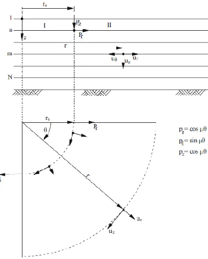
Considering a general ring force distribution of radius r0 acting in the radial, tangential or vertical direction on the boundary of layer n, as shown in Figure 1 and a discretization in the vertical direction, the displacements (GF) along the boundary of the layer m, at a horizontal distance r from the center of the load, are given by:
(1a)
(1b)
Where φx and φz are mode shapes for generalized Rayleigh waves in x and z direction, respectively,
φy are mode shapes in y direction for generalized Love waves, αR and αL are factors depending on the
orientation and geometric configuration of the load, and f are algebraic expressions function of the geometric position where displacements are calculated (inside or outside of the radius r0, indicated by regions I and II in Figure 1, respectively), of complex Hankel functions and complex Bessel functions, as well as of the wave number k. The displacement components are then transformed from cylindrical into Cartesian coordinates.
Figure 1: Ring Forces and Displacements over a Rigid Base.
Free Field Displacements
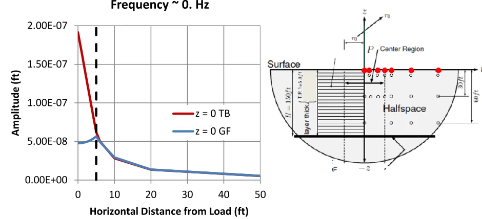
To evaluate the validity of the GF approach for distributed load to represent the soil flexibility for soil-pile simulation, free field displacements are calculated with the GF approach using unit distributed ring loads and compared with free field displacements calculated with the traditional TB approach using unit concentrated loads. The dynamic unit loads, characterized with a radius r0=5ft, are applied at the surface of a soil half-space, with shear wave velocity of 400 ft/s and material damping of 0.5%.
Figure 2 shows a comparison of horizontal free field static displacements calculated with the GF approach using horizontal unit distributed loads (ring loads) versus the TB approach using horizontal unit concentrated loads (point loads). The horizontal axis indicates the horizontal distance, measured from the center of the load, to the location where displacements are calculated. The vertical dashed line indicates the boundary of the load r0=5ft.
soil flexibility. This displacement comparison confirms the suitability of the GF approach over the TB approach to simulate pile foundations.
Figure 2: Horizontal Static Free Field Displacements at the Ground Surface due to Horizontal Unit Load Calculated with GF and TB.
Figure 3 shows the results for a node located at a distance of 10 times the radius of the load and at a depth of 30 ft from the ground surface (located at the red dot on the right-side sketch) comparing the displacement transfer function resulting from the GF approach using unit ring load vs. the transfer function resulting from the TB approach using unit point load.
Figure 3: Free Field Displacements Transfer Functions at a Horizontal Distance of 10*Radius and at a Depth of 30 ft Calculated with GF and with TB.
0.00E+00 5.00E-08 1.00E-07 1.50E-07 2.00E-07
0 10 20 30 40 50
Am
p
litu
d
e
(ft)
Horizontal Distance from Load (ft)
Frequency ~ 0. Hz
It is observed that at a certain distance and depth from the loaded area, the displacements calculated with the ring loads approach reasonably the displacements calculated with point loads, with small differences, mostly in relatively high frequency, due to the different behaviour between ring loads and point loads at that distance and depth. Thus, it has been verified that: (a) disk loads GF behaves physically consistent within the loaded area with the pile/soil load transfer mechanism; and (b) disk loads GF displacements approach the displacements calculated with point loads at certain distance and depth from the loaded area. Therefore, the ring/disk loads GF are selected and implemented in SC-SASSI to simulate soil-pile interaction.
Compliance Matrix
In order to simulate both shallow and/or pile foundations, two alternative approaches are used to evaluate the dynamic compliance (flexibility) matrix. The first one uses a model consisting of a cylindrical core that is connected to a TB and uses a finite element formulation inside of the core (concentrated load formulation). The second one uses GF consisting of an exact formulation to calculate displacements, both outside and inside of the core (distributed load formulation). The former is the traditional and preferred approach for shallow foundations, while the latter is required for pile foundations.
The soil impedance matrix is calculated as the inverse of the soil compliance matrix. The elements
fjk of the soil compliance matrix are determined by successively applying unit amplitude loads at each
degree of freedom k of the interaction nodes and computing the corresponding complex displacements (also known as compliances) at each degree of freedom j of the interaction nodes. For simulating pile foundations, GF of the layered media for the interaction nodes are used to calculate compliances.
To simulate the load transfer from the pile to the subsoil, the interaction nodes are selected along the pile axis. For piles, a disk load distribution of unit amplitude and radius equal to the pile radius is considered at the interaction node located at the pile tip, while ring load distributions of unit amplitude and radius equal to the pile radius are considered at the remaining interaction nodes (García, 2007).
IMPLEMENTATION
To enable the soil-pile-structure simulation with SC-SASSI, three key steps are implemented: (1) GF for ring and disk loads are first defined in POINT and then further used to compute the compliance matrix in ANALYS; (2) a pile-element is implemented to simulate both the structural pile model as well as the displaced soil model of the pile in HOUSE; and, (3) groups of interaction nodes are introduced and defined in HOUSE to identify how the corresponding portions of the compliance matrix should be calculated.
Ring and Disk Loads in SC-POINT
Ring and disk unit loads are defined in the program module POINT. Depending on the foundation geometry, three options are offered for the definition of unit loads at the layer interfaces to calculate the compliance matrix: (1) the traditional point loads, also referred as “traditional method”, which are solved through a finite element formulation attached to TB; this is the option for shallow foundations (generally speaking, any foundation type other than piles or caissons); (2) ring and disk loads, which are solved through GF formulation; this is the required option for pile foundations; and, (3) combination of traditional point loads (option 1) with ring and disk loads (option 2); this is the option for a combined foundation consisting, for example, of a basement (option 1) sitting on piles (option 2).
between a node located at the pile tip (where disk load are used) and a node located at the pile shaft (where ring loads are used) within each pile group; (2) off-diagonal compliance term between a node located between the two pile groups, where each pile group uses GF and unique pile radius; and (3) off-diagonal compliance term between a node located in any pile group assigned to use GF and a node located in the shallow foundation region, either attached to the structure and soil or attached to the soil only, where unit point loads are used. For the modeling conditions indicated, the corresponding compliance terms become dependent on the node location and the configuration of unit load. To achieve a physically consistent symmetric compliance matrix (displacements fjk = fkj), the off-diagonal terms fjk and fkj are first calculated
separately according to their location and loading condition and then averaged to populate the symmetric compliance matrix. Note that in general, the separately calculated off-diagonal terms of the compliance matrix are numerically different but are similar in magnitude.
Pile Element and Displaced Soil
Pile elements are formulated basically as beam elements with adjusted material parameters. A pile element spans over the thickness of one discrete soil layer and connects to the adjacent (above and below) pile elements through interaction nodes. Single piles or pile groups with a single diameter are simulated assigning the actual radius (or an equivalent radius to have moment of inertia equal to the actual moment of inertia for non-circular piles) and section properties to the corresponding pile elements. Pile groups consisting of piles with different diameters can be simulated by assigning the actual radius (or equivalent radius for non-circular piles) and section properties to the corresponding pile elements.
The soil displaced by the volume of piles is simulated implicitly as part of the structural model through adjusted material parameters. To account for mass of the displaced soil, equivalent mass properties are internally assigned to the pile elements which consist of the unit weight of the pile structural material minus the unit weight of the soil layer in which it is embedded into. To avoid double counting the stiffness of the displaced soil, equivalent stiffness properties are internally assigned to the pile elements: an equivalent shear modulus is calculated as the shear modulus of the pile structural material minus the shear modulus of the soil layer in which it is embedded into, and an equivalent elastic modulus is calculated compatible with the equivalent shear modulus and the actual Poisson’s ratio of the pile structural material.
Interaction Nodes
Interaction node groups are created to identify the nodes located within the geometric volume associated with each of the available options for the calculation of the compliance matrix. For example, a system consisting of a shallow foundation and piles of two or more cross sections would require: one group of interaction nodes for the shallow foundation, and two or more groups of interaction nodes, depending on the number of different cross sections in the pile group.
USE OF PILE-ELEMENT
The capabilities of the software to consider soil-pile-structure interaction are described below, including representative examples of the geometrical configuration of the foundation, the dynamic loads, and, considerations for nonlinear behavior at the pile-soil interface.
Geometrical Configurations
interaction nodes. Example 2 consisting of a pile group with the same diameter (or a single pile), with the pile heads above grade (representing a deep foundation), would use GF (distributed loads) with one radius and therefore would have only one group of interaction nodes.
Figure 4: Examples of Typical Foundation Configurations and Definition of Interaction Node Groups.
simultaneously considered), would have two groups of interaction nodes: one for the nodes belonging to the shallow foundation (using the traditional method for compliance calculated using TB attached to a finite element core) and another for the nodes belonging to the piles (for compliance calculated using GF with one radius). Example 4 consisting of a shallow foundation and piles of two or more (equivalent) diameters would require: one group of interaction nodes for the shallow foundation, and two or more groups of interaction nodes, depending on the number of different diameters or cross sections in the pile group.
Dynamic Loads
Loads can be defined either as an earthquake excitation or externally applied forces or moments such as impact loads, wave forces, or loads from rotating machinery acting directly on the structure.
Considerations for Nonlinear Behavior at the Soil-Pile Interface
If nonlinear behavior of the soil-pile interface is of interest, (p-y) springs can be computed (outside SC-SASSI) and then used in SC-SASSI to approximate the equivalent linear behavior of the soil in the immediate vicinity of the pile.
Verification and Sensitivity Analyses
A companion paper (Rangelow et al, 2018) discusses benchmark results (impedance functions) of this implementation derived for various pile foundations. Additionally, as part of the software development process, the pile element implementation via GF formulation into the SC-SASSI software has been verified. Key highlights of the verification process are discussed below.
A comprehensive set of problems are developed and selected to demonstrate correct design and implementation of the software requirements. Functional requirements are the basis for development and selection of verification problems, while performance and operational requirements are tested incidental to functional requirements.
The functional requirements tested included: compliance matrix, structural response of single cross-section and multiple cross-cross-section pile foundations, single piles and pile groups, combined pile and shallow foundation, uniform and layered soil profiles, halfspace boundary conditions, forced vibration and seismic load input, vertical and inclined piles, pile cap boundary conditions and, reduced size models taking advantage of symmetry/anti-symmetry planes.
Additional problems were developed to qualitatively demonstrate functional characteristics for the prescribed range of input parameters in addition to problems assessing sensitivity to the allowable range of input parameters.
The pile behavior with soils with high Poisson’s ratio values was investigated. For soil media containing Poisson’s ratio greater than 0.45, it is recommended to perform a simple sensitivity study to verify response mainly in vertical and rocking direction. Consistent with industry observations of potential numerical instability associated with soil profiles with high Poisson’s ratios for SASSI type soil structure interaction (SSI) analyses, the sensitivity study should verify that no unstable numerical behavior is present.
ACKNOWLEDGMENT
SUMMARY AND CONCLUSIONS
A numerical approach to solve the soil-pile-structure interaction problem is presented. The soil-pile simulation approach consists of Green’s functions formulation to simulate distributed loads and improve the near field compliance calculation over the traditional transmitting boundaries formulation to simulate concentrated loads. A comparison of free field displacements demonstrates the suitability of distributed loads over concentrated loads for the compliance calculation to simulate piles, as concentrated loads do not provide adequate free field displacements along the vertical line under the load. Green’s functions formulation for ring and disk loads are selected for the soil-pile-structure simulation. Piles are simulated with modified version of beam elements, accounting for the displaced soil. The numerical approach is generalized to a combination of single piles, pile groups of single or multiple cross sections, and shallow foundations, subjected to seismic loads or any other kind of dynamic loads. The numerical approach is implemented in SC-SASSI, taking advantage of high computational speed through High Performance Computing capabilities, as well as flexible and automated postprocessing tools. Highlights from a comprehensive verification program that demonstrates the correct design and implementation of the pile element in SC-SASSI are discussed. A companion paper discusses benchmark results (impedance functions) of this implementation derived for various pile foundations.
REFERENCES
García, J. A. (2002). “Reduction of Seismically Induced Structural Vibrations Considering Soil-Structure Interaction”, Ruhr University Bochum, Bochum, Germany.
García, J. A. (2007). “Analysis of Soil-Structure Systems”, Transactions SMiRT 19, Toronto, Canada. Kausel, E. & Peek, R. (1982). “Dynamic Loads in the Interior of a Layered Stratum: An Explicit Solution”,
Bulletin of the Seismological Society of America, 72(5):1459-1481.
Kaynia, A. M. (1982). “Dynamic Stiffness and Seismic Response of Pile Groups”, Research Report R82-03, Order No. 718, Department of Civil Engineering, Massachusetts Institute of Technology, Cambridge, MA, USA.
Lysmer, J., Tabatabaie-Raissi, M., Tajirian, F., Vahdani, S. and Ostadan, F. (1981). “SASSI - A System for Analysis of Soil-Structure Interaction”, Report No. UCB/GT/81-02, Geotechnical Engineering, University of California, Berkeley, CA, USA.
Rangelow, P., Richter, T., Nincic, V., Kosbab, B., García, J.A., Hartmann, H.-G., Johansson, J. (2019). “Benchmark Study on Impedance Functions of Large Pile Foundations”, Transaction SMiRT 25, Chartlotte, NC, USA.
SC Solutions, Inc. (2018). “SC-SASSI Manual, Version 2.3.1”, Sunnyvale, CA, USA.