Effect of Physical Parameters on Droplet
Generation in Two-Phase Flow Microfluidics
T-junction
Hitesh Kumar Sharma
1,Jit Dutta
2Technical Assistant, Materials Research Centre, Malaviya National Institute of Technology, Jaipur, India1
Application Support Engineer, Materials Research Centre, Malaviya National Institute of Technology, Jaipur, India2
ABSTRACT: Microdroplet technology has recently emerged to provide a new and diverse application via microfluidics functionality, especially in the area of biology and chemistry. This paper describes the formation of microdroplets in microfluidic T-junction. In this paper, we investigated the effect of generation of microdroplets in two-phase flow structure under four distinct physical parameters (continuous phase flow rates, dispersed channel width, the viscosity of the continuous fluid and interfacial tension between two fluids). Here, we also discussed the effect on droplet length with the change of these parameters. The droplet length is calculated from the simulated results and a quantitative scaling law equation [3] was used to predict the droplet length which is consistent with the simulation results. This complete formation of micro-droplets is carried out at two phase low level set in the COMSOL 4.3b Multiphysics software.
KEYWORDS: Droplet generation, Microfluidics T-junction, COMSOL Multiphysics tool.
I. INTRODUCTION
In recent years, there has been a trend towards the miniaturization of sample volume from decimeter scale to microscalefor some specific applications as biomedical, chemical industriesand drug delivery system [1].The microscopic technologies offer several advantages over theapparent conventional ones because of a higher surface to volume ratio, easier to handle a small fraction of the volume of fluids and reduction in operating cost [2]. The generation of microdropletsplays a significant role in these applications because of the control over the flow morphologies of two-phase flow in microfluidics devices. T-junction is a one of the most frequently used microfluidic geometry for the generation of microdroplets. Here we study the process of generation of droplets as a function of the (1) rate of flow of continuous fluid, (2) geometry dimensions of the T-junction, (3) interfacial tension, and (4) viscosity of the continuous fluid [7]. The dimensionless diameter of droplet obtained from the simple scaling law, which is used to find out the size of droplets as [3]:
L
W= 1 + α
Qd
Qc (1)
Where L is the length of the immiscible droplet, w is the width of the main channel, Qd/care the rate of flow of the dispersed and continuous fluids respectively, and α is a constant of order one, whose particular value depends on the geometry of the T-junction.
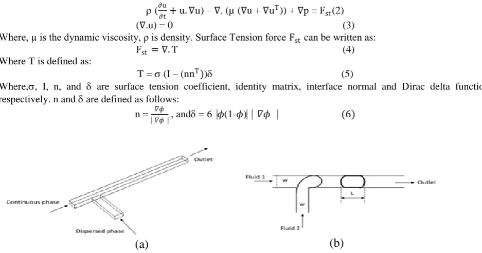
II. THEORY
junction is a one of the most effective geometry for the production of microdropletsin two phase systems [4]. This T-junction consists of two channels; one is the horizontal channel where the continuous fluid flows and another one is the vertical channel to flow the dispersed fluid at different flow rates.
Many physical phenomena exist for fluids in microsystem where dimensionless numbers can be used to determine these aspects for both single phase and multiphase flow microfluidics. These dimensionless numbers are Reynolds number(Re), Weber number (We), and capillary number (Ca) [5].
1. Governing equations
The governing equations for incompressible, immiscible fluids in microfluidics T-junction is given by Navier-stokes as follows [6]:
(∂u
∂t + u. ∇u) – ∇. (µ (∇u + ∇u
T)) + ∇p = F st(2)
(∇.u) = 0 (3)
Where, µ is the dynamic viscosity, ρ is density. Surface Tension force Fst can be written as:
Fst = ∇. T (4)
Where T is defined as:
T = (I – (nnT)) (5)
Where,, I, n, and are surface tension coefficient, identity matrix, interface normal and Dirac delta function, respectively. n and are defined as follows:
n = 𝛻𝜙
⎸𝛻𝜙⎹ , and = 6⎹𝜙(1-𝜙)⎸⎸𝛻𝜙 ⎹ (6)
2. Kinetics of microdroplets
Microdroplets have the small amount of store energy, so the microdroplets do not have the tendency to splash. The total stored energy of droplet is divided into two components.
E = Es+ Ek (7)
Where Es is the surface energy, and Ek is the kinetic energy is expressed as:
E = πd2σ and E =1mu2 = 1πd3u2 (8)
(a)
(b)
Es d02 and Ekd03 (9)
Es
Ek=
1
d0 and Ek
Es = 1
12
u2Lch
σ =
1
12we (10)
Where d0 is the droplet diameter, Lch is the characteristics length, and weis Weber number, which states that miniaturization of the droplet is possible at high surface energy and low kinetic energy. At the micro scale, the Weber number is small which is directly proportional to the droplet size.
III. SIMULATIONANDRESULTS
1. Boundary conditions
To build a two-phase flow inside a microchannel, we used the laminar and incompressible two-phase flow; level set physics in COMSOL Multiphysics tool. As shown in the geometry of T-junction, the two inlet channels for fluid 1 (continuous) and fluid 2 (dispersed) were used. They have different volume flow rates V1 (.22µL/sec) and V2 (.02µL/sec) respectively. At the outlet, default pressure with viscous stress boundary conditions is set accordingly. The geometry used predefined wetted walls boundary condition at the solid wall with a contact angle of 135°. The „physics controlled‟ meshing scheme was chosen with “finer” element size The viscosities of the fluid 1 and fluid 2 were kept at 1.95e-3 Pa.s and 6.71e-3 Pa.s respectively. The densities of fluid 1 and fluid 2 were maintained at 1000 kg/m3. The interfacial tension γ between two flow phases were kept .005 N/m.
The droplet formation inside T-junction at various times period is shownin figure 2 with images (a) – (f). The darker blue shade is the dispersed fluid that forms the droplet while the lighter red shade is a continuous fluid. This formation and the size of droplets can be controlled by using the some physical parameters as a viscosity of the continuous fluid, flow rate of the continuous fluid and dispersed fluid, interfacial tension and geometry dimension of the structure [8].
Fig.2. The images (a) – (f) shows the full cycle of the formation of microdroplets (darker blue shade) in continuous fluid phase (red shade) at different time (t) interval in second (s).
(f) t= 0.05s (e) t= 0.04s
(d) t= 0.03s (c) t= 0.02s
2. Effect of physical parameters
There were four distinct parameters, which incorporate the investigation of this paper. These parameters give the data about the proficient,droplets generation in microfluidics lab on a chip device.
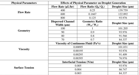
TABLE 1:Exploratory consequences of theimpact of particular parameters for droplet generation in microfluidics T-junction.
Physical Parameters Effects of Physical Parameter on Droplet Generation
Flow Rate
Flow Rate (µL/hr) Flow Ratio (Qd/ Qc) Droplet Size (µm)
400 0.25 139.759
600 0.1667 122.892
800 0.125 93.976
Geometry
Dispersed Channel Width (µm)
Geometry Ratio (Wd / Wc)
Droplet Size (µm)
100 1 101.205
90 0.9 93.976
80 0.8 91.566
70 0.7 84.337
Viscosity
Viscosity of Continuous Fluid (Pa*s) Droplet Size (µm)
0.00095 101.031
0.00195 93.976
0.00295 91.409
0.00395 76.976
Surface Tension
Interfacial Tension (N/m) Droplet Size (µm)
0.005 93.976
0.004 86.747
0.003 84.337
Here we performed each experiment on a single parameter where other was maintained at the boundary condition. These parameters play an effective role in generating droplet and controlling its frequency of generation as shown in Table 1. The effects of these parameters are such as:
Continuous fluid plays a significant role in the formation of droplets. The controlled shape and size droplets can be generated by varying the flow rate of the continuous fluid. The droplet size is reduced and increased by increasing the flow rate of Qfluid 1 and flow ratio of both fluids respectively as shown in fig. 3(d).
The droplet length is also affected by width ratio of the continuous channel to dispersed channel. The contact angle between the channel wall and water droplet is taken as 135°. The wider the width of dispersed channel causes, the length of the droplet is also increased as shown in fig. 3 (c).
Interfacial tension creates an interesting phenomenon during the droplet formation, which is a one of the key factors for the breakup and stability of the droplets in a microchannel. This surface tension is only the conservative force to keep the droplets attached at the junction therefore at low values of interfacial tension, equilibrium of forces reached resulting in faster droplet formation and hence the droplet length gets smaller[8]. The frequency of generation of droplets in a microchannel can be increased or decreased by varying the interfacial tension with precise controlled shape droplet.
It demonstrated that under conditions that are typical for the use of the microfluidics T-junction (width, viscosity, flow rate and interfacial tension), the dominant effect of the break-up of liquid streams in the continuous fluid is the balance of hydrostatic pressures in the two immisciblefluids.
(a)
(b)
(c) (d)
(i) (ii)
(iii) (iv)
(a) SU-8 mold using photolithography
(b) Fabrication of PDMS slab
(c) Detachment of PDMS slab
(d) Holes for inlet and outlet
(e) Bonding to glass slide
Si SU-8 Glass
Fig.4. Fabrication steps of the microfluidics T-junction
IV. PROPOSEDFABRICATIONPROCESS
Micro fabrication of microfluidics T-junction can be achieved with silicon, which includes film deposition, photolithography, isotropic or anisotropic etching steps and anodic bonding of a microchip [9]. Glass can be used because of its great superior optical transparency and excellent high-pressure resistance. However, nowadays most commonly popular microfluidics devices are made of polymers, in particular, poly-dimethylsiloxane (PDMS), owing to its cheaper, robust and allow rapid prototyping. The fabrication procedure of such microdeviceis based on soft lithography for producing a mold, and then casting of PDMS replicas from this mold, followed by bonding the PDMS slab to the glass slide to seal the microchannel [9]. The “negative photoresist” SU-8 is used to make a mold due to its simplicity of production, and it also helps to achieve the broad range of channel thickness from a few microns to several hundred microns.
V. CONCLUSION
ACKNOWLEDGEMENT
The authors are thankful to the Department of Materials Research Centre, Malaviya National Institute of Technology for providing facilities and support to carry out this research work.
REFERENCES
[1] George M. Whitesides, “ The origins and the future of microfluidics”, Nature, |Vol|442:368-373, 2006.
[2] Ashleigh B. Theberge, Fabienne Courtois, Yolanda Schaerli, Martin Fischlechner; Chris Abell, Florian Hollfelder, Wilhelm T. S. Huck, “ Microdroplets in Microfluidics: An Evolving Platform for Discoveries in Chemistry and Biology”, Wiley-VCH Verlag GmbH & Co. KGaA, Weinheim, Angew. Chem. Int., 49:5846-5856, 2010.
[3] Piotr Garstecki, Michael J. Fuerstman, Howard A. Stone, George M. Whitesides, “Formation of droplets and bubbles in a microfluidic T-junction-scaling and mechanism of break-up”, The Royal Society of Chemistry, 6:437-446, 2006.
[4] Shia-Yen The, Robert Lin, Lung-Hsin Hung, Abraham P. Lee, “Droplet microfluidics”, The Royal Society of Chemistry, 8:198-220, 2008. [5] Chun-Xia Zhao, Anton P. J. Middelburg, “Two-phase microfluidic flows”, Chemical Engineering Science, 66:1394-1411, 2011.
[6] A. Salari, C. Dalton, “Flow Focusing Droplet Generation Using Linear Vibration”, COMSOL Conference in Boston, 2014.
[7] Y. Shi, G. H. Tang, H.H. Xia, “Lattice Boltzmann Simulation of Droplet formation in T-junction and flow focusing device”, Computers & Fluids, 90:155-163, 2014.
[8] J. Tan, J.H. Xu, S.W. Li, G.S. Luo, “ Drop dispenser in a cross-junction microfluidic device: Scaling and mechanism of break-up”, Chemical
Engineering Journal, 136:306-311, 2008.