ISSN: 2319-8753
I
nternational
J
ournal of
I
nnovative
R
esearch in
S
cience,
E
ngineering and
T
echnology
(An ISO 3297: 2007 Certified Organization) Vol. 3, Issue 10, October 2014
Study of Chip Reduction Coefficient in Boring
Operation Using Metal Laminates at the
Tool-Holder Interface
Tanmaya Mohanty
School of Mechanical Engineering, KIIT University, Bhubaneshwar, India.
ABSTRACT:Internal machining processes, such as boring operation are challenged by inherent tool vibrations. These
vibrations can be damped to considerable extent employing suitable arrangement to dissipate part of strain energy. The present research has used a set of metal laminates at the tool and tool holder interface. The arrangement which promotes frictional energy dissipation has resulted in improvement of machinability, measured in terms of Chip reduction Coefficient.
KEYWORDS: Boring, tool vibration, chip reduction coefficient (CRC)
I. INTRODUCTION
Internal machining processes need be performed in many parts that arrive at production floors. The parts usually are drilled to a nearer diameter and accurate dimensions are obtained using boring. Though there are dedicated boring machines in heavy industries most of the job shops do rely on lathe machines to carry out the required boring operations. Achievable surface finish of the internal surfaces, though a much desirable property, is usually limited owing to inherent structural characteristic of a boring tool. The cantilevered structure of the boring bar is usually susceptible to vibrations at the free end that is the insert end especially in horizontally operated machine tools. These vibrations unless damped out, can produce detrimental effects including poor surface quality and reduced tool life. The least controlled vibrations come from dynamic instability of the cutting process. These are referred to as self excited vibrations or chatter. These arise out of dynamic interaction between the cutting process and the machine tool structure. Self-excited vibrations known as chatter become increasingly problematic in boring due to the tool overhang. Generally, the rate of material removal is reduced to maintain stability, but this causes a substantial decrease in productivity. Boring bars for single-point turning on a lathe are particularly susceptible to chatter and have been the subject of numerous studies.
ISSN: 2319-8753
I
nternational
J
ournal of
I
nnovative
R
esearch in
S
cience,
E
ngineering and
T
echnology
(An ISO 3297: 2007 Certified Organization) Vol. 3, Issue 10, October 2014
behaviour of the spindle tool system. External magnetic field used changes the stiffness of the MR fluid. Wang and Fei [13-16] used electrorrheological fluid to control the stiffness of the boring bar. Multiple tuned mass dampers have been designed and optimally tuned by Yang et al [17] to increase the chatter resistance. Yong et al [18] proposed an active and adaptive vibration control system to automatically detect sinusoidal vibration parameters in a cantilever beam and generate a control signal to cancel the vibration. L. Andren et.al [19] measured boring bar vibrations in direction of cutting speed and cutting depth with accelerometers. They inferred the vibrations to be influenced by non-stationary parameters not in operator’s control.
Researches carried out by Nanda et al [20,21] display that structural damping is induced when layering is used in beams. The bolt spacing, tightening torque, number of layers affect the damping to significant extent. This motivated the present work to undertake research on laminated tool clamping device and investigate the machining performance in boring. Because of laminated layers, friction will be prevalent. Since friction accounts for a non-recoverable strain energy, the damping of the system is expected to improve. It is expected to give rise to better machining performance. The present work has considered chip reduction coefficient to be the machining performance measure.
Chip reduction coefficient is one of the important machining performance indices. Decreasing chip reduction coefficient indicates improvement in cutting tool life, surface finish and the energy required for machining. The effect of clamping parameters on the chip reduction coefficient has been investigated.
Methodology
II. MATERIALSANDMETHOD
The experiments to determine the chip reduction coefficient under varying cutting conditions were conducted using the High Precision Lathe machine NH 22 in dry condition. The ambience conditions were controlled since the operations were carried out in an air conditioned environment. The experiments were conducted at different cutting speeds using 1-6 layers of packing sheets at the tool-tool holder interface made up of different materials (Fig1). The equipment and instruments used in the investigation included boring tool, tool holder, torque wrench, packing sheets and a digital calliper besides the lathe machine. Chip reduction coefficient was measured for each of the experiment conducted after collecting the chips (Fig 2). The chip thickness has been computed as average of three measurements done to evaluate the chip thickness after each machining operation. The chip reduction coefficient has been obtained by taking the ratio of the chip thickness to uncut chip thickness that is the feed since the process can be considered orthogonal. During all experiments feed, depth of cut, the tightening torque at the tool, work-piece material and tool parameters have been maintained same.
ISSN: 2319-8753
I
nternational
J
ournal of
I
nnovative
R
esearch in
S
cience,
E
ngineering and
T
echnology
(An ISO 3297: 2007 Certified Organization) Vol. 3, Issue 10, October 2014
Fig 2: Types of metal chips obtained after boring
III.RESULTSANDDISCUSSION
Variation of Chip reduction coefficient with respect to number of packing layers:
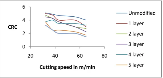
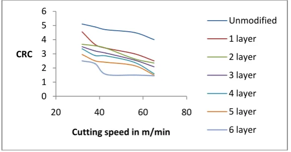
Figure 3 to Figure 7 illustrate the variation of chip reduction coefficient while varying the number of packing layers at the tool support from one to six. The scattered line diagrams have been plotted at different cutting speeds. Figure 3 to 7 depict the variation using GI, Copper, Aluminium, Brass and MS support sheets respectively. The patterns observed in the variation pattern clearly exhibit a reducing trend in the chip reduction coefficient with increase in number of layers of the packing sheets at the tool support. Also using linear trend line fitting a reducing slope in general at increasing cutting speed can be seen. The general pattern in all cases using different packing materials implicates a reduction in chip reduction coefficient while increasing the number of layers of packing sheets.
Well established theories point out that the reduction in chip reduction coefficient indicates less thickening of the chips. Since the shearing stress value of the work piece at normal cutting conditions do not vary much, lower thickening leads to imply a lower cutting force or lower power consumption. The experiments thus yield that; by increasing the number of layers of packing materials one can obtain a lower cutting force. The decreasing rate is obtained from the slopes of the linear trend lines associated with each of the curve. Since the slopes gradually change from -0.478 to -0.271, the effect can be observed to be highly predominant at lower cutting speeds.
Boring bars present cantilevered structure, which on impact with the work piece surface, gets induced with vibrations. Unless damped, the amplitude set at the tool tip is considerable and thus resulting in a contact with non-uniform pressure at the contact surface. Since the pressure is non uniform there always is a probability of periodic impact loads by the tool on the work piece and resulting in higher tool wear thus necessitating higher cutting force. By using the number of layers the attempts to damp the vibrations have been successful in reducing cutting force.
Chip reduction coefficient was measured for each of the experiment conducted. The chip thickness has been computed as average of three measurements done to evaluate the chip thickness after each machining operation. The chip eduction coefficient has been obtained by taking the ratio of the chip thickness to uncut chip thickness that
Figure 3: Chip reduction coefficient vs cutting speed at different number of layers of GI packing sheets
0 2 4 6
20 40 60 80
CRC
Cutting speed in m/min
Unmodified
1 layer
2 layer
3 layer
4 layer
ISSN: 2319-8753
I
nternational
J
ournal of
I
nnovative
R
esearch in
S
cience,
E
ngineering and
T
echnology
(An ISO 3297: 2007 Certified Organization) Vol. 3, Issue 10, October 2014
Figure 4: Chip reduction coefficient vs cutting speed at different number of layers of Copper packing sheets
Figure 5: Chip reduction coefficient vs cutting speed at different number of layers of Aluminium packing sheets
Figure 6: Chip reduction coefficient vs cutting speed at different number of layers of Brass packing sheets
0 1 2 3 4 5 6
20 40 60 80
Surface Roughness in microns
Cutting speed in m/min
Unmodified
1 layer
2 layer
3 layer
4 layer
5 layer
6 layer
0 1 2 3 4 5 6
20 40 60 80
CRC
Cutting speed in m/min
Unmodified
1 layer
2 layer
3 layer
4 layer
5 layer
6 layer
0 1 2 3 4 5 6
20 40 60 80
CRC
Cutting speed in m/min
Unmodified
1 layer
2 layer
3 layer
4 layer
5 layer
ISSN: 2319-8753
I
nternational
J
ournal of
I
nnovative
R
esearch in
S
cience,
E
ngineering and
T
echnology
(An ISO 3297: 2007 Certified Organization) Vol. 3, Issue 10, October 2014
Figure 7: Chip reduction coefficient vs cutting speed at different number of layers of MS packing sheets
Variation of Chip reduction coefficient with respect to cutting speed
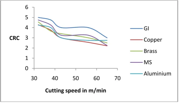
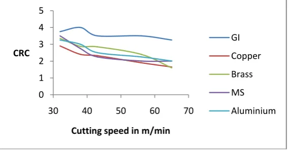
Figure 8 to Figure 12 illustrate the variation of chip reduction coefficient while varying the cutting speed. Chip reduction coefficient is an index to reflect the degree of deformation associated in which the thickness of the chip increases and length shrinks. There have been numerous research articles which have clearly depicted a reduction in chip reduction coefficient with respect to cutting speed and the similar pattern is observed in these experimentations too. Lower chip reduction coefficient is being observed when six numbers of layers of packing material is being used. This is noted for all the range of cutting speeds and materials used as packing sheets.
Since the tool materials, geometrical parameters and the cutting environment are kept same during all the experimentation the effects on chip reduction coefficient are primarily due to cutting tool deflection owing to vibrations induced at cutting tool tip. Since with increase in number of layers of packing material sheet a reduction in chip reduction coefficient is clearly visible, we must accept the significant effect that the number of layers are having.
Figure 8: Chip reduction coefficient vs cutting speed using 1 layer of packing sheet made up of different material
0 1 2 3 4 5 6
20 40 60 80
CRC
Cutting speed in m/min
Unmodified
1 layer
2 layer
3 layer
4 layer
5 layer
6 layer
0 1 2 3 4 5 6
30 40 50 60 70
CRC
Cutting speed in m/min
GI
Copper
Brass
MS
ISSN: 2319-8753
I
nternational
J
ournal of
I
nnovative
R
esearch in
S
cience,
E
ngineering and
T
echnology
(An ISO 3297: 2007 Certified Organization) Vol. 3, Issue 10, October 2014
Figure 9: Chip reduction coefficient vs cutting speed using 2 layers of packing sheet made up of different material
Figure 10: Chip reduction coefficient vs cutting speed using 3 layers of packing sheet made up of different material
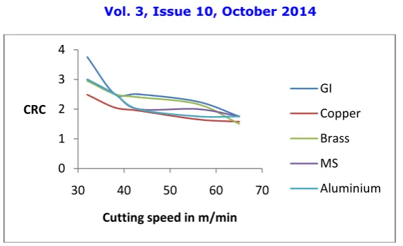
Figure 11: Chip reduction coefficient vs cutting speed using 4 layers of packing sheet made up of different material
0 1 2 3 4 5
30 40 50 60 70
CRC
Cutting speed in m/min
GI
Copper
Brass
MS
Aluminium
0 1 2 3 4 5
30 40 50 60 70
CRC
Cutting speed in m/min
GI
Copper
Brass
MS
Aluminium
0 1 2 3 4 5
30 40 50 60 70
CRC
Cutting speed in m/min
GI
Copper
Brass
MS
ISSN: 2319-8753
I
nternational
J
ournal of
I
nnovative
R
esearch in
S
cience,
E
ngineering and
T
echnology
(An ISO 3297: 2007 Certified Organization) Vol. 3, Issue 10, October 2014
Figure 12: Chip reduction coefficient vs cutting speed using 5 layers of packing sheet made up of different material
Significance Testing
Analysis of variance is a powerful statistical tool to determine the significance level of a variable. In order to predict whether the cutting speed, number of layers and the material of packing sheets have significant effect on chip reduction coefficient or not, a two factor ANOVA without replication has been carried out using Add ins features of MS Excel. The first test has been carried out to check the significance of cutting speed and number of layers. The second ANOVA has been carried out to test significance of material of the packing sheets. As the test results indicate it becomes evident that all three factors including cutting speed, number of layers of packing sheets and the material of the packing sheet have significant effect on the chip reduction coefficient.
IV.CONCLUSION
Chip reduction coefficient decreases with increase in number of layers of packing materials. This indicates presence of favourable conditions, when number of layers of packing sheets is increased in the laminated clamping device. It also indicates low power consumption.
No single material can be sorted out which shall be responsible for reducing the chip reduction coefficient.
Cutting speed, number of layers of the packing sheets in the laminated clamping device and the material of the packing sheet contribute significantly to the chip reduction coefficient. The contribution of the material is found to be least significant.
REFERENCES
[1] Seifring, L., “Apparatus and Method for Tool Vibration Damping”, U.S. Patent, No. 5033340, 1991. [2] Hopkins, D. A., “Vibration Damping Assembly”, U.S. Patent, No. 3938626, 1976.
[3] Sexton, J. S., Milne, R. D., and Stone, B. J., “A Stability Analysis of Single Point Machining with Varying Spindle Speed", Appl. Math. Modelling, Vol. 1, p.310, 1977.
[4] Thompson, R. A., “Method and Apparatus for Optimizing Grinding”, U.S. Patent,No. 4604834, 1986.
[5] Nachtigal, C. L., Klein, R. G., and Maddux, K. C., “Apparatus for Controlling Vibrational Chatter in Machine-tool Utilizing an Updated Synthesis Circuit”, U.S. Patent, No. 3967515, 1976
[6] Den Hartog, J. P., “Mechanical Vibrations”, Dover, New York, 1985
[7] Tewani, S. G., Walcott, B. L., and Rouch, K. E., “Active Optimal Vibration Control using Dynamic Absorber", Proceedings of the 1991 IEEE International Conference on Robotics and Automation, Vol. 2, p. 1182., 1991
[8] Tewani, S. G., Switzer, T. C., Walcolt, B. L., Rouch, K. E., and Massa, T. R., “Active Control of Machine Tool Chatter for a Boring Bar: Experimental Results," in ASME Vibration and Control of Mechanical Systems, DE-Vol. 61, p. 103., 1993
0 1 2 3 4
30 40 50 60 70
CRC
Cutting speed in m/min
GI
Copper
Brass
MS
ISSN: 2319-8753
I
nternational
J
ournal of
I
nnovative
R
esearch in
S
cience,
E
ngineering and
T
echnology
(An ISO 3297: 2007 Certified Organization) Vol. 3, Issue 10, October 2014
[9] Rivin, E. I. and Kang, H., “Improvement of machining conditions for slender parts by tuned dynamic stiffness of tool’, International Journal of Machine Tools Manufacturing 29, 361–376, 1989
[10] Matsubara, T., Yamamoto, H., andMizumoto, H., “Chatter suppression by using piezoelectric active damper”, in ASME Design Engineering Division, DE-Vol. 18-2, ASME, New York, pp. 79–83, 1989
[11] Ema , S., Marui, E., “Suppression of chatter vibration of boring tools using impact Dampers”, International Journal of Machine Tools & Manufacture 40, 1141–1156, 2000
[12] Weck, M., Hennes, N., Krell, M., “Spindle and Toolsystems with High Damping”, Laboratory of Machine Tools, Aachen, Germany Received on January 7,1999
[13] Wang, M. and Fei, R., “Improvement of Machining Stability Using a Tunable-Stiffness Boring Bar Containing an Electrorheological Fluid”, Smart Materials and Structures, 8(4):511–514, 1999
[14] Wang, M. and Fei, R., “Chatter Suppression Based on Nonlinear Vibration Characteristics of Electrorheological Fluid”, International Journal of Machine Tools and Manufacture, 39(12):1925–1934, 1999
[15] Wang, M. and Fei, R., “On-Line Chatter Detection and Control in Boring Based on an Electrorheological Fluid”, Mechatronics, 11(7):779– 792., 2001
[16] Wang, M. and Fei, R., “The Stability Analysis of Machining with Controllable Time Varying Dynamics”, Technical paper – Society of Manufacturing Engineers, n MR02-147, 1–7, 2002
[17] Yang, Y. Munoa, J. and Altintas, Y., “Optimization of multiple tuned mass dampers to suppress machine tool chatter”, International Journal of Machine Tools & Manufacture, doi:10.1016/j.ijmachtools.2010.04.011, 2010
[18] Yong Xia, and Ahmad Ghasempoor, “Active Vibration Suppression Using Neural Networks”, Proceedings of the World Congress on Engineering, Vol II, WCE 2009, July 1 - 3, London, U.K., 2009
[19] Andren, L., Hakansson, L., Brandt, A., Claesson, I., “Identification of dynamic properties of boring bar vibrations in a continuous boring operation”, Mechanical Systems and Signal Processing 18, 869–901, 2004
[20] Nanda, B. K., Behera, A.K., “Study on damping in layered and jointed structures with uniform pressure distribution at the interfaces”, Journal of Sound and Vibration 226, 607–624, 1999

![Methyl 6 oxo 4 phenyl 2 [(Z) 2 (pyridin 2 yl)ethenyl] 1,4,5,6 tetrahydropyridine 3 carboxylate](data:image/gif;base64,R0lGODlhAQABAIAAAP///wAAACH5BAEAAAAALAAAAAABAAEAAAICRAEAOw==)