Division VI, Paper No. 173
SUMMARY OF CHANGES TO THE UPCOMING REVISION OF ASCE 43
AND IMPACTS ON THE DESIGN AND ANALYSIS OF NUCLEAR
STRUCTURES
F.G. Abatt1, Michael W. Salmon2, Andrew S. Whittaker3
1 Senior Engineering Advisor, Becht Engineering; Vice-Chair, ASCE Dynamic Analysis of Nuclear
Structures Committee, USA
2 Lead Engineer, Office of Seismic Hazards and Risk Mitigation, Los Alamos National Laboratory; Chair,
ASCE Dynamic Analysis of Nuclear Structures Committee, USA
3 Professor, Department of Civil, Structural, and Environmental Engineering, University at Buffalo;
Director, MCEER; Chair, ASCE Nuclear Standards Committee, USA
ABSTRACT
ASCE/SEI Standard 43, “Seismic Design Criteria for Structures, Systems, and Components in Nuclear Facilities,” is a consensus US national standard developed by the American Society of Civil Engineers. It provides design criteria for nuclear structures and should be used in conjunction with ASCE/SEI Standard 4. “Seismic Analysis of Safety-Related Nuclear Structures and Commentary”. The two standards are performance based and are written to ensure that structures, systems, and components designed and evaluated in accordance with their provisions meet target performance goals that vary as a function of the seismic design basis.
ASCE/SEI 43 was published in 2005, and is currently being revised with the goal of issuing the updated Standard in 2018. This paper presents a summary of the significant changes in the new revision of ASCE 43 and describes the potential impact these changes may have on the design and analysis of nuclear structures. Significant revisions include the characterization of design response spectra,
procedures for modeling and analysis, the inclusion of new framing systems, and the addition of a chapter on seismic isolation. The paper will also discuss the integration of ASCE/SEI Standards 4 and 43.
OVERVIEW
ASCE/SEI 43 (hereafter referred to as ASCE 43) consists of a Foreword plus ten Chapters arranged as follows:
Foreword
Chapter 1 – Introduction
Chapter 2 – Earthquake Ground Motion Chapter 3 – Evaluation of Seismic Demand Chapter 4 – Structural Capacity
Chapter 5 – Load Combinations and Acceptance Criteria for Structures Chapter 6 – Ductile Detailing Requirements
Chapter 7 – Special Considerations
Chapter 8 – Seismic Qualification of Equipment and Distributions Systems Chapter 9 – Quality Assurance Provisions
All chapters have been updated. The revisions range from significant to more editorial and clarifying. First, the changes to the chapters will be summarized and then potential impacts to the design of nuclear structures will be discussed.
In general, there has been an attempt to more tightly integrate ASCE 43 and ASCE/SEI 4 (ASCE 2017; hereafter referred to as ASCE 4) by more clearly separating seismic design criteria from seismic analysis topics and removing duplication between the two Standards. In some cases, provisions have been removed, simplified, or provided by simply incorporating other Codes and Standards by reference. An example is reference to ACI 349-13 (ACI 2013a) for strength requirements for concrete and reinforcing steel in Chapter 6 in lieu of independently including such details in this Standard.
SUMMARY OF CHAPTER CHANGES
Chapter 1 introduces one of the more significant changes to the Standard with the inclusion of Seismic Design Category 2 (SDC-2), which is in contrast to ASCE 43-05 (ASCE 2005), which only includes SDC-3 through SDC-5. When ASCE 43-05 was written the expectation was that the majority of nuclear facilities would be categorized as SDC-3 and SDC-4, and thus that the provisions of ASCE 43 (and ASCE 4) would apply to such facilities. This expectation was a natural consequence of the fact that ANSI/ANS2.26 did not provide a numerical target performance goal for SDC-2 Structures, Systems, and Components (SSCs) because it was not anticipated that major nuclear facilities would be categorized or designed as SDC-2. It was thought that SDC-2 SSCs would be designed using ASCE 7 and criteria from the International Building Code (IBC), and would not include facilities with significant nuclear inventory. However, the ASCE 43 Working Group recognizes that there are now many facilities with significant nuclear inventory that are categorized and designed as SDC-2 and thus this situation should be addressed by ASCE 43.
The inclusion of SDC-2 was a straightforward decision by the Working Group, but there was considerable discussion and debate as to whether the associated target performance goal should be set at 4
×10-4 Annual Frequency of Exceedance (AFE) or if it should be lowered to 2×10⁻⁴ AFE. The argument for reducing the AFE to 2×10⁻⁴ is based on the recognition that the risk adjusted ground motion in ASCE/SEI 7 (hereafter referred to as ASCE 7) expressed as MCER corresponds to a 1% probability of structural collapse in 50 years (i.e. 2×10⁻⁴ annual probability of collapse). Thus, in nominal terms, it is difficult to accept a model building code with a more stringent target performance goal (2×10⁻⁴ annual probability of collapse) than a nuclear standard (4×10⁻⁴ hazard AFE). That said, such a comparison is anything but direct because the procedures for formulating the performance goals in the two Standards are fundamentally different, namely, performance is judged in ASCE 7 at the system level (building collapse requires the failure of multiple building components) whereas performance is judged in ASCE 43 at the component level. This subject is addressed in Houston et al. (2016) via a case study of a low-rise reinforced concrete shear wall structure.
The argument to lower the target performance goal was ultimately rejected as being based too much on the optics of (tenuous) comparisons between the performance goals of ASCE 43 and ASCE 7. The Working Group also noted that if the target performance goal were set to the lower value of 2×10⁻⁴, it would be so close to the SDC-3 target performance goal of 1×10⁻⁴ that the difference would be nearly indistinguishable in risk space. With this background, the target performance goals for the four SDCs to be included in the next revision of ASCE 43 are shown in Table 1.
Table 1. Target Performance Goals as a Function of Seismic Design Category Seismic Design Category (SDC)
2 3 4 5
Target Performance Goal (PF)
The revision of Chapter 2 on Earthquake Ground Motion introduces a different approach to generating Design Response Spectra (DRS) from Uniform Hazard Response Spectra (UHRS). In both cases, the DRS is determined from two UHRS at different hazard annual exceedance frequencies. ASCE 43-05 defines DRS as the product of a Design Factor (DF) and the UHRS at a specified annual exceedance frequency.
DRS = DF x UHRSHD (1)
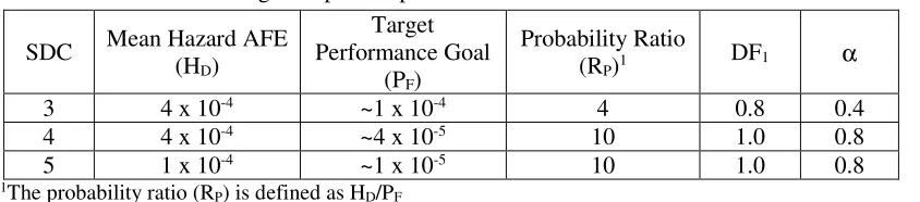
In equation (1), UHRSHD is the Uniform Hazard Response Spectrum at the mean hazard at a specified exceedance frequency. The hazard exceedance frequencies for SDC-3, -4, and -5 designs are given in Table 2. At spectral frequencies for which the UHRS are defined, the DF is determined from the slope factor (AR) and a parameter α as follows:
AR = (SA0.1HD/SAHD) (2)
In equation (2), SAHD is the spectral acceleration at the mean hazard annual exceedance frequency HD and SA0.1HD is the spectral acceleration at 0.1HD. The DF is then defined according to
DF = max(DF1, DF2) (3)
DF2 = 0.6(AR)α (4)
where DF1 and α are defined in Table 2.
Table 2. Design Response Spectrum Parameters from ASCE 43-05
SDC Mean Hazard AFE (HD)
Target Performance Goal
(PF)
Probability Ratio
(RP)1 DF1 α
3 4 x 10⁻⁴ ~1 x 10⁻⁴ 4 0.8 0.4
4 4 x 10⁻⁴ ~4 x 10⁻⁵ 10 1.0 0.8
5 1 x 10⁻⁴ ~1 x 10⁻⁵ 10 1.0 0.8
1The probability ratio (R
P) is defined as HD/PF
The working update to ASCE 43 uses a Scale Factor (SF), less than 1.0, rather than a design factor. The new equation defining the DRS in terms of SF is given by
DRS = SF x UHRSHp (5)
The SF reduces the UHRSHp defined at the target performance goal AFE to get the DRS instead of the previous method of using a DF, which increased the UHRSHD defined at ten times the target performance goal annual frequency of exceedance to obtain the DRS. This change differs from the previous approach using a DF in that inclusion of SDC-2 in the revised Standard led to an inconsistency in the probability ratios (RP) used for SDC-2, -3, -4, and -5. Such an inconsistency existed to a lesser degree in ASCE 43-05 as evidenced in Table 2, but inclusion of SDC-2 exacerbated the situation and made it clear that using the previous method would lead to a different format for the DF for SDC-2 than existed in ASCE 43-05. The new SF method uses an RP of 10 for SDC-2 through SDC-5.
The change in methodology from DF to SF is made for three reasons.
2. The SF is less sensitive to AR than is the DF, particularly over the most likely AR ranges from 2.0 to 4.0.
3. Some hazard curves at low seismic hazard sites have very low ground motions at mean annual hazard AFEs at ten times the target performance goal (HD=10*PF) and at hazard-curve ratios exceeding about 4.5. In such cases the hazard curves cannot be approximated as linear between the HD=10*PF and HPF AFEs when plotted on a log-log plot. Because the ratio is based on a linear approximation, this makes the estimate unreliable. To avoid such problems, a lower bound for the SF is introduced. This constraint is more easily expressed in terms of SF than in terms of DF.
When the slope factor is cast in the form
AR = SAHPF/SAHD (6)
In equation (6), SAHD is the spectral acceleration at the mean AFE HD and SAHPF is the spectral acceleration at the mean AFE HP corresponding to the target performance goal (PF). The SF for this spectral frequency is given by:
SF = max(SF1, SF2, SF3) (7)
SF1 = AR-1.0 (8)
SF2 = 0.6(AR)-0.2 (9)
SF3 = 0.45 (10)
The change in methodology makes essentially no difference in the computed DRS for SDC-4 and SDC-5, and for typical seismic hazard curves makes less than a 5% difference in the DRS for SDC-3. It is easily shown that when RP=10, the scale factor and the design factor are related according to Equation 10.
SF = DF/AR (11)
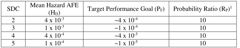
The revised DRS parameters are shown in Table 3.
Table 3. Revised Design Response Spectrum Parameters
SDC Mean Hazard AFE
(HD) Target Performance Goal (PF) Probability Ratio (RP) 1
2 4 x 10⁻³ ~4 x 10⁻⁴ 10
3 1 x 10⁻³ ~1 x 10⁻⁴ 10
4 4 x 10⁻⁴ ~4 x 10⁻⁵ 10
5 1 x 10⁻⁴ ~1 x 10⁻⁵ 10
Varma et al. (2011) and Varma et al. (2013). Requirements for steel-plate composite walls in safety-related nuclear structures are provided in Appendix N9 of ANSI/AISC N690 (AISC 2015).
Chapter 4 now includes steel-plate concrete composite elements as an acceptable structural component for new nuclear facilities. The seismic behavior of this newer framing system for nuclear structures is comparable to reinforced concrete walls provided the reinforcement ratio is similar and the faceplate slenderness ratio (for the SC walls only) comply with limits in Appendix N9 of
ANSI/AISC N690. The chapter provides better integration between ASCE 43 and other national codes and standards by removing detail on structural capacities that had been in ASCE 43-05 and instead referring directly to other codes and standards for such information. The design and detailing of
reinforced concrete is now by reference to ACI 349-13 with a few exceptions, including new provisions for the out-of-plane shear strength of reinforced concrete walls and slabs. These new provisions update the nominal shear stress of unreinforced concrete in ACI 318-14 (ACI 2014), namely, 2 fc′, to account for the effects of section depth, longitudinal reinforcement ratio, and non-exceedance probability on shear strength required of safety-related nuclear structures. Mertz and Whittaker (2018) provide the technical basis for this change, which will affect (and possible increase) the out-of-plane shear reinforcement of reinforced concrete walls and slabs.
The capacity of structural steel components is by reference to ANSI/AISC N690 for carbon steel components, ASCE/SEI 8 for stainless steel components, AISI S100 for cold-formed carbon steel components, and ACI 530/ACI 530.1 (ACI 2013b) for reinforced masonry components. The reference to Section 2108 of the IBC in the context of reinforced masonry has been removed from the Standard.
The design and detailing of carbon steel components is to be performed according to the provisions of ANSI/AISC 341. The revised section on the capacity of structural steel places more emphasis on the LRFD approach and no longer includes individual factors for converting between ASD and LRFD capacities.
The revised Chapter 5 clarifies the delineation between the component level and system level inelastic energy absorption factors (Fµ factors). The provisions give additional guidance on obtaining the
component level Fµ factors and describe the required adjustments to the component level Fµ factors for
weak or soft stories, high frequency response (greater than the amplified portion of the DRS) and the adjustment for ratcheting. The adjustments to the component level Fµ factors result in the system level Fµ
factors.
Table 5-1 of the Standard now includes component level Fµ factors for steel-plate composite
walls and buckling restrained braced frames. Consistent with the emphasis on LRFD, axial load limits in Table 5-1 for special steel moment frames are now expressed in terms of the ultimate axial load rather than the axial yield strength. Table 5-2 on allowable drift ratio limits for structural systems now includes limits for steel-plate composite walls.
The commentary to Chapter 5 includes several new sections. The first is a section on developing project-specific system level Fµ factors for existing structures with non-compliant detailing.
ASCE/SEI 41-13 (ASCE 2014) is introduced in this context, though it is pointed out that the
ASCE/SEI 41 data are developed for different limit states than used in this Standard. The commentary includes a new section that states that the Fµ factors in this Standard are generally conservative even when
used in conjunction with Response Level 3 damping, with or without SSI effects.
Finally, the commentary provides two alternate methods of estimating the system Fµ factor. The
first is based on an estimate of a permissible inelastic distortion. With this established, response analyses are run using inputs scaled to a level at which the elastically computed demand is equal to the yield (or ultimate) capacity. The input is further scaled until the distortion predicted by the nonlinear response history analysis reaches a maximum permissible value. The Fµ factor is equal to this additional scaling
factor. This method may be used to justify an Fµ factor greater than unity for a specific anchorage
configuration although in most cases, anchorage Fµ factors are not significantly greater than unity. In the
weighted elastically computed displacement when the elastic demand is equal to capacity for the critical story. Once the system ductility has been established, there are several approaches for determining the Fµ
factor, which are provided in the commentary to Chapter 5.
To reduce detail and redundancy regarding the requirements for steel and concrete structures, Chapter 6 states simply that steel structures shall meet the minimum requirements of
ANSI/AISC N690-12, and that steel moment frames shall be detailed in accordance with
ANSI/AISC 341. FEMA 350 is no longer included as a reference for detailing of steel moment frames. The commentary on steel structures notes that not only should ANSI/AISC 341 be followed for ductile detailing requirements, but that prequalified special moment frame joints per ANSI/AISC 358
(AISC 2016) should be used.
Similarly, all reinforced concrete structures must meet the minimum requirements of ACI 349-13. In keeping with Chapter 5, Chapter 6 now includes both buckling restrained braced frames and steel-plate concrete composite shear walls, with steel-plate composite shear wall detailing to be in accordance with Supplement 1 of ANSI/AISC N690. The provisions for steel structures now include guidance on the design and analysis of collector items and a new provision that relaxes detailing requirements for Nearly Rigid Platforms and Supports provided that increased loads are considered in the design.
ASCE 43-05 included a provision that weak-axis bending in reinforced concrete walls must be governed by of-plane wall flexure. The new revision includes an alternate approach that allows out-of-plane wall shear to limit the strength with respect to weak-axis bending provided that the out-out-of-plane shear demand is increased by 50% and the Fµ factors for flexure and shear are set to unity. There is also a
new provision governing the detailing of combined shear wall and frame systems in reinforced concrete. The provisions for transverse joint reinforcement in slab-wall moment frame systems have been modified to remove inconsistencies and to reflect the significant difference between beam-column joints (treated in ACI 349-13) and slab-wall joints that are common in some Department of Energy facilities. Strut-and-tie procedures must be used to design slab-wall moment-resisting connections. Three new subsections have been added to the section on reinforced concrete. The first provides requirements for members not proportioned to resist forces induced by earthquake shaking; the second treats collector elements; and the third gives guidance regarding planes of weakness in the seismic load path.
The Chapter 6 provisions take a more liberal stance on use of adhesive anchors in elevated temperature and/or radiation environments. In ASCE 43-05, this practice was prohibited; now the Standard states that adhesive anchors “…shall be qualified in those environments”, with the new commentary on anchorage stating that adhesive anchors that passed tests per ACI 355.4 (ACI 2011) are acceptable for application to nuclear structures.
The procedures for determining sliding and rocking demands for unanchored bodies that were in Chapter 7 of ASCE 43-05 have been moved to ASCE 4-16 because they are analytical procedures that properly belong in ASCE 4. Recognizing that sliding and overturning are not credible failure modes for deeply embedded structures (as defined in the Standard) demonstration of sliding and overturning stability is no longer required for such structures. This change was made to preclude complex checks where no plausible failure mode exists. A related change is that the reduced soil support on the side of a building foundation shall be considered when calculating the side traction for the purposes of sliding checks in embedded structures that are not deeply embedded.
Section 7.5 of the Standard has been condensed to state simply that unreinforced masonry is not an acceptable structural system, but when used as a barrier, shielding, or partition, unreinforced masonry walls shall be designed in accordance with ACI 530.
component is displacement based, then it can be unconservative to set the Fµ factor equal to 1.0 and an
appropriate value of Fµshall be justified.
Section 8.3 on Qualification by Testing and Experience Data and the associated commentary have been revised significantly to emphasize the differences between qualifications by test versus qualification by test experience data and to also update and clarify the factors to be applied to seismic demand for qualification by test, test experience data, and earthquake experience data required to meet the
performance goals of the Standard. The restrictions on the use of factors to be applied to seismic demand are also documented. New sections have been added to the commentary that provide derivations for the factors to be applied to the seismic demand for qualification by testing, test experience data and
earthquake experience data in specific situations.
Section 8.3.2.1 of ASCE 43-05 included the following equation for the demand for qualification by test and test experience data:
D = DNS + 1.4DS (12)
where D is the total demand, DNS is the non-seismic demand, and DS is the elastically computed seismic demand. In ASCE 43-05, the factor of 1.4 is described as the equipment capacity factor for qualification by test or test experience spectra that provides the margin to obtain the required confidence level of performance. Sections 8.3.2.1, 8.3.2.2, 8.3.2.3, and the associated commentary sections of the Standard have been revised to clarify the use and interpretation of the equations governing demand for qualification by test, test experience data, and earthquake experience data, respectively. The revised equation for demand for qualification by test is
D = DNS + γtestDS (13)
The factor γtest is the ratio of the Test Response Spectrum (TRS) to the Required Response Spectrum (RRS) for qualification by testing. If the qualification testing is performed in accordance with IEEE 344, setting the factor γtest to 1.33 will meet the performance goals of this Standard. If testing performed to other procedures and criteria, the value of γtest must be determined by the user so as to meet the performance goals of ASCE 43.
Demand for qualification by test experience data is also given by equation (12), but with γtest replaced by γTES, where γTES is the factor to be applied to the Test Experience Spectrum (TES) required to meet the performance goals of this Standard. For non-relay Generic Equipment Ruggedness Spectra (GERS), setting γTES to 1.33 will meet the performance goals of this Standard. For relay GERS, setting
γTES to 1.75 will meet the performance goals of this Standard. For any component using seismic input other than GERS, γTES must be shown by the user to meet the performance goals of ASCE 43.
The demand for qualification by earthquake experience data is given by the following equation:
D = γEEDDS (14)
The factor γEED is the factor to be applied to earthquake experience data to meet the performance goals of ASCE 43. The seismic demand from earthquake experience data is defined as an Earthquake Experience Spectrum (EES). If the seismic demand Ds is defined by a Seismic Qualification Utility Group (SQUG) reference spectrum (1.5 times the SQUG bounding spectrum), which is an example of an EES, setting γEED to 1.0 will meet the performance goals of ASCE 43. If the earthquake experience data are based on other than a SQUG reference spectrum, the factor γEED must be determined by the user so as to meet the performance goals of ASCE 43. Information on the SQUG reference spectrum is documented in SQUG (2001) and in SSRAP (1991).
approaches and performance goals of the referenced standards can be vetted sufficiently to determine consistency with ASCE 43, it is inappropriate to keep them in the Standard. Also, ASCE 43 addresses only seismic design criteria, where the other codes are more general.
Aside from organizational and editorial revisions, the most significant change to Chapter 9 on quality assurance is the inclusion of detailed provisions on the software quality assurance (SQA).
The Standard specifies requirements for all software used in the analysis and design of SSCs in nuclear facilities, whether acquired or developed. Such software shall be controlled, verified and validated (V&V) prior to the use on a project in accordance with the documented QA program, which shall include a software V&V plan. The plan shall identify significant features of the program that need to be verified, the type of test or benchmark problems, test cases with acceptance criteria and sample problems for installation validation. Acquired computer programs not developed under an approved QA program shall be, as a part of the acquisition process, subject to a dedication activity to provide reasonable assurance that the computer program will perform its intended safety function for SDC-3 to SDC-5. However, such dedication activity (commonly referred to as commercial grade dedication) will not be necessary where the results of such acquired computer programs are verified with the design analysis for each application. All calculations including computer generated ones shall be documented in sufficient detail for a reviewer to determine that the design requirements have been correctly identified and implemented. A graded approach shall be considered for the level of detail and rigor in the documentation.
Chapter 10 is an entirely new chapter on seismically isolated structures, with emphasis on design and on testing of seismic isolation bearings. The text is taken by-and-large from Chapter 12 of
ASCE 4-16, with the intent that the design and testing provisions and commentary that will appear in ASCE 43-xx, will be removed from the next revision of ASCE 4. Kumar et al. (2017) show that the analysis and design provisions of ASCE 4-16 and ASCE 43-xx will achieve the target performance goal for SDC-5.
ACKNOWLEDGMENTS
The authors gratefully acknowledge the members of the ASCE 43 Working Group for their contributions to the Standard and to the material presented in this paper.
NOMENCLATURE
AFE Annual Frequency of Exceedance
AR Slope factor, which is a ratio of spectral accelerations corresponding to a tenfold increase in hazard annual exceedance frequency
D Total demand in the context of equipment qualification DF Design Factor from ASCE 43-05
DF1 Contributing term to the design factor DF2 Contributing term to the design factor
DNS Non-seismic demand in the context of equipment qualification DRS Design Response Spectra
DS Seismic demand in the context of equipment qualification
γtest Factor on the seismic demand for qualification by test that is required to meet the target performance goals of this Standard
γTES Factor on the seismic demand for qualification by test experience spectra that is required to meet the target performance goals of this Standard
γEED Factor on the seismic demand for qualification by earthquake experience data that is required to meet the target performance goals of this Standard
HD Mean hazard AFE at ten times the target performance goal HPF Mean hazard AFE at the target performance goal
PF Target performance goal
RP Probability ratio, which is defined as HD/PF RRS Required Response Spectra
SA Spectral Acceleration
SAHD Spectral acceleration from the mean hazard curve at ten times the performance goal AFE SAHPF Spectral acceleration from the mean hazard curve at the performance goal AFE
SDC Seismic Design Category SF Scale Factor for determining the SF1 Contributing term to the scale factor SF2 Contributing term to the scale factor SF3 Contributing term to the scale factor TRS Test Response Spectra
UHRSHD Uniform Hazard Response Spectra corresponding to an AFE at ten times the target performance goal
REFERENCES
American Concrete Institute (ACI). (2011). “Qualification of post-installed adhesive anchors in concrete and commentary.” ACI 355.4-11, Farmington Hills, Michigan
American Concrete Institute (ACI). (2013a). “Code requirements for nuclear safety-related concrete structures and commentary.” ACI 349-13, Farmington Hills, Michigan.
American Concrete Institute (ACI). (2013b). “Building code requirements and specification for masonry structures and companion commentaries.” ACI 530/530.1-13, Farmington Hills, Michigan.
American Concrete Institute (ACI). (2014). “Building code requirements for structural concrete.” ACI 318-14. Farmington Hills, Michigan.
American Institute of Steel Construction (AISC). (2010). “Seismic provisions for structural steel buildings”. ANSI/AISC 341-10, Chicago, Illinois.
American Institute of Steel Construction (AISC). (2015). “Specification for Safety-Related Steel Structures for Nuclear Facilities, Including Supplement No. 1.” ANSI/AISC N690, Chicago, Illinois.
American Institute of Steel Construction (AISC). (2016). “Prequalified Connections for Special and Intermediate Steel Moment Frames for Seismic Applications.” ANSI/AISC 358-16, Chicago, Illinois. American Iron and Steel Institute (AISI). (2007). “North American specification for the design of
cold-formed steel structural members.” AISI S100-2007, Washington, DC.
American Nuclear Society (ANS). (2004). “Categorization of Nuclear Facility Structures, Systems and Components for Seismic Design.” ANSI/ANS 2.26, La Grange Park, Illinois.
American Society of Civil Engineers (ASCE). (2002). “Specification for the design of cold-formed stainless steel structural members.” ASCE/SEI 8-02, Reston, Virginia.
American Society of Civil Engineers (ASCE). (2005). “Seismic Design Criteria for Structures, Systems, and Components in Nuclear Facilities.” ASCE/SEI-43-05, Reston, Virginia.
American Society of Civil Engineers (ASCE). (2014). “Seismic Evaluation and Retrofit of Existing Buildings.” ASCE/SEI 41-13, Reston, Virginia.
American Society of Civil Engineers. (ASCE). (2016). “Minimum Design Loads for Buildings and Other Structures.” ASCE/SEI 7-16, Reston, Virginia.
American Society of Civil Engineers (ASCE). (2017). “Seismic analysis of safety-related nuclear structures.” ASCE/SEI Standard 4-16, Reston, Virginia.
Epackachi, S., N. H. Nyugen, E. G. Kurt, A. S. Whittaker, and A. H. Varma. (2015a). “In-plane seismic behavior of rectangular steel-plate composite wall piers.” Journal of Structural Engineering, Vol. 141, No. 7, http://dx.doi.org/10.1061/(ASCE)ST.1943-541X.0001148
Epackachi, S., A.S. Whittaker, and Y.-N. Huang. (2015b). “Analytical modeling of rectangular SC wall panels,” Journal of Constructional Steel Research, Vol. 105, pp. 49-59,
Epackachi, S., A. S. Whittaker, A. H. Varma, and E. Kurt. (2015c), “Finite element modeling of steel-plate concrete composite wall piers.” Engineering Structures, Vol. 100, pp. 369-384, http://dx.doi.org/10.1016/j.engstruct.2015.06.023
Houston, T. W, G. E. Mertz, and A. Maham. (2016). “Comparison of seismic design provisions using ASCE 43 with conventional design based on ASCE 7 seismic loads”, Proceedings, ASME 2016
Pressure Vessel and Piping Conference, PVP2016-63681, Vancouver, Canada.
International Code Council. (2015). “International Building Code”, IBC 2015.
Institute for Electrical and Electronics Engineers (IEEE). (2013). “IEEE Standard for Seismic Qualification of Equipment for Nuclear Power Generating Stations.” IEEE 344-2013, Piscataway, New Jersey.
Kumar, M, A. S. Whittaker, R. P. Kennedy, J.J. Johnson, and A. M. Kammerer. (2017). “Seismic probabilistic risk assessment for seismically isolated safety-related nuclear structures”, Nuclear
Engineering and Design, 313 (2017, 386-400.
Mertz, G. E. and A. S. Whittaker. (2018). “Shear strength of plain concrete: addressing depth effects for safety-related nuclear facility applications.” Paper in preparation, Nuclear Engineering and Design. Seismic Qualification Utility Group (SQUG). (2001). “Generic implementation procedure (GIP) for
seismic verification of nuclear plant equipment,” Rev. 3A. Electric Power Research Institute, Palo Alto, California.
Seo, J., A. H.Varma, K. C. Sener, and D. Ayhan. (2016) “Steel-plate composite (SC) walls: In-plane shear behavior, database and design.” Journal of Constructional Steel Research, Vol. 119, pp. 202-215. Senior Seismic Review and Advisory Panel (SSRAP). (1991). “Use of seismic experience and test data to
show ruggedness of equipment in nuclear power plants.” Prepared for the Seismic Qualification Utility Group and in cooperation with the US Nuclear Regulatory Commission, Washington, DC. Varma, A. H., Zhang, K., Chi, H., Booth, P., Baker, T. (2011). “In-plane shear behavior of SC composite
walls: Theory vs. experiment.” Transactions, Structural Mechanics in Reactor Technology, (IASMiRT), North Carolina State University, Raleigh, North Carolina, Paper ID #764.
Varma, A. H., S. Malushte, K. Sener, and Z. Lai. (2013). “Steel-plate composite (SC) walls for safety related nuclear facilities: design for in-plane force and out-of-plane moments.” Nuclear Engineering