Volume 4, No. 5, May 2013 (Special Issue)
International Journal of Advanced Research in Computer Science
RESEARCH PAPER
Available Online at www.ijarcs.info
An Efficient Sic Detection Algorithm for 64-Qam Mimo Systems
Panchumarthi V Bhargavi
P.G Student, Department of ECE SRKR Engineering College
Bhimavaram, AP, India [email protected]
Prof.K.V.S.N.Raju
Head of ECE Department SRKR Engineering College
Bhimavaram, AP, India [email protected]
Buddaraju Revathi
Asst. Professor, Department of ECE, SRKR Engineering College
Bhimavaram, AP, India [email protected]
Abstract: In real propagation environment, channel reuse causes co-channel interference which will degrade MIMO channel performance. A Successive Interference Cancellation (SIC) detection algorithm with 64-QAM technique is used to improve the quality of received signal in a high interference environment. Using Concatenating MMSE with SIC equalization, better cancellation gain can be achieved. In this paper, MMSE-SIC-SORTING has been presented, whose performance is better in high interference environment when compared to the earlier detection schemes like ZF,ZF-SIC,ZF-SIC-SORTING,MMSE,MMSE-SIC etc,.
Keywords: Multiple-Input Multiple-Output (MIMO), Quadrature Amplitude Modulation (QAM), Successive Interference Cancellation (SIC), Bit Error Rate (BER), Signal to Noise Ratio (SNR), Inter Symbol Interference (ISI), Zero Forcing (ZF), Minimum Mean Square Error (MMSE), Trellis Coded Modulation (TCM).
I. INTRODUCTION
Wireless communication is highly challenging due to complex time varying propagation medium. If we consider a wireless link with one transmitter and one receiver the transmitted signal that is launched into wireless environment arrives at the receiver along a number of diverse paths referred to as multipath. These paths occur from scattering and rejection of radiated energy from objects (buildings, hills, trees etc.) and each path a different time-varying delay, angle of arrival and signal amplitude. As a consequence the received signal can vary as a function of frequency, time and space. These variations are referred as fading and cause detoriation of the system quality. Furthermore wireless channel suffer from Co-Channel Interference (CCI) from other cells that share the same frequency channel, leading to distortion of the desired signal and also low system performance. Therefore, wireless system must be designed to mitigate fading and interference to guarantee a reliable communication. A successful method to improve reliable communication over a wireless link is to use multiple antennas.
In wireless communications, it is well known that the channel capacity can linearly increase with the number of antennas (provided that the numbers of transmit and receive antennas are the same) [1], [2]. Thus, to increase the channel capacity, the transmitter and receiver can be equipped with multiple antennas, and the resulting channel becomes a Multiple-Input–Multiple-Output (MIMO) channel.
The growing demand for multimedia services in wireless communications has developed methods to increase system capacity and reliability. In Multiple-Input–Multiple-Output (MIMO) systems, capacity increase is brought about by using the spatial multiplexing mode, which offers capacity proportional to the number of parallel transmit streams that can be created (i.e., the minimum number of transmit and
receive antennas) [3]–[6]. There are MIMO receivers for spatial multiplexing schemes, such as the Maximum-Likelihood (ML) receiver, the linear receiver, the Successive Interference Cancellation (SIC) receiver, etc. [3]. The Maximum Likelihood (ML) receiver is an optimal receiver, but it is difficult to implement due to high complexity arising from exhaustive searches over all candidate vector symbols. On the other hand, linear receivers, such as Zero-Forcing (ZF) or Minimum Mean Square Error (MMSE) receivers, have low decoding complexity, but detection performance decreases in proportion to the number of transmit antennas. Therefore, there has been a study on a practical nonlinear receiver, namely, the Ordered SIC (OSIC) receiver, which successively decodes data streams through nulling and canceling [6].
Although the OSIC receiver requires higher complexity than the linear receiver, it outperforms linear receivers, and its performance is closer to the performance of the ML receiver due to the selection diversity arising from canceling the detected signal out of the received signal [3]. Recently, many studies on multiuser diversity algorithms have been applied to a MIMO system in an attempt to improve the efficiency of system performance. Previous algorithms using multiuser diversity are based on ZF or MMSE receivers and mainly use the theoretical criterion, i.e., capacity maximization, as a performance measure [7].
In the design of wireless communication networks, the limitation on spectrum resources is an important restriction for achieving high bit rate transmissions. The use of M-ary
Quadrature Amplitude Modulation (M-QAM) is considered
an attractive technique to overcome this restriction due to its high spectral efficiency [8], [9].
II. SYSTEMMODEL
et al
receiver (RX). In this paper, Nt is denoted as the number of antenna elements at the transmitter and Nr is denoted as the number of elements at the receiver. Fig 2.1 depicts the Physical MIMO channel. The channel with Nr outputs and Nt inputs is denoted as Nr * Nt matrix.
Fig.2.1 NR X NT MIMO system
Where each entry hi,j denotes the attenuation and phase shift(transfer function) between the jth transmitter and the ith receiver. The MIMO signal model is described as
r = Hs + n
where’ r’ is the received vector of size Nr*1, H is the channel matrix of size Nr*Nt,’s’ is the transmitted vector of size Nt*1, and ‘n’ is the noise vector of size Nr*1.Each noise element is typically modeled as independent identically distributed white Gaussian noise [5], [6] with variance Nt/(2.SNR) [3]. To prevent correlation due to spacing they are typically spaced at least _c/2 where _c is the wavelength of the carrier frequency [5]. The second reason correlation can occur is due to lack of multipath components. It is for this reason that rich multipath is desirable in MIMO system. The multipath effect can be interpreted by each receive antenna being in a different channel. For this reason the rank of MIMO channel is defined as the number of independent equations offered. It is important to note that
Rank (H) ≤ min (Nr, Nt)
And therefore the maximum number of streams that a MIMO system can support is upper bounded by min (Nr, Nt).
Current MIMO system includes MISO and SIMO system that uses MIMO technique to improve the performance of wireless system can be divided into two kinds. One is spatial multiplexing which provides a linear capacity gain in relation to the number of transmitting antenna and the other is spatial diversity schemes which can reduce the BER and improve the reliability of the wireless link.
A. Spatial Multiplexing
The transmission of multiple data stream over more than one antenna is called spatial multiplexing. In this technology multiple antennas are used at both the ends to increase the bit rate in wireless radio link without additional
power or bandwidth consumption. It offers a linear increase in spectral efficiency with the number of antennas. There are two types which have to be taken into account. The first is the V- BLAST (Vertical Bell Laboratories Layered Space-Time) which transmit spatial un-coded data streams without any consideration in equalizing the signal at the receiver. In V-BLAST algorithm, instead of decoding all transmitted signal at the same time, we first decode the ‘strongest’ signal, then subtract this strongest signal from the received signal and proceed to decode the strongest signal of the remaining transmit signal and so on. Other algorithms include
1. Zero Forcing (ZF) algorithm.
2. Minimum Mean square error (MMSE) algorithm. 3. Maximum Likelihood (ML) receiver algorithm.
The ML receiver algorithm can yield the best performance. The second one is realized by space time codes. In contrast to V-BLAST space time codes deliver orthogonal & thereby independent data streams.
B. Diversity Schemes
To improve the link reliability we are using diversity schemes. Spatial diversity improves the signal quality and achieves higher signal to noise ratio at the receiver side. Two kinds of spatial diversities are considered, Transmitter diversity and Receiver diversity. There are two famous space time coding schemes. Space time block code (STBC) and Space time trellis code (STTC).
III. PROPOSEDDETECTIONALGORITHMFOR MIMOSYSTEMS
The co-channel interference is one of the major limitations in cellular telephone network. In the case of cellular network such as 3G or beyond 3G (4G), the co-channel interference is caused by the frequency reuse. Our main idea is to reject the co- channel interference in MIMO cellular systems. To eliminate the inter symbol interference (ISI) occurs in highly interference channel ZF and MMSE equalization techniques are used.
2×2 MIMO channel
In a 2×2 MIMO channel, probable usage of the available 2 transmit antennas can be as follows:
1. Consider that we have a transmission sequence, for example {x 1, x2, x3…. x n}
2. In normal transmission, we will be sending x 1 in the first time slot, x2 in the second time slot, x3 and so on.
3. However, as we now have 2 transmit antennas, we may group the symbols into groups of two. In the first time slot, we send x1 and x2 from the first and second antenna. In second time slot, we send x3 and x4 from the first and second antenna; send x5 and x6 in the third time slot and so on.
4. Notice that as we are grouping two symbols and sending them in one time slot, we need only n/2 time slots to complete the transmission – data rate is doubled.
5. This forms the simple explanation of a probable MIMO
transmission scheme with 2 transmit antennas and 2 receive antennas.
et al
1. The channel is flat fading – In simple terms, it means that the multipath channel has only one tap. So, the convolution operation reduces to a simple multiplication.
2. The channel experience by each transmit antenna is independent from the channel experienced by other transmit antennas.
3. For the ith transmit antenna to jth receive antenna, each transmitted symbol gets multiplied by a randomly varying complex number hj, i. As the channel under consideration is a Rayleigh channel, the real & imaginary parts of hj,i are Gaussian distributed having mean μ hj,i =0 variance σ2hj,i = 1/2.
4. The channel experienced between each transmit to the receive antenna is independent and randomly varying in time.
5. On the receive antenna, the noise n has the Gaussian probability density function with
2 2/2
) ( 2
)
2
/
1
(
)
(
x u ne
n
y
μ=0 and σ2 = N0/2.
6. The channel (hj, i) is known at the receiver.
A. Suboptimal Matched Filtering: 1. Zero forcing (ZF) equalizer:
Let us now try to understand the math for extracting the two symbols which interfered with each other. In the first time slot, the received signal on the first receive antenna is,
12 1 2 , 1 1 , 1 1 2 2 , 1 1 1 , 1 1
n
x
x
h
h
n
x
h
x
h
y
The received signal on the second antenna is,
22 1 2 , 2 1 , 2 2 2 2 , 2 1 1 , 2 2
n
x
x
h
h
n
x
h
x
h
y
y1, y2 are the received symbol on the 1st and 2nd antenna respectively,
h1,1 is the channel from 1st transmit antenna to 1st receive antenna,
h1,2 is the channel from 2nd transmit antenna to 1st receive antenna,
h2,1 is the channel from 1st transmit antenna to 2nd receive antenna,
h2,2 is the channel from 2nd transmit antenna to 2nd receive antenna,
x1, x2 are the transmitted symbols and
n1, n2 is the noise on 1st, 2nd receiver antennas.
We assume that the receiver knows h1,1, h1,2, h2,1 and h2,2. The receiver also knows y1 and y2.The unknowns are x1
and x2. We have two equations and two unknowns. For
convenience, the above equation can be represented in matrix notation as follows:
2 1y
y
=
2 , 2 1 , 2 2 , 1 1 , 1h
h
h
h
2 1x
x
+
2 1n
n
Equivalently, y = Hx+n
To solve for x, we know that we need to find a matrix W which satisfies WH = I. The Zero Forcing (ZF) linear detector for meeting this constraint is given by,
W = (HHH)-1 HH
Using the Zero Forcing (ZF) equalization, the receiver can obtain an estimate of the two transmitted symbols, x^
1 and x^ 2
2 1ˆ
ˆ
x
x
= (HHH)-1 HH
2 1y
y
.2. Minimum Mean Square Error (MMSE) Equalizer:
Let us now try to understand the math for extracting the two symbols which interfered with each other. In the first time slot, the received signal on the first receive antenna is,
12 1 2 , 1 1 , 1 1 2 2 , 1 1 1 , 1 1
n
x
x
h
h
n
x
h
x
h
y
The received signal on the second antenna is,
22 1 2 , 2 1 , 2 2 2 2 , 2 1 1 , 2 2
n
x
x
h
h
n
x
h
x
h
y
Wherey1, y2 are the received symbol on the 1st and 2nd antenna respectively,
h1,1 is the channel from 1st transmit antenna to 1st receive antenna,
h1,2 is the channel from 2nd transmit antenna to 1st receive antenna,
h2,1 is the channel from 1st transmit antenna to 2nd receive antenna,
h2,2 is the channel from 2nd transmit antenna to 2nd receive antenna,
x1, x2 are the transmitted symbols and
n1, n2 is the noise on 1st, 2nd receiver antennas.
We assume that the receiver knows h1,1, h1,2, h2,1 and h2,2. The receiver also knows y1 and y2.The unknowns are x1
and x2. We have two equations and two unknowns. For
convenience, the above equation can be represented in matrix notation as follows:
2 1y
y
=
2 , 2 1 , 2 2 , 1 1 , 1h
h
h
h
2 1x
x
+
2 1n
n
Equivalently, y = Hx+n
To solve for x, we know that we need to find a matrix W which satisfies WH = I. The Minimum Mean Square Error (MMSE) linear detector for meeting this constraint is given by,
W=[HHH+N oI]-1HH
Using Minimum Mean Square Error
(MMSE) equalization, the receiver can obtain an estimate of the two transmitted symbols x1, x2, i.e.
2 1ˆ
ˆ
x
x
= (HHH+N
0I)-1HH
2 1y
y
.B. Optimal Matched Filtering combined with Successive Interference Cancellation:
In Successive Interference Cancellation (SIC), the receiver arbitrarily takes one of the estimated symbols for example the symbol transmitted in the second spatial
dimension x^
2, and subtract its effect from the received
et al
channel becomes a one transmit antenna, 2 receive antenna case and can be optimally equalized by Maximal Ratio Combining (MRC).
Using the Zero Forcing (ZF) equalization approach described above, the receiver can obtain an estimate of the two transmitted symbols x1, x2, i.e..
2 1
ˆ
ˆ
x
x
= (HHH)-1HH
2 1
y
y
Take one of the estimated symbols (for example x^ 2 ) and subtract its effect from the received vector y1 and y2, i.e.
2 1
r
r
=
2 2 , 2 2
2 2 , 1 1
ˆ
ˆ
x
h
y
x
h
y
=
2 1 1 , 2
1 1 1 , 1
n
x
h
n
x
h
Expressing in matrix notation,
2 1
r
r
=
1 , 2
1 , 1
h
h
x1 +
2 1
n
n
r = hx1+n
The above equation is same as equation obtained for receive diversity case.
The equalized symbol is,
W1=hkr/hkh
C. SIC with Optimal detection ordering:
When SIC is used the system performance is affected by the order S in which the layers are detected. That follows
from the previous considerations. If, for example, in a 2×
2-system layer 1 will be detected first, the post-detected SNR will differ from that one, achieved by detecting the layer 2 first. So the layer that leads to the highest post-detection SNR should be detected first for maximizing the systems performance. The proof can be found in [12].
IV. SIMULATIONRESULTS
[image:4.595.336.536.118.293.2]In all simulation results the 2x2 MIMO system in Rayleigh fading channel is taken and the two modulation schemes are applied i.e. BPSK and 64-QAM. Trellis Coded Modulation (TCM) is applied. Channel estimation as well as synchronization is assumed to be ideal.
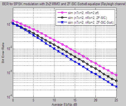
Fig 4.1: 2X2 MIMO System, ZF equalizer, BER vs Eb/No for BPSK modulation with and without SIC
[image:4.595.334.538.343.518.2]Fig 4.1 shows the simulation result for a 2x2 MIMO system with a ZF-equalizer for the case of pure equalization and the combination with Successive Interference Cancellation. SIC is simulated with random and optimal order for BPSK Modulation.
[image:4.595.60.266.567.741.2]Fig 4.2: 2X2 MIMO System, ZF equalizer, BER vs Eb/No for 64-QAM modulation with and without SIC
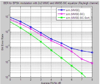
Fig 4.3: 2X2 MIMO System, MMSE equalizer, BER vs Eb/No for BPSK modulation with and without SIC
[image:4.595.333.539.567.739.2]et al
[image:5.595.58.259.119.289.2]Fig 4.2 shows the simulation result for a 2x2 MIMO system with a ZF-equalizer for the case of pure equalization and the combination with Successive Interference Cancellation. SIC is simulated with random and optimal order for 64-QAM Modulation.
[image:5.595.56.262.336.510.2]Fig 4.5: 2X2 MIMO System, Trellis coded MMSE equalizer, BER vs Eb/No for BPSK modulation with and without SIC
Fig 4.6: 2X2 MIMO System,Trellis coded MMSE equalizer, BER vs Eb/No for QAM modulation with and
without SIC
Fig 4.3 shows the simulation result for a 2x2 MIMO system with a MMSE-equalizer for the case of pure equalization and the combination with Successive Interference Cancellation. SIC is simulated with random and optimal order for BPSK Modulation.
Fig 4.4 shows the simulation result for a 2x2 MIMO system with a MMSE-equalizer for the case of pure equalization and the combination with Successive Interference Cancellation. SIC is simulated with random and optimal order for 64-QAM Modulation. For MMSE-equalization the gain through optimal ordering is larger, because the SNR is additionally used for calculating the equalizer.
Fig 4.5 shows the trellis coded MMSE equalization for BPSK modulation which gives performance better than uncoded MMSE equalization. Fig 4.6 shows the Trellis coded MMSE equalization for 64-QAM modulation which gives even better performance than remaining techniques.
V. CONCLUSION
MIMO systems are gaining much more attention and efforts in wireless communication research due to their potential to increase considerable capacity in mobile cellular communication. SIC detection algorithm with 64-QAM technique is used to improve the quality of received signal in a high interference environment.
TCM-MMSE-SIC-SORTING detector for 64-QAM MIMO system performance is better than ZF, SIC, ZF-SIC-SORTING, MMSE and MMSE-SIC.
VI. FUTURESCOPE
Concatenated TCM-MMSE-SIC-SORTING detection performance may be improved by using with the aid of the recent advances in Artificial Intelligence (AI), a range of other problem solving methods have also emerged.
VII. ACKNOWLEDGMENT
Authors like to express their thanks to VIGNAN University and management of SRKR Engineering College for their encouragement and support during this work.
VIII. REFERENCES
[1] I. E. Telatar, “Capacity of multiple-antenna Gaussian
channels,” Eur. Trans. Telecommun., vol. 10, no. 6, pp.
585–595, Nov/Dec. 1999.
[2] G. J. Foschini and M. J. Gans, “On limits of wireless
communications in a fading environment when using multiple antennas,” Wirel. Pers.
[3] A. Paulraj, R. Nabar, and D. Gore, Introduction to
Space–Time Wireless Communications, 1st ed.
Cambridge, U.K.: Cambridge Univ. Press,2003
[4] ] G. J. Focshini and M. J. Gans, “On limits of wireless
communication in a fading environment when using multiple antennas,” Wireless Pers.Commun., vol. 6, no.
3, pp. 311–335, Mar. 1998.
[5] F. R. Farrokhi, G. J. Foschini, A. Lozano, and R. A.
Valenzuela, “Link-optimal space–time processing with
multiple transmit and receive antennas,” IEEE
Commun. Lett., vol. 5, no. 3, pp. 85–87, Mar. 2001.
[6] P. W. Wolniansky, G. J. Foschini, G. D. Golden, and R.
A. Valenzuela, “V-BLAST: An architecture for realizing very high data rates over the rich-scattering wireless channel,” in Proc. ISSSE, Pisa, Italy, Sep. 29,
1998, pp. 295–300. Invited paper.
[7] R. W. Heath, Jr., M. Airy, and A. J. Paulraj, “Multiuser
diversity for MIMO wireless systems with linear receivers,” in Proc. 35th Asilomar Conf. Signals Syst. Comput., Nov. 2001, vol. 2, pp. 1194–1199.
[8] W. T. Webb and L. Hanzo, Modern Quadrature
Amplitude Modulation Principles and Applications for Fixed and Wireless Channels. New York: IEEE Press,
1994. 275
[9] A. Goldsmith and S. G. Chua, “Variable-rate variable
power M-QAM for fading channels,” IEEE Trans.
Commun., vol. 45, no. 10, pp. 1218–1230, Oct. 1997.
J. P. Coon and M. A. Beach, “An investigation of MIMO single-carrier frequency-domain MMSE equalization,” in
Proc London Comm. Symposium, 2002, pp. 237–240.
[10] J. Salz, “Digital transmission over cross-coupled linear
channels,” AT&T Technical Journal, vol. 64, no. 6, pp.
1147–1159, July-August 1985.
[11] P.W.Wolniansky, G. J. Foschini, G. D. Golden, and R.