Graphic User Interface Modelling
and Testing Automation
A thesis submitted in fulfilment of the requirements of the degree of
Doctor of Philosophy
Xuebing Yang
Supervisor: Professor Yuan Miao
School of Engineering and Science
Victoria University
Graphic User Interface Modelling and Testing Automation
DECLARATION
I, Xuebing Yang, declare that the PhD thesis entitled Graphic User Interface Modelling and Testing Automation is no more than 100,000 words in length including
quotes and exclusive of tables, figures, appendices, bibliography, references and footnotes. This thesis contains no material that has been submitted previously, in whole or in part, for the award of any other academic degree or diploma. Except where otherwise indicated, this thesis is my own work.
Graphic User Interface Modelling and Testing Automation
PUBLICATIONS
1. Y. Miao, X. Yang. “An FSM based GUI Test Automation Model”, the 11th
International Conference on Control, Automation, Robotics and Vision, ICARCV 2010. Singapore, December 7-10, 2010
2. X. Yang, Y. Miao and Y. Zhang. Model-driven GUI automation for efficient
information exchange between heterogeneous electronic medical record systems, 19th International Conference on Information Systems Development, ISD 2010. Prague, Czech Republic, August 25 - 27, 2010
3. X. Yang, Y. Miao. Distributed Agent Based Interoperable Virtual EMR
System for Healthcare System Integration. Journal of Medical Systems. August 2009.
4. X. Yang, Y. Miao and Y. Zhang. GP eConnect: Extends e-referrals exchange
Graphic User Interface Modelling and Testing Automation
ACKNOWLEDGMENTS
First and foremost, I would like to express my deep gratitude to my supervisor, Professor Yuan Miao, for his exceptional support, encouragement, and patience during all stages of my research for this dissertation. This dissertation would not have been possible without his invaluable advice and guidance. I feel blessed to have had Professor Miao as my supervisor. I will be forever in his debt.
I also wish to thank my co-supervisor, Professor Yanchun Zhang, for his constant help, discussions, and many constructive suggestions throughout the course of my doctoral study. I have taken the great pleasure in working with my colleagues in the Centre for Applied Informatics Research (CAI) at Victoria University. I would like to thank them for their valuable suggestions and discussions during the process. I thoroughly enjoyed their fruitful collaboration, and I gained invaluable skills by working with them.
I am grateful to the School of Engineering and Science for supplying a very good research environment, and the staff members who frequently offered assistance, particularly the School Postgraduate Coordinator, Dr. Gitesh Raikundalia, A/Prof. Xun Yi, Dr. Fuchun Huang, Professor Pietro Cerone, A/Prof. Hao Shi, and the Scholarship Coordinator for Postgraduate Research, Ms. Lesley Birch.
I am also grateful to our research partner organization Westgate General Practice Network (WGPN) for providing me with a practical working environment, and the staff members who encouraged me through all the stages of my study, particularly the Chief Executive Officer Dr. Corinne Siebel, the Information Management Officer Mr. Manfred Queteschiner, and the Psychologist Ms. Sandra Plant.
Graphic User Interface Modelling and Testing Automation
Graphic User Interface Modelling and Testing Automation
ABSTRACT
A Graphical User Interface (GUI) is the most widely used method whereby information systems interact with users. According to ACM Computing Surveys, on average, more than 45% of software code in a software application is dedicated to the GUI. However, GUI testing is extremely expensive. In unit testing, 10,000 cases can often be automatically tested within a minute whereas, in GUI testing, 10,000 simple GUI test cases need more than 10 hours to complete.
To facilitate GUI testing automation, the knowledge model representing the interaction between a user and a computer system is the core. The most advanced GUI testing model to date is the Event Flow Graph (EFG) model proposed by the team of Professor Atif M. Memon at the University of Maryland. The EFG model successfully enabled GUI testing automation for a range of applications. However, it has a number of flaws which prevent it from providing effective GUI testing. Firstly, the EFG model can only model knowledge for basic GUI test automation. Secondly, EFGs are not able to model events with variable follow-up event sets. Thirdly, test cases generation still involves tremendous manual work.
Graphic User Interface Modelling and Testing Automation
(GUITAM), the development of GUI Defect Classification and the proposal of the Long Use Case Closure Envelope Model.
Graphic User Interface Testing Automation Model. This research proposed a GUI
testing automation model (GUITAM), proved that GUITAM is not only able to automate all testings that EFG can automate, but also able to model a series of important scenarios which EFG cannot. The efficiency of GUITAM, in terms of storage and computational complexity, was also proved to be at least as good as that of the EFG model.
GUI Defect Classification. This research systematically established, for the first time,
a GUI defect classification, which includes criteria of classifying defects, distributions of defects and classification directed test case generation. Defect classification allows test cases to be designed for specific classes of defects, thus effectively avoids large unnecessary permutations in existing models.
Long Use Case Closure Envelope Model. This research proposed a knowledge model
Graphic User Interface Modelling and Testing Automation
TABLE OF CONTENTS
LIST OF FIGURES ... I LIST OF TABLES ... V
Chapter 1 Introduction ... 1
1.1 Conventional software testing. ... 2
1.2 GUI Testing ... 4
1.3 GUI Testing Automation ... 9
1.4 Challenges in GUI Testing Automation ... 15
1.5 Thesis structure ... 17
Chapter 2 Background and Related Work ... 18
2.1 Software Testing Principles ... 18
2.1.1 Terminologies ... 18
2.1.2 Representation of program source code ... 20
2.1.3 Coverage Criteria ... 23
2.1.4 Test Case Generation ... 25
2.1.5 Test Execution ... 26
2.1.6 Regression Testing ... 26
2.2 GUI Testing ... 27
2.2.1 Manual GUI Testing ... 28
2.2.2 Automated GUI Testing ... 28
Graphic User Interface Modelling and Testing Automation
2.3.2 Event Flow Graph (EFG) and Event-Interaction Graph (EIG) ... 39
2.4 Conclusion ... 47
Chapter 3 Graphic User Interface Testing Automation Model ... 49
3.1 What is GUI? ... 49
3.2 GUI states ... 52
3.3 GUI Testing Automation Model ... 56
3.4 Automatic construction of GUITAM. ... 60
3.5 Analysis of GUITAM... 68
3.5.1 Completeness of Algorithm AutoGenerateGUITAM ... 68
3.5.2 Inclusive Mapping between EFG and GUITAM. ... 69
3.5.3 Storage Analysis ... 73
3.5.4 Computational Complexity Analysis ... 74
3.5.5 Dynamic GUI Interactions Modelling ... 76
3.6 Representing Test Case... 81
3.7 GUI Test Coverage Criteria ... 82
3.8 Test Case Generation ... 85
3.8 Test Oracles ... 88
3.8.1 Expected states generation from AUT’s specifications ... 89
3.8.2 Expected states generation from base version of AUT ... 91
3.9 Implementation and Experiment ... 92
3.9.1 Subject Applications ... 95
3.9.2 Automatic GUITAM generation ... 100
3.9.3 Test case generation ... 100
3.9.4 Oracle information ... 101
3.9.5 Test Executor ... 102
3.10 Conclusion ... 108
Graphic User Interface Modelling and Testing Automation
4.1 Introduction to Defect Classification ... 110
4.2 Types of Objects ... 115
4.3 GUI object based Defect Classification ... 122
4.4 Classification directed test case generation ... 126
4.3.1 Functional defects directed test cases generation ... 127
4.3.2 Interactive defects directed test case generation ... 129
4.3.3 GUI adjustment defect directed test case generation ... 132
4.3.4 Functional-interactive defects directed test case generation ... 134
4.4 Experiment ... 138
4.5 Conclusion ... 144
Chapter 5 Long Use Case Closure Envelope Model ... 146
5.1 Use cases representation ... 147
5.2 Backbone of a use case ... 157
5.3 Encapsulating the UCBB with an envelope ... 163
5.4 Use case envelope based test case generation ... 172
5.5 Experiment ... 175
5.6 Conclusion ... 181
Chapter 6 Conclusions and Future Work ... 184
6.1 Major contributions ... 185
6.2 Future work ... 187
Graphic User Interface Modelling and Testing Automation
LIST OF FIGURES
Figure 1.1 Process of conventional software test case execution ……….4
Figure 1.2 GUI and its underlying codes……….……….7
Figure 1.3 Process of GUI test case executions………..……..……….8
Figure 2.1 Types of software testing….……….…………..………21
Figure 2.2 A sample program ………..….…..………22
Figure 2.3 ICFG of the sample program in Figure 2.2………..…………23
Figure 2.4 GUI of Real Juke Box……….….…….33
Figure 2.5 ESG representation of Play and Record a CD system function….…34 Figure 2.6 ESG with FP……….……….35
Figure 2.7 Refinement of the vertices S, P, and M of the ESG in Figure 2.4.…37 Figure 2.8 An example of EFG………..………41
Figure 2.9 Algorithm GetFollows……….………..42
Figure 2.10 Algorithm GenerateEIG……….……...………45
Figure 2.11 The EIG for the EFG of Figure 2.7………..………..46
Figure 3.1 GUIs of Simple Clinic Software………….……..…………..………50
Figure 3.2 Hierarchical objects of W1 in Figure 3.1………51
Figure 3.3 Patient details editing GUI in Medical Director 3………..…………55
Graphic User Interface Modelling and Testing Automation
Figure 3.5 Algorithm AutoGenerateGUITAM………….………61
Figure 3.6 Algorithm NavigateTo………....……….63
Figure 3.7 Illustration of AutoGenerateGUITAM algorithm for Simple Clinic Software………68
Figure 3.8 Algorithm TransformEFGtoGUITAM……….……….71
Figure 3.9 A GUITAM model converted from EFG in Figure 2.7….…....…….72
Figure 3.10 Non-fixed follow-up event set of event ‘B1Click’………..………77
Figure 3.11 Non-fixed events set in GUITAM………..………..…………78
Figure 3.12 Expandable panel………79
Figure 3.13 Panel visible changes state in GUITAM………..80
Figure 3.14 General algorithm for criteria-based test cases generating…...…..86
Figure 3.15 Mechanism of generating expected states from specifications.…...89
Figure 3.16 Mechanism of generating expected states from base version of AU...89
Figure 3.17 Algorithm for generating expected states from specification…….….91
Figure 3.18 Algorithm for generating expected states from base version of AUT...92
Figure 3.19 Main interface of Calculator……….96
Figure 3.20 Main interface of EasyWriter………...……….97
Figure 3.21 Main interface of EnglishStudy………..………98
Figure 3.22 the Icon of ScreenDrawer………..99
Graphic User Interface Modelling and Testing Automation
Graphic User Interface Modelling and Testing Automation
Graphic User Interface Modelling and Testing Automation
LIST OF TABLES
Table 1.1 Relative cost of repairing software faults………..………2
Table 2.1 Real Juke Box System functions ……….34
Table 3.1 GUITAM states and their corresponding windows of simple clinic software ……….…………..… 58
Table 3.2 Transitions (events) description for figure 3.4……….………….58
Table 3.3 Comparison between GUITAM Runner and Automation Anywhere ..95
Table 3.4 Subject applications...….………95
Table 3.5 GUITAM information of subject applications………100
Table 3.6 Test cases generated for each subject application………..………100
Table 3.7 Oracle information for each subject application………..…………101
Table 3.8 Types of seeded faults……….……….103
Table 4.1 Distribution of defect types………..……..114
Table 4.2 Object types and their related events………...………115
Table 4.3 Classification of objects………..………119
Table 4.4 Object statistics for Microsoft Offices software………..120
Table 4.5 Object statistics for MD2 and MD3……….………121
Table 4.6 Defect Classes and their related object types……….125
Table 4.7 Distribution of different kinds of objects in subject applications…..…138
Graphic User Interface Modelling and Testing Automation
Graphic User Interface Modelling and Testing Automation
Chapter 1
Introduction
Graphic User Interface Modelling and Testing Automation
interact with software systems. More than 45% of the total source code is used for implementing a GUI which makes GUI testing inevitable. Due to the characteristics of the GUI, GUI testing is much more difficult than conventional software testing. This thesis focuses principally on providing solutions to tackle the difficulties in GUI testing. Before presenting our work, this chapter will introduce conventional software testing and the state-of-art of GUI testing researches.
This chapter is organized as follows. First, the background of conventional software testing is reviewed in Section 1.1. In Sections 1.2 and 1.3, outlines of research on GUI testing and automation are given. Section 1.4 lists the issues in GUI testing automation and summarises our solution. The structure of this thesis will be presented in Section 1.5.
1.1Conventional software testing.
Software testing is one of the most important parts of the life cycle of software system development and costs more than any other part. Software testing is labour and resource intensive. Usually software testing accounts for 50-60% of the total cost of software development [1]. As shown in table 1.1[2], the earlier the faults are found, the less the repair will cost.
Table 1.1 Relative cost of repairing software faults.
Stage Relative cost of repair
Graphic User Interface Modelling and Testing Automation
Coding 1
Unit testing 2
Acceptance testing 5
Maintenance 20
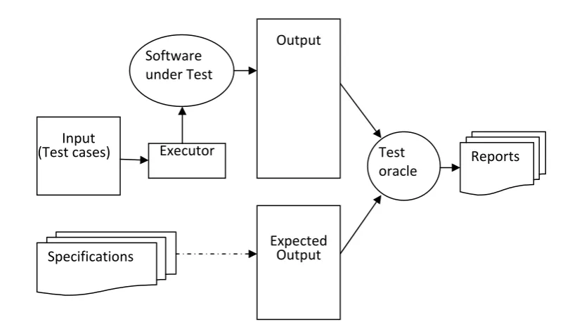
It is impossible to exhaustively test an application. The reasons for this noted by Kaner, Falk, and Hguyen [3] are as follows: (1) the domain of program inputs is too large; (2) there are too many possible input paths, and (3) design and specification issues are difficult to test. In software testing, only a small percentage of possible input combinations can be selected to generate test cases, and these are selected based on certain coverage criteria. Test cases are executed either manually or automatically and check whether the outputs conform to the software specifications.
A conventional software testing procedure encapsulates a number of steps. These steps include test planning, test case generation, test check with oracles, and analysis of the results. Figure 1.1 shows the typical process of conventional software test case execution.
Graphic User Interface Modelling and Testing Automation
Figure 1.1 Process of conventional software test case execution
1.2 GUI Testing
Today, most software products provide GUIs as the main interface for users to access their functions. GUIs have become dominant in comparison with other kinds of interfaces such as command line based consoles. A GUI is a type of user interface that allows users to interact with programs in more ways. A GUI offers graphical icons, and visual indicators to fully represent the information and actions available to a user. The actions are usually performed through direct manipulation of graphical elements. In a typical GUI, instead of laboriously typing commands to tell a computer what to do, a user can simply choose commands by activating or manipulating the pictures. For example, a user may click on a button or drag an icon with an input device such as a mouse. GUIs are intended to make computers "user friendly" by simplifying tasks and
Input
(Test cases) Executor Software
under Test
Output
Expected
Output
Specifications
Test
Graphic User Interface Modelling and Testing Automation
decisions, and by creating a visual representation of a computer system to which people can more easily relate. A significant aspect of GUIs is that they are not merely different to look at, but can increase the efficiency of learning and usage over text-based interfaces. GUIs can also lead to higher productivity because they lend themselves better to performing multiple tasks simultaneously. Well-designed GUIs not only represent files, programs, and procedures visually, but also provide streamlined methods for completing tasks and take into account users' needs and expectations.
Graphic User Interface Modelling and Testing Automation
comprehensive testing of GUIs must be implemented before the software is delivered to the terminal users.
Graphic User Interface Modelling and Testing Automation
with time spans for the GUI to react. Execution of test cases on GUIs is time-consuming. As compared to unit logic, in which 10,000 cases can often be automatically tested within a minute - 10,000 simple GUI test cases need more than 10 hours, which at a cost of 600 times of the former.
Graphic User Interface Modelling and Testing Automation
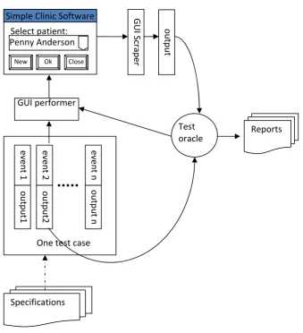
Due to the characteristics of GUIs, which are different from those of traditional software, techniques typically applied to software testing are not adequate for GUI testing. In comparison with conventional software testing, GUI testing involves more effort, such as event simulation. A typical GUI test case execution process is shown in Figure 1.3.
Figure 1.3 Process of GUI test case executions GUI performer
Specifications
Test
oracle Reports
Select patient:
Simple Clinic Software Penny Anderson
New Ok Close
event 1 output1 event 2 output2
One test case
Graphic User Interface Modelling and Testing Automation
In Figure 1.3, in contrast to the conventional test case execution shown in Figure 1.1, each test case includes a series of events. Each event needs to be performed on the given GUI by simulating a user’s operation. Unlike conventional software, GUI based software takes time to react to each event. After the GUI finishes the reaction, a GUI scraper reads the status of all the components and compares them with the pre-stored expected information linked to the event by using a test oracle. Any mismatches in the results may be fed-back to the GUI performer so that it can decide whether the other events of this test case need to be performed or not. All mismatches will be put into a defects report for later analysis. If the GUI performer works manually, each test case needs a long time to execute, normally more than 15 seconds. If the result checking is also done manually, about another 20 seconds are requied. Supposing there are 10,000 cases, the total testing time is about 100 hours. If the test cases are executed automatically by mimicking user operations, it takes about 3 seconds for each test case to be performed and about another 1 second for the oracle check. 10,000 cases need about 10 hours to be executed. Apparently, automatic GUI testing is about 10 times more efficient than manual GUI testing and saves human resources. GUI testing automation has therefore been attracting more and more researchers in recent years.
1.3GUI Testing Automation
Graphic User Interface Modelling and Testing Automation
perform exhaustive testing. Many GUI objects, properties and events are related to each other. Without the knowledge of how these parts are connected and how they work, test cases can only be generated manually. In other words, to automatically generate test cases, comprehensive models are needed to model the whole GUI system of an application. Secondly, after the test cases are generated, they need to be executed automatically. Each test case comprises an event sequence with GUI state and object information linked to them. An executor is used to mimic a user to perform all the events automatically in sequence. Thirdly, the aim of executing the test cases is to check whether the GUI performs as intended. This needs proper mechanisms called ‘test oracles’ to check and report the incongruences. Automatically generating test oracle information for the checking is very difficult for GUI applications. The oracle information can either come from application specifications or from a base version of the application under test. Regressive GUI testing may automatically generate oracle information by executing the same test cases on the base version and recording the corresponding GUI states for comparisons. Some defects may cause incorrect GUI states which can also lead to unexpected events, which can also make further execution of the test cases useless. Consequently, the execution of the test case must be terminated when an error is detected [6]. Furthermore, the test results need to be analysed and reported. The major steps of GUI testing automation are as follows [13].
Graphic User Interface Modelling and Testing Automation
what extent the test will be done. In GUIs, a user may click on a window randomly and a different order of clicks may lead to different results. Since the number of all permutations is extremely huge, only a small number of the sequences may be selected as test cases.
Step 2: Test cases generation. Test cases in GUIs are actually sequences of user inputs.
Each test case is represented as a series of events, such as clicks, keys, or menu selections. According to the given criteria, test cases are selected to perform actions on the GUIs of an application.
Step 3: Test oracles development. Without a mechanism to predict the right output, one
can never tell whether there are faults after performing a test case. Test oracles are used to check the output after each test case is executed. Developing test oracles is tedious and time consuming.
Step 4: Test case execution and output verification. Executing test cases can be done
automatically with a proper GUI state model by simulating a user’s operations on a given GUI. After each step of a test case is executed, the GUI state is retrieved by a GUI Scraper and compared by the oracles. Any faults will be recorded for later analysis.
Step 5: Test results analysis. Once all the test cases have been executed and the
Graphic User Interface Modelling and Testing Automation
software. Which parts of the software are tested and which are not tested should be reported as well.
Step 6: Regression testing. Regression testing is used to help ensure the correctness of
the modified parts of the software as well as to establish confidence that changes have not adversely affected previously tested parts.
All the six steps mentioned above are indispensible to GUI testing. It is so difficult to fulfil GUI testing automation for all the steps that many researchers have been trying partially GUI testing automation [7-13].
GUI testing automation is traditionally through the Capture and Replay (CR) technique [14-15]. CR tools provide a basic automation solution by recording mouse coordinates and user actions as scripts. A major problem of using mouse coordinates is that the scripts can break with even minor changes to the GUI layout [42].
Graphic User Interface Modelling and Testing Automation
application, the unique name will be used to obtain the reference to the real object in the GUI and recorded events will be performed on the designated object.
CR tools are very useful, but inadequate for performing true automation tasks such as GUI testing. They can only record user actions on the GUIs of the given applications and replay these actions. Test automation requires knowledge of the logic or workflow of the GUIs. Researchers have developed a series of techniques for GUI test automation [23-27]. However, these proposals are based on models manually created from the application’s specifications [10, 28-30] which involve much time and resources. This specifications based GUI automation has been proven to be impractical and not really feasible [31-32].
Graphic User Interface Modelling and Testing Automation
path in EFG is a legal executable sequence which can be used as a test case. EFGs can be generated automatically using a tool called GUI Ripping [44]. Traversing the EFG with certain strategy can generate test cases.
The Event Sequence Graph (ESG) [56] is also an event focused model. ESG represents the system behaviour and the facilities from the user’s point of view while interacting with the system. ESGs are directed graphs; their nodes represent events and edges represent valid, correct sequences of events. Two pseudo vertices, ‘[‘and ‘]’, symbolize entry and exit where any node can be reached by entry, and any node can reach the exit. Any sequence of vertices connected by an edge is called a legal event sequence (ES). Two events connected by an edge are called an event pair (EP). An ES starting at the pseudo vertex ‘[‘and ending with the pseudo vertex ‘]’ is called a complete event sequence (CES). CESs are considered to perform successful runs through the ESG, i.e., they are expected to arrive at the exit of the ESG that models an application. In other words, they deliver desirable events. For (positive) testing, CESs are used as test inputs [6].
Graphic User Interface Modelling and Testing Automation
1.4 Challenges in GUI Testing Automation
The characteristics of GUI make GUI testing very difficult. Firstly, event-driven architecture ensures the uncertainty of user inputs. In conventional command line software, inputs can be simply described as strings. In GUI applications, inputs are much more complex. A user may click on any pixel on the screen in any order. Key presses may happen while the mouse is being clicked or pressed. The input space is huge. Secondly, an automatic test suite has to simulate these events somehow. To automate, an automation tool needs to be able to mimic a user performing events. Thirdly, the state of the GUI is a combination of the states of all its components. Even the simplest components have a large number of attributes and methods. A distinct set of a combination of all the attributes constitutes a GUI state. The number of states increases exponentially as the number of components in a GUI increases.
Due to the difficulties of GUI testing, GUI testing automation therefore faces a number of challenges:
Graphic User Interface Modelling and Testing Automation
2) Test case generation. Given the combinatorial explosion due to arbitrary event interleaving, selecting a feasible number of event sequences is paramount. To reduce the number of test cases, some methods try to limit the length of test cases to a certain number of steps. How to automatically generate efficient test cases is a big challenge for all existing GUI Testing Automation models.
3) Oracles development. In GUI testing, the outputs are manifested by the values of properties of widgets in the GUI. The expected values need to be prepared before testing. One of the difficulties is how to arrive at the expected values. Besides, one test case may contain a number of events. After each event is executed, the GUI state needs to be checked. If all the values of the properties of all the widgets are selected, the storage needed is remarkable. How to select values of properties of the widgets for user collecting and checking is another difficulty in oracle development.
4) Coverage of test case suite: Conventional coverage methods are not suitable for GUI testing. GUI behaviours are represented by components statuses and events. The challenges include how to decide what part of the GUI, what kind of behaviour of the GUI or what group of events to be covered and tested. How to define coverage criteria is also a challenge.
Graphic User Interface Modelling and Testing Automation
generating new test suites and how much the previous versions of applications can be used is very important.
This thesis effectively addresses the challenges of existing GUI testing methods and provides a unified solution to GUI testing automation. The three main contributions of this research are the proposal of the Graphic User Interface Testing Automation Model (GUITAM), the development of the GUI Defect Classification and defect classification directed test case generation, and the proposal of the Long Use Case Closure Envelope Model for task-oriented long test case generation.
1.5 Thesis structure
Graphic User Interface Modelling and Testing Automation
Chapter 2
Background and Related Work
The research presented in this thesis focuses on providing a unified solution to GUI modelling and testing automation, which includes GUI representation, GUI testing automation models, defect classification and a knowledge model for task oriented test case generation. This chapter will introduce the background, relevant terminologies, and related research in the area of software testing and GUI testing automation.
2.1 Software Testing Principles
To better understand the whole process of software testing and avoid ambiguity in presentation, some underlying principles in software testing will be introduced in this section.
2.1.1 Terminologies
The purpose of software testing is to reveal software faults in order to correct errors
made during the implementation of the application under test (AUT) and to ensure the quality of the AUT [58]. We say that a program’s execution is correct when its
behaviour matches the functional and non-functional requirements in the AUT’s specifications [57]. An error is a mistake made by a programmer during the
Graphic User Interface Modelling and Testing Automation
program source code statements that cause a failure. A failure of an application is an
external, incorrect behaviour of a program [58]. A defect generally refers to any of
these concepts, including faults, errors and failures.
According to A.M. Memon, M.E. Pollack, G.M. Kapfhammer and M.L. Soffa [43, 59], test suites are used to assess the quality of an AUT. A test suite includes a series of test cases and states.
Definition 2.1[43,49]: A test suite T is a triple (∆0, <T1,…,Te >, <∆1,…, ∆e >), consisting of an initial external test state, ∆0, a test case sequence <T1,…, Te>for state ∆0, and expected external test states <∆1,…, ∆e>,
where ∆f = Tf(∆f-1) for f = 1,…,e. ∆f = {(var∆, val∆) ϵ U∆ × V∆ | value (var∆, f) =val∆}
∆f denotes the externally visible state of the AUT. ∆f can be viewed as a set of pairs where the first of each pair is a variable name and the second is a value. U∆ and V∆ denote the universe of valid variable names and variable values respectively.
Definition 2.2[43,49]: A test case Tf∈ <T1,…,Te> is a triple<δ0, <o1,…,og>, <δ1,…, δg>> consisting of an initial internal test state, δ0, a test operation sequence <o1,…,og>, for state δ0, and expected internal test <δ1,…, δg> , where δh = oh(δh-1) for h = 1, … , g. δh = {(varδ, valδ) ∈ Uδ× Uδ | value (varδ, h) = valδ }
Tfϵ <T1,…,Te> can be viewed as a sequence of test operations that cause the AUT to
Graphic User Interface Modelling and Testing Automation
Definition 2.3[60]: A test suite T is independent if and only if for all γ∈ {1… e}, ∆ γ
= ∆0. Independent suite is a restricted type of suite, where each test case returns the
AUT back to the initial state, ∆0, before it terminates.
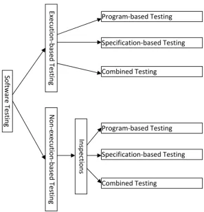
Software testing can be divided into two categories: execution based software testing and non-execution-based testing. Execution-based software testing techniques are either program-based, or specification-based, or combined [61, 62]. Non-execution-based software testing can be performed through software inspections [63]. During a software inspection, software engineers manually examine the source code of a system and any document that accompanies the system. The inspection can be guided by a software inspection checklist [64] or by using scenario-based reading techniques [65, 66]. Figure 2.1 shows the types of software testing.
Non-execution based software testing is usually done manually which is not our focus. The executions in execution-based software testing can be automated to some extent. Many testing automation models are for execution-based testing.
2.1.2 Representation of program source code
Graphic User Interface Modelling and Testing Automation
between the methods within a specific class [67-70]. Inter-procedural Control Flow Graph (ICFG) [71] represents the control flows of each method within an AUT. Different representations for the AUT influence the measurement of the quality of existing test suites and the generation of new tests. These graph-based representations can be generated automatically by scanning the source codes. Here we just introduce the ICFG.
Figure 2.1 Types of software testing
An ICFG is a collection of control flow graphs (CFGs) G1,G2,…, Gu which correspond with the CFGs for the program’s methods m1, m2,…,mu, respectively. We define
Software Tes ting Exe cution ‐ ba sed Testi n g Non ‐ exe cution ‐ based Testi n g
Program‐based Testing
Specification‐based Testing
Combined Testing
Program‐based Testing
Specification‐based Testing
Combined Testing
Graphic User Interface Modelling and Testing Automation
control flow graph Gv so that Gv = (Nv, Ev) and we use Nv to denote a set of CFG nodes and Ev to denote a set of CFG edges. Furthermore, we assume that each n ∈ Nv represents a statement in method mv and each e ∈ Ev represents a transfer of control in method mv. Also, we require each CFG Gv to contain unique nodes entryv and exitv that demarcate the entrance and exit points of method mv, respectively. We use the sets
pred(nτ ) = { nρ | (nρ, nτ ) ϵ Ev} and succ(nρ) = { nτ | (nρ, nτ ) ϵ Ev} to denote the set of
predecessors and successors of node nτ and nρ, respectively. Finally, we require
| 1, and | 1, | to contain all of the nodes and
edges in the inter-procedural control flow graph for a program.
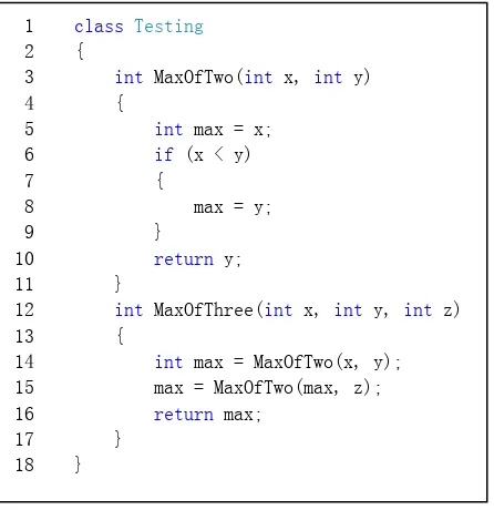
Figure 2.2 A sample program
From the sample program in Figure 2.2, an ICFG can be created for the program which
1 class Testing
2 {
3 int MaxOfTwo(int x, int y) 4 {
5 int max = x; 6 if (x < y) 7 {
8 max = y; 9 }
10 return y; 11 }
12 int MaxOfThree(int x, int y, int z) 13 {
14 int max = MaxOfTwo(x, y); 15 max = MaxOfTwo(max, z); 16 return max;
Graphic User Interface Modelling and Testing Automation
Figure 2.3 ICFG of the sample program in Figure 2.2
2.1.3 Coverage Criteria
Selection of representation of the AUT source code affects the definition of coverage criteria. For reasons of simplicity, in this section ICFG is used as source code representation.
Definition 2.4[74]: A test suite T for control flow graph Gv = (Nv, Ev) satisfies the
all-nodes test coverage criterion if and only if the tests in T create a set of complete paths
ПNv that include all n ∈ Nv at least once.
Definition 2.5[74]: A test suite T for control flow graph Gv = (Nv, Ev) satisfies the
all-edges test coverage criterion if and only if the tests in T create a set of complete paths
ПEv that include all e ∈ Ev at least once.
5
6
8
10
Entry of
MaxOfTwo
Exit of
MaxOfTwo
14
15
16
Entry of
MaxOfThree
Exit of
Graphic User Interface Modelling and Testing Automation
Definition 2.6[74]: A test suite T for control flow graph Gv = (Nv, Ev) satisfies the
all-paths test coverage criterion if and only if the tests in T create a set of complete paths
Пv that include all the execution paths beginning at the unique entry node entryv and ending at the unique exit node exitv.
In a standard program, the occurrence of a variable on the left-hand side of an assignment statement is called a definition of this variable. The occurrence of a
variable on the right hand side of an assignment statement is called a computation-use
(or c-use) of this variable. When a variable appears in the predicate of a conditional
logic statement or an iteration construct, this is called a predicate-use (or p-use) of the
variable. A definition clear path for variable varv is a path <nρ,…,nτ> in Gv, such that none of the nodes nρ,…,nτ contain a definition or undefinition of program variable varv .
Def-c-use association is a triple <nd, nc-use, varv> where a definition of variable varv occurs in node nd and a c-use of varv occurs in node nc-use. Def-p-use association as the two triples <nd, (np-use, t), varv>, and <np-use, f), varv> where a definition of variable
varv occurs in node nd and a p-use of varv occurs during the true and false evaluations
of a predicate at node np-use [72, 73, 75-77].
All-du-paths coverage criterion requires the coverage of all the paths from the
definition to a usage of a program variable [76, 77].
Definition 2.7[76,77]: A test suite T for control flow graph Gv = (Nv, Ev) satisfies the
Graphic User Interface Modelling and Testing Automation
where varv ∈ Uv and nd, nc-use ∈ Nv, there exists a test Tf ∈ <T1,.., Te> to create a complete path in Gv that covers the association.
Definition 2.8[76,77]: A test suite T for control flow graph Gv = (Nv, Ev) satisfies the
all-p-uses test coverage criterion if and only if for each association (nd, (np-use, t), varr) and (nd, (np-use, f),varv),
where varv ∈ Uv and nd, np-use ∈ Nv, there exists a test Tf ∈ <T1,…, Te> to create a complete path in Gv that covers the association.
Definition 2.9[76,77]: A test suite T for control flow graph Gv = (Nv, Ev) satisfies the
all-uses test coverage criterion if and only if for each association <nd, nc-use, varv>, <(nd, (np-use, t), varv> and <nd, (np-use, f), varv>,
where varv ∈ Uv and nd, nc-use, np-use ∈ Nv, there exists a test Tf ∈ <T1,…, Te> to create a complete path in Gv that covers the association.
Definition 2.10[76,77]: A test suite T for control flow graph Gv = (Nv, Ev) satisfies the
all-du-paths test coverage criterion if and only if for each association < nd, nc-use, varv>, <nd, (np-use,t), varv> and <nd, (np-use, f), varv>,
where varv∈ Uv and nd, nc-use, np-use∈ Nv, the tests in T create a set of complete paths
П that include all of the execution paths that cover the associations.
Graphic User Interface Modelling and Testing Automation
The generation of test cases can be performed in a manual or automated fashion. Manual test generation involves the construction of test cases by analysing the source code and specifications. Test cases generated manually are usually more purpose intended in finding certain kind of faults. Manual test case generation involves strenuous labour as software systems are becoming more and more complex. This makes manual test cases generation infeasible. Alternatively, in some GUI based software, test cases can be “recorded” or “captured” by simply using the AUT and monitoring the actions that are taken during usage [78].
An automated solution to the test case generation problem attempts to automatically create a test suite that will fulfil selected coverage criterion when it is used to test an AUT. By using certain coverage criteria, algorithms may be developed to traverse the structured model of the AUT, such as ICFG, and generate corresponding test case suites.
2.1.5 Test Execution
The execution of a test suite can occur in a manual or automated fashion. For example, the test case descriptions that are the result of the test selection process could be manually executed against the AUT.
2.1.6 Regression Testing
Graphic User Interface Modelling and Testing Automation
functionality. Regression test suites help to ensure that the evolution of an application does not result in lower quality software. Regression testing often has a strong positive influence on software quality [79]. Regression testing is also costly. A complete regression testing of a 20,000 line software system required about seven weeks of continuous execution [70]. Selecting an appropriate subset of the existing test suite, prioritizing the execution of a regression test suite and regression test distribution help reduce the cost of regression testing by [69, 80, 81].
2.2 GUI Testing
It is estimated that an average of 48% of the application code and 50% of the time spent with implementation are dedicated to the user interface [82]. The testing phase of the software life cycle may consume around 50% of the total time of the project [83 - 85]. Checking an AUT can be performed by static or dynamic analysis. Static analysis is usually by way of code review and formal analysis such as model checking and formal proofs. This is based only on the experience and sensibility of the tester, which makes the process unsystematic, unmanageable and ad hoc. Dynamic analysis is performed by executing the application under test. Given that the specification is formal, the construction and execution of the test cases can be automated and the overall process becomes more systematic.
Graphic User Interface Modelling and Testing Automation
need for combining testing techniques, and test automation raises specific challenges. GUIs are becoming more and more complex, which makes manual GUI testing impractical.
2.2.1 Manual GUI Testing
Even though manual GUI testing is becoming more and more impractical, in the initial stage, it is useful to find errors from either real users or trained specialists. The bugs found can provide hints for finding other bugs, i.e., the tests can be adapted to look for bugs similar to the ones found (adaptability). Besides the real users, trained specialists can use formal methods to do the manual testing. These methods include inspection, inquiry, and usability tests [128].
Manual tests are appropriate for finding usability problems and making general assessments about usability [86], but the results/errors found by manual tests are very dependent on the capabilities of the tester. Human errors can also be injected into the results. Constructing, executing, and analysing the results of the test cases involves too much human effort. This research mainly focuses on automated GUI testing.
2.2.2 Automated GUI Testing
Graphic User Interface Modelling and Testing Automation
case execution, test case generation, and construction of the GUI model by a reverse engineering process.
1) Capture/Replay (C/R)
A GUI is constituted from widgets. Each widget has some properties and related events. This information about GUI components is programmatically readable. By hooking the system event handling, actions taken by a user can be captured and the corresponding information about the GUI widgets can be read. The captured sequences of the actions can be replayed many times on the same GUI of an AUT. Some tools, such as WinRunner [20] and Rational Robot [22], have been developed for this purpose. Test scripts can be constructed by interacting with the AUT but capture/replay tools give no support for their design and coverage criteria analysis. The lack of structure of the scripts makes their maintenance very difficult. Some researchers have tried to solve the problems by the adoption of methodologies that entail more structure in the test scripts [87-91].
C/R technology has many advantages in other applications such as demonstrations, remote support, analysis of user behaviour, macro functionality, and educational scenarios. However, for testing purposes, it is still subject to severe criticism. The disadvantages of C/R in GUI testing are
Graphic User Interface Modelling and Testing Automation
The whole process of a test case needs to be re-captured if a mistake or a failure happens in the middle of the capture. All that is being tested are things that already work [92].
Test case design and evaluation are not supported according to coverage criteria.
Minor changes to the implementation usually require the re-capturing of all affected test scripts.
Low level of abstraction, such as mouse positions, may be hard coded in generated scripts. A small change on the layout of the user interface might invalidate all test cases.
2) Random Input Testing
Generating test cases is difficult for GUI testing. In the early era of GUI testing research, inputs were generated randomly for crash testing. Random input testing is also referred to as monkey testing [93]. Mouse movements, clicks and keys are randomly generated and performed on the GUI. Microsoft reported that 10-20% of the bugs in their software projects are found by a monkey test tool [94]. Besides finding defects which crash the system, this method cannot even recognize a software error without knowledge of the system, which makes it not particularly useful.
Graphic User Interface Modelling and Testing Automation
errors can be found by this approach, it is rather arbitrary and does not provide reliable coverage criteria [95].
3) Unit Testing Framework
By using certain framework such as JUnit [96] and NUnit [97], test cases can be constructed / programmed manually with high-level flexibility. This unit testing is particularly suitable for API testing, but not for GUI testing. Strenuous labour of testers is involved to adequately test GUI behaviour. In unit testing, because the test action sequences are usually written manually, the sequences tend to be too short to uncover bugs which need long particular sequences of actions. Thus, these kinds of errors are very likely to be missed. There are some GUI libraries, such as Abbot [17], or Jemmy [127], which provides methods to simulate user actions, but GUI testing still requires a lot of extra programming effort to be effective.
4) Model based GUI Testing
Graphic User Interface Modelling and Testing Automation
models to take advantage of the information in AUT’s specifications. The next section will introduce some popular existing GUI testing models.
2.3 Existing GUI testing models
2.3.1 Event Sequence Graph
Belli et al [33] proposed an event sequence graph (ESG) model, and introduced decision tables to refine a node of the ESG where the test cases are generated according to the rules of the decision table.
Definition 2.11[98]: An event sequence graph ESG = (V, E, I, Γ) is a directed graph,
where V ≠ Ø is a finite set of vertices (nodes), E V×V is a finite set of arcs (edges), I,
Γ V are finite sets of distinguished vertices with ξ ∈ I, and γ ∈ Γ, called entry
nodes and exit nodes, respectively, wherein there is at least one sequence of vertices <ξ,v0,…,vk> from each ξ ∈ I to vk = v and one sequence of vertices <v0,…,vk, γ> from v0 = v to each γ ∈Γ with (vi,vi+1) ∈ E, for i = 0,…,k-1 and v ≠ξ, γ .
I (ESG), Γ (ESG) represent the entry nodes and exit nodes of a given ESG, respectively.
To mark the entry and exit of an ESG, all ξ ∈I are preceded by a pseudo vertex ‘[’ ∉
V and all γ ∈ Γ are followed by another pseudo vertex ‘]’ ∉ V. The semantics of an
ESG is as follows: any v ∈V represents an event. For two events v, v’ V∈ , the event v’
Graphic User Interface Modelling and Testing Automation
elements of windows, buttons, lists, checkboxes, etc. Thus, an event can be a user input or a system response; both of them are elements of V and lead interactively to a succession of user inputs and expected desirable system outputs. To illustrate the model, RealJukebox (RJB) has been selected, more precisely the basic, English version of RJB 2 (Build: 1.0.2.340) of RealNetworks. Figure 2.4 shows the GUI of RJB, and Figure 2.5 is an example of ESG representation of RJB. Table 2.1 shows the RJB system functions as responsibilities of the system to interact with the user.
Graphic User Interface Modelling and Testing Automation
Table 2.1 Real Juke Box System functions [56]
1. Play and record a CD or track 2. Create and play a playlist
3. Edit playlists and/or autoplaylists 4. View lists and/or tracks
5. Edit a track 6. Visit the sites
7. Visualization 8. Skins
9. Screen sizes 10.Different views of 11.Find music
12.Configure RJB
Figure 2.5 ESG representation of Play and Record a CD system function [56]
Definition 2.12[98]: Let V, E be defined as in Definition 2.11. Then any sequence of
vertices <v0,…,vk> is called an event sequence (ES) iff (vi,vi+1) ∈ E, for i=0,…,k-1. Moreover, an ES is complete (or, it is called a complete event sequence, CES), iff v0 ∈ I and vk ∈Γ.
Note that the pseudo vertices ‘[’, ‘]’ are not included in ESs. An ES = <vi,vk> of length 2 is called an event pair (EP). A CES may invoke no interim system responses during user-system interaction, i.e., it may consist of consecutive user inputs and a final system response.
Legend: [: Entry L: Load a CD S: Select track P: Play track M: Mode R: Remove CD ]: Exit
Graphic User Interface Modelling and Testing Automation
Graphically speaking, missing edges of the ESG represent undesirable user-system interactions, i.e., faulty event pairs (FEP). FEPs can systematically be constructed by either (1) adding arcs in the opposite direction wherever only one-way arcs exist, or (2) adding two-way arcs between vertices wherever no arcs connect them, or finally, (3) adding self-loops to vertices wherever none exist.
Definition 2.13[98]: Let ES = <v0,…,vk> be an event sequence of length k+1 of an
ESG and FEP = <vk,vm> a faulty event pair. The concatenation of the ES and FEP
then forms a faulty event sequence FES = <v0,…,vk,vm>. FES is complete (or, it is called a faulty complete event sequence, FCES) iff v0 ∈I. The ES as part of a FCES is called a starter.
According to Definition 2.13, the red doted lines shown in figure 2.6 are FEPs, CES
and FCES form test cases to the SUC. The SUC is supposed to accept test inputs
described by CESs in the specified order whereas test inputs described by FCESs should result in a warning.
Figure 2.6 ESG with FP
Graphic User Interface Modelling and Testing Automation
Modelling input data, especially concerning causal dependencies between each other as additional nodes, inflates the ESG model. To avoid this, decision tables are introduced to refine a node of the ESG. Such refined nodes are double-circled.
Definition 2.14[56]: Given an ESG, say ESG1 = (V1,E1), a vertex v ∈V1, and an ESG,
say ESG2 = (V2,E2), then replacing v by ESG2 produces a refinement of ESG1, say
ESG3 = (V3,E3) with V3 = V1 ∪ V2 \ {v}, and E3 = E1 E∪ 2 E∪ pre ∪ Epost\E1replaced (\ is the set difference operation), wherein Epre = N−(v) ×I(ESG2) (connections of the predecessors of v with the entry nodes of ESG2), Epost = Γ (ESG2) × N+(v) (connections of exit nodes of ESG2 with the successors of v), and E1replaced = {(vi , v), (v, vk )} with vi
N
∈ −(v) and vk ∈N+ (v) (replaced arcs of ESG1).
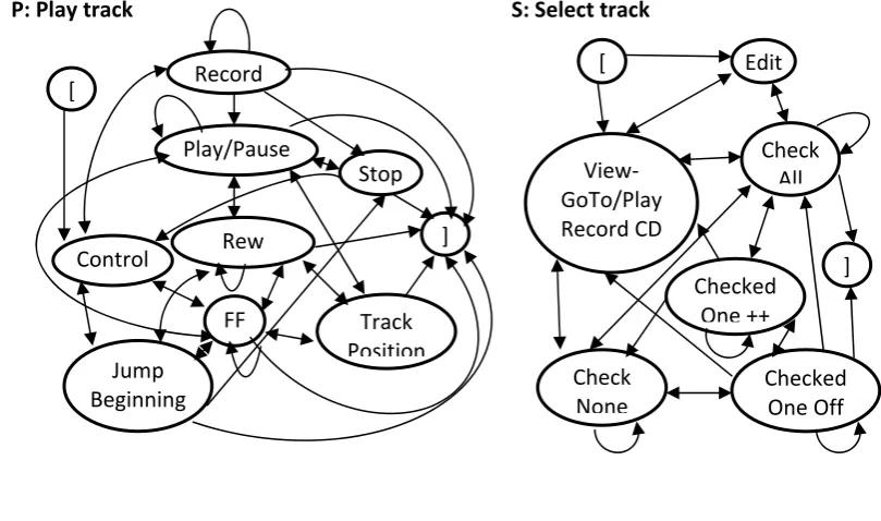
Figure 2.7 shows the refinement of the vertices S, P, and M of the ESG in Figure 2.5
[ Edit
View‐
GoTo/Play
Record CD
Check All
Checked One Off Checked
One ++
Check
None
] S: Select track
P: Play track
[ Record
Graphic User Interface Modelling and Testing Automation
Figure 2.7 Refinement of the vertices S, P, and M of the ESG in Figure 2.4 [56]
Definition 2.15[98]: A Decision Table DT = {C, A, R} represents actions that depend
on certain constraints where:
C ≠ Ø is the set of constraints
A ≠ Ø is the set of actions
R ≠ Ø is the set of rules that describe executable actions depending on a certain
combination of constraints.
Decision tables [99] are popular in information processing and are also used for testing, e.g., in cause and effect graphs. A decision table logically links conditions (”if”) with actions (”then”) that are to be triggered, depending on combinations of conditions (”rules”) [100].
[
Control
Shuffle Continuous
Mute Volume
Graphic User Interface Modelling and Testing Automation
Definition 2.16[98]: Let R be defined as in Definition 15. Then a rule Ri ∈R is defined as Ri = (CTrue,CFalse, Ax) where:
CTrue C is the set of constraints that have to be resolved to be “true”
CFalse = C\CTrue is the set of constraints that have to be resolved to be “false”
Ax A is the set of actions that should be executable if all constraints t ∈CTrue are
resolved to be “true” and all constraints f ∈CFalse are resolved to be “false” .
Note that CTrue ∪CFalse = C and CTrue∩ CFalse = Ø under regular circumstances. In certain cases it is inevitable to remark conditions with a don't care (symbolized with a '-' in DT), i.e., such a condition is not to be considered in a rule and CTrue C∪ False⊂ C.
A DT is used to refine data input of GUI’s.
The most important contribution of the ESG to GUI testing is that it takes into account not only the desirable behaviour, but also the undesirable behaviour of a GUI. That is to say, it tests GUIs not only through exercising them by means of test cases which show that the GUI is working properly during routine operation, but also exercising potentially illegal events to verify that the GUI behaves satisfactorily in exceptional situations. However, the ESG model still faces a number of limitations for real GUI automation. The major limitations of the ESG model include:
Graphic User Interface Modelling and Testing Automation
States explosion. With the algorithm proposed in the ESG model, the vertices and states may increase drastically, especially when taking into account of concurrency;
Procuring test oracle information involves intensive labour;
Unable to model events which have uncertain follow-ups events.
2.3.2 Event Flow Graph (EFG) and Event-Interaction Graph (EIG)
The event flow graph (EFG), and its later version, the event interaction graph (EIG) were recently proposed by the team of Professor Atif M. Memon in the University of Maryland [37, 43, 44, 47]. The EFG-based test automation [37] has been claimed to be the first practical GUI automated smoke test. This was followed by research on automated black-box GUI testing. In these researches, the event flow graph (EFG) was proposed as the core-enabling model. In the EFG, each vertex represents an event. All events which can be executed immediately after this event are connected with directed edges from it. A path in the EFG is a legal executable sequence which can be seen as a test case. EFGs can be generated automatically using a tool called GUI Ripping [44]. Traversing an EFG with a certain strategy can generate test cases.
The EFG was first proposed in 2001 [43]. The definition of the EFG is as follows.
Definition 2.17 [37]: An event-flow graph for a component C is a quadruple <V, E, B,
Graphic User Interface Modelling and Testing Automation
1. V is a set of vertices representing all the events in the component. Each vV
represents an event in C;
2. E V V is a set of directed edges between vertices. Event ei follows ej iff ej
may be performed immediately after ei. An edge (vx, vy ) E iff the event represented
by vy follows the event represented by vx ;
3. B V is a set of vertices representing those events of C that are available to
the user when the component is firstly invoked; and
4. I V is the set of restricted-focus events of the component.
In the definition, a GUI component C is an ordered pair <RF, UF>, where RF represents a model window in terms of its events and UF is a set whose elements represent modeless windows also in terms of their events. Each element of UF is invoked either by an event in UF or RF. Figure 2.8 shows an example of an EFG for Notepad.
To generate the test cases automatically, events are classified into 5 groups:
1. Restricted-focus events open modal windows;
2. Unrestricted-focus events open modeless windows;
3. Termination events close modal windows;
Graphic User Interface Modelling and Testing Automation
5. System-interaction events interact with the underlying software to perform some actions.
Figure 2.8 An example of an EFG [37]
Algorithm GetFollows [43]. 1. GetFollows( v: Vertex or Event)
2. {
3. if(EventType(v)=menu-open ){
4. if vB of the component that contains v
Graphic User Interface Modelling and Testing Automation
6. else 7. Return
8. (MenuChoices(v) {v} B (Parent(v)));
9. }
10. if(EventType(v)=system-interaction) return (B);
11. if( EventType(v)=termination)
12. return (B of Invoked component);
13. if (EventType(v)=unrestricted-focus)
14. return (B B of Invoked Model Dialogue)
15. if (EventType(v)=restricted-focus)
16. return (B of Invoked component); 17. }
Figure 2.9 Algorithm GetFollows
To create an EFG automatically, finding the follow-up events of each event is critical. This can be done using an algorithm called GetFollows [37]. Figure 2.9 shows the algorithm GetFollows.
Graphic User Interface Modelling and Testing Automation
performing v, the GUI reverts to the events in B (line 10). If v is a termination event, i.e., an event that terminates a component, then follows (v) consists of all the top-level events of the invoking component (line 12). If the event type of v is an unrestricted-focus event, then the available events are all top-level events of the invoked component available as well as all events of the invoking component (line 14). Lastly,
if v is a restricted-focus event, then only the events of the invoked component are
available.
Since an EFG models all possible event interactions, it cannot be used directly for rapid testing. To effectively generate test cases, a new event-interaction graph (EIG) was introduced in 2005 [37]. System-interaction events are those that interact with the underlying software, including non-structural events and those that close windows. In EIG, only system interaction events are selected. An EIG can be transferred from an EFG.
Definition 2.18: There is an event-flow-path from node nx to node ny iff there exists a (possibly empty) sequence of nodes nj; nj+1; nj+2; …; nj+kin the event-flow graph E such that { (nx, nj), (nj+k, ny)} edges(E) and {(nj+i, nj+i+1) for 0 ≤ i ≤ (k-1) } edges (E) [37].
Definition 2.19: An event-flow-path < n1; n2; . . . ; nk > is interaction- free iff none of
Graphic User Interface Modelling and Testing Automation
Definition 2.20: A system-interaction event ex interacts-with system-interaction event
ey iff there is at least one interaction-free event-flow-path from the node nx (that
represents ex) to the node ny (that represents ey). [37]
The interacts-with relationship is used to create the EIG which contains nodes, one for each system-interaction event in the GUI. An edge in EIG from node nx (that represents ex) to node ny (that represents ey) means that ex interacts-with ey.
An EIG can be converted from an EFG. Algorithm GenerateEIG in Figure 2.10 is used to convert an EFG to an EIG.
Algorithm GenerateEIG [37]
1. Ṅ /* Nodes set of EIG */
2. Ḕ /* Edges set of EIG */
3. GenerateEIG( EFG(N,E))
4. {
5. Ṅ = N;
6. Ḕ = E;
7. For all n ϵ N
8. {
9. Start(n) = { ni | (n, ni) ϵ E, and n ≠ ni }
10. End(n)={ni | (ni, n) ϵ E, and n ≠ ni }
11. }
12. For all n ϵ N
13. {
14. If( EventType(n)≠System-interaction)
15. {
16. For all nxϵ end(n)
17. For all nyϵ start(n)
18. {
19. Ḕ = Ḕ∪ (nx, ny)
20. If (nx≠ ny)
21. {
22. Start(nx) = start (nx) ∪ {ny}
Graphic User Interface Modelling and Testing Automation
25. }
26. For all nxϵ end(n)
27. Remove n from start(nx)
28. For all nyϵ start(y)
29. Remove n from end(ny)
30. Remove n from Ṅ
31. Remove all edges(n, ni) from Ḕ
32. Remove all edges(ni, n) from Ḕ
33. }
34. }
35. }
Figure 2.10 Algorithm GenerateEIG
The algorithm GenerateEIG takes as input an EFG, represented as a set of nodes N and a set of edges E. It removes all non-system-interaction event nodes and their associated edges from the given EFG. At the termination of the procedure, the event-interaction graph is obtained, represented as a set of nodes Ṅ and a set of edges Ḕ. Ṅ and Ḕ are initialized to N and E (lines 5-6). When traversing all edges of the EFG, a list of nodes start (n) on the edges that start from the node n (except itself) is obtained for all nodes.
Similarly, a list of nodes end (n) that end with the node n (except itself) for all nodes (lines 9-10) is computed. For each node n of the EFG (line 12), all new edges (nx, ny) are added to Ḕ if there is an interaction-free path < nx; n; ny > in the EFG (lines 14-19); start(nx) and end(ny) are updated to add ny and nx in the lists, respectively, if nx and
ny are not the same node (lines 20-23). Accordingly, n is removed from the start and
end lists (lines 26-29). Finally, n is removed from Ṅ (line 30); all edges associated with
n are removed from Ḕ (lines 31-32). The space of event sequences in EIG can be
Graphic User Interface Modelling and Testing Automation
Figure 2.11 EIG for the EFG in Figure 2.7 [37]
Graphic User Interface Modelling and Testing Automation
Regression Tester (DART), and Automatic test oracle generation in regression testing. However, the EFG model still faces a number of limitations. These limitations include:
The EFG cannot model all GUI behaviours. In an EFG, one event has a fixed set of follow-up events. In fact, very commonly, many events such as button clicks may have uncertain follow-up events when the ambient conditions change.
To avoid the explosion of test cases, test case generation with EFG usually reduces the number of test cases by limiting the length of each test case.
Lack of user’s knowledge makes long test cases generation impractical.
The EFG model focuses on events instead of GUI states, which limits the ability of characterizing the full feature of GUIs.
2.4 Conclusion
Graphic User Interface Modelling and Testing Automation
performing mouse clicks, etc. To automatically test GUI based software, various models are used to model the GUI events or states so that test cases generation, oracle information generation, test case execution and evaluation can be automated to some degree. Among the existing models, the event sequence graph (ESG) proposed by Belli and his team [6, 33, 34, 56, 57, 100, 101,102], event flow graph (EFG) proposed by Memon and his team are most popular for GUI testing automation. However, an ESG needs to be generated from an AUT’s specification and the generation of the model involves too much human effort. The EFG is the most practical GUI automation model so far. An EFG can be generated automatically by a tool called GUI Ripping [44]. Both the ESG and EFG models provide basic GUI testing automation, but because the models are all entirely focused on events rather than on GUI states, especially that each event is represented as a node and all the follow-ups are connected to it with directed edges, they are not able to model scenarios in which one event may have uncertain follow-ups.
Graphic User Interface Modelling and Testing Automation
Chapter 3
Graphic User Interface Testing Automation Model
GUIs are very different from conventional command-based interfaces. They present a much more complex structure and more complex event-driven behaviour. GUI testing is laborious, boring, and time and resource consuming. The approaches and tools available to aid the testing process are not satisfactory. As compared to the conventional source code modelling, a proper representation of GUI is needed to model its behaviour.
3.1 What is a GUI?

![Figure 2.4 GUI of Real Juke Box [56]](https://thumb-us.123doks.com/thumbv2/123dok_us/7925963.1315981/50.595.111.529.334.626/figure-gui-of-real-juke-box.webp)
![Table 2.1 Real Juke Box System functions [56]](https://thumb-us.123doks.com/thumbv2/123dok_us/7925963.1315981/51.595.101.528.89.415/table-real-juke-box-functions.webp)
![Figure 2.7 Refinement of the vertices S, P, and M of the ESG in Figure 2.4 [56]](https://thumb-us.123doks.com/thumbv2/123dok_us/7925963.1315981/54.595.221.415.139.345/figure-refinement-vertices-s-p-m-esg-figure.webp)
