© 2014, IJCSMC All Rights Reserved 283 Available Online atwww.ijcsmc.com
International Journal of Computer Science and Mobile Computing
A Monthly Journal of Computer Science and Information Technology
ISSN 2320–088X
IJCSMC, Vol. 3, Issue. 3, March 2014, pg.283 – 290
RESEARCH ARTICLE
DESIGN
OF
HIGH-ACCURACY
FIXED-WIDTH
MODIFIED
BOOTH
MULTIPLIER
1
Ms. Jeena Maria Cherian,
2B.Sireesha
1
Assistant Professor, ECE Department
2
PG Scholar, ECE Department
1,2
Hindustan Institute of Technology and Science Chennai-603 103
1
[email protected], 2 [email protected]
Abstract: The fixed-width multiplier is attractive to many multimedia and digital signal processing systems
which are desirable to maintain a fixed format and allow a little accuracy loss to output data. This paper
presents the design of high-accuracy fixed-width modified Booth multipliers. To reduce the truncation error,
we first slightly modify the partial product matrix of Booth multiplication and then derive an effective error
compensation function that makes the error distribution be more symmetric to and centralized in the error
equal to zero, leading the fixed-width modified Booth multiplier to very small mean and mean-square errors.
In addition, a simple compensation circuit mainly composed of the simplified sorting network is also
proposed. Compared to the previous circuits, the proposed error compensation circuit can achieve a tiny
mean error and a significant reduction in mean-square error while maintaining the approximate hardware
overhead.
Keywords - Modified Booth Multiplier, Booth Encoder, partial product, CSA, Signed-unsigned
1. INTRODUCTION
Many DSP applications and Multimedia, the output data has direct bearing to the accumulation of a
series of products over a single multiplication operation. In those cases, truncation errors results in large output
error, which can be countered by performing additional compensation, which is again dependent on different
© 2014, IJCSMC All Rights Reserved 284
Thus to mitigate such kind of customizations, to decrease the accumulated output error, fixed-width
multipliers with very minute error with simple error compensation circuit [1] are extensively preferred to obtain
more accurate output data.
Through simple error compensation circuit for fixed-width modified Booth multiplier is proposed
which reduces most of the hardware. In order to achieve desired outcome, slight modification of the partial
product matrix of Booth multiplication to reduce the partial product bits in the truncated portion of DTFM is
required. Thereby, we ascertain the correlation between the Booth encoded outputs and the truncated product
error of DTFM is analysed to derive a simple yet effective compensation function, which can result in an
approximation to the carry value generated by truncated portion of DTFM, to reduce the errors result in
truncation and make the error distribution as symmetric and centralized as possible.
Subsequently, developing of simple modified sorting network along with some adder cells as per the
proposed error compensation function. Results derived from implementation and simulation depict that the
proposed fixed-width modified Booth multiplier occupies less area and achieves approximately same accuracy
as PTM which is most accurate existing fixed width modified Booth multipliers in terms of the mean error and
the mean-square error, all of this still by maintaining the approximate Hardware overhead .
The fixed-width modified Booth multipliers can achieve better error performance in terms of the
maximum absolute error and the mean-square error . The smaller mean error and mean-square error represent
that the error distribution is more symmetric to and centralized in the error equal to zero (denoted as zero
error). For many multimedia and DSP applications, the final output data are produced from accumulating a
series of products rather than from a single multiplication operation directly. In such case, the truncation errors
are possibly accumulated to produce a huge output error.
2. CONVENTIONAL MODIFIED BOOTH MULTIPLIER
Multiplication consists of three steps:
1) The first step to generate the partial products;
2) The second step to add the generated partial products until the last two rows are remained;
3) The third step to compute the final multiplication results by adding the last two rows.
The modified Booth algorithm reduces the number of partial products by half in the first step. We used
the modified Booth encoding (MBE) scheme proposed in [2]. It is known as the most efficient Booth encoding
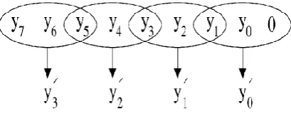
and decoding scheme. To multiply X by Y using the modified Booth algorithm starts from grouping Y by three
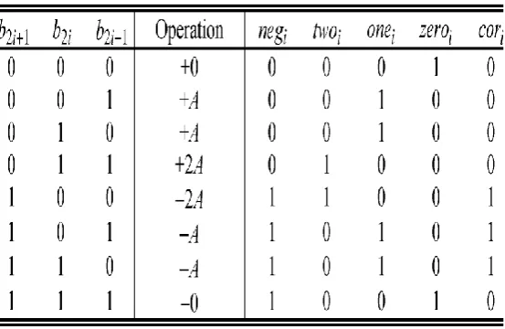
bits and encoding into one of {-2, -1, 0, 1, 2}. Table 1 shows the rules to generate the encoded signals by MBE
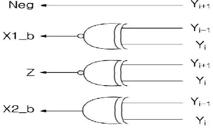
scheme and Fig.1 shows the corresponding logic diagram. The Booth decoder generates the partial products
© 2014, IJCSMC All Rights Reserved 285 Fig 1: Encoder for MBE scheme
Fig 2: Decoder for MBE scheme
Table 1: Truth Table for Booth Encoder
2.1 A TYPICAL IMPLEMENTATION
Booth's algorithm can be implemented by repeatedly adding (with ordinary unsigned binary addition)
one of two predetermined values A and S to a product P, then performing a rightward arithmetic shift on P. Let
m and rbe the multiplicand and multiplier, respectively; and let x and y represent the number of bits in mand r.
1. Determine the values of A and S, and the initial value of P. All of these numbers should have a length equal
to (x + y + 1).
© 2014, IJCSMC All Rights Reserved 286
S: Fill the most significant bits with the value of (−m) in two's complement notation. Fill the remaining (y + 1)
bits with zeros.
P: Fill the most significant x bits with zeros. To the right of this, append the value of r. Fill the least significant
(rightmost) bit with a zero.
2. Determine the two least significant (rightmost) bits of P.
If they are 01, find the value of P + A. Ignore any overflow.
If they are 10, find the value of P + S. Ignore any overflow.
If they are 00, do nothing. Use P directly in the next step.
If they are 11, do nothing. Use P directly in the next step.
3. Arithmetically shift the value obtained in the 2nd step by a single place to the right. Let P now equal this new
value.
4. Repeat steps 2 and 3 until they have been done y times.
5. Drop the least significant (rightmost) bit from P. This is the product of mand r.
3. EXISTING METHOD
The Modified Booth multiplier is an extension of Booth’s multiplier. In Modified Booth, the number of
partial products reduced by N/2, that is half of total partial products as compare to simple multiplication process.
So, clearly if the number of partial products becomes reduced, the area of the multiplier also will reduce and
automatically as the result of it, the speed will increased. So, this multiplier is more efficient.
3.1 MODIFIED BOOTH ENCODER (MBE)
Modified Booth encoding is most often used to avoid variable size partial product arrays. Before
designing a MBE, the multiplier B has to be converted into a Radix-4 number by dividing them into three digits
respectively according to Booth Encoder , Prior to convert the multiplier, a zero is appended into the Least
Significant Bit (LSB) of the multiplier[3]. Table 2 shows the truth table for a Booth encoder. The encoder takes
inputs YN+1, YN and YN-1 from the multiplier bus and produces a 1 or a 0 for each operation: single, double,
negative(X, 2X and Neg).
Fig 3: Grouping of bits for MBE scheme
The operand that is booth encoded is called multiplier, and the other operand is called
multiplicand. If a 3-bit binary input sequence is given at the input, and perform the operation as mentioned in
front of it, the partial products will be generated. As mentioned in figure 3, there are total 3 combinations for
generating a partial product i.e, the obtained partial product is dependent upon the combination of three binary
© 2014, IJCSMC All Rights Reserved 287 Table 2:Modified booth encoding table
Let us consider the multiplication operation of two –bit signed numbers
(multiplicand) and (multiplier). The two’s complement representations of A and B can
be expressed as follows:
(1)
By modified Booth encoding which groups the bits of the multiplier into triplets, can be expressed as
3.2 FIXED-WIDTH MODIFIED BOOTH MULTIPLIER
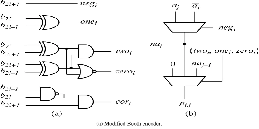
Because the values of partial product bits are heavily dependent on the outputs of Booth encoders[4],
we first explore the relation between the outputs of Booth encoders and the carry value propagated from
to .
Next, an effective and simple error compensation function, which takes the outputs of Booth encoders
as inputs and then generates the approximate carry value, is derived to reduce the truncation error and make the
error distribution as symmetric and centralized as possible. Finally, an uncomplicated and fast compensation
© 2014, IJCSMC All Rights Reserved 288 (a) Modified Booth encoder.
(b) Partial product generation circuit.
Fig 4: Modified booth encoder and Partial product generation circuit
4. PROPOSED METHOD
In the proposed system, the architecture of any one of the booth encoding or partial product generation
is going to be changed accordingly to improve the performance of the system. Compensation error function also
be changed simultaneously.
Booth multipliers are popular due to the reduced elements of the partial products. The fixed-width Booth multiplier with the best accuracy is the post-truncated (P-T) multiplier, which uses rounding off operator after calculating all products. However, the P-T multiplier consumes large silicon area in very large scale integration (VLSI) designs. In order to reduce the area cost, the direct-truncated (D-T) multiplier chops the least significant half partial products directly. Thus a large number of truncation errors occur in the D-T Booth
multiplier.
For this reason, the adaptive compensation methods for fixed-width Booth multipliers are presented to
reduce the truncation errors. In this project a adaptive conditional probability estimator is proposed for fixed
width multiplier that reduce the truncation error and the ACPE is derived from the conditional-probability
theory.
Thus, the ACPE can be easily applied to large length Booth multipliers (such as 32-bit or larger). The
proposed scheme is based on keeping n + w most significant columns of the partial products intact, where w is a
nonnegative integer between 0 and n−1. When w becomes larger the error is smaller, more gates are required in
the compensating circuit. On the contrary, when w is smaller the error becomes larger; fewer gates in the
compensating circuit are needed. Therefore, this algorithm allows users to adjust the value of w according to
their need in the design of the compensating circuit[5], and is thus called adaptive.
When the multiplicand operand is positive and multiplier operand is negative the sign extended bits
should be generated are s_u = 1, a31=0, ,b31= 1, a32= a33 =0, and b32= b33=1. Table 3 shows the SUMBE
© 2014, IJCSMC All Rights Reserved 289 Table 3: SUMBE operation
Sign-unsign Types of operation
0
1
Unsigned multiplication
Signed multiplication
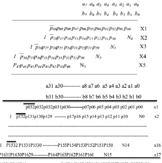
There are 17-partial products with sign extension and negate bit Ni. All the 17-partial products are
generated in parallel and the process is proposed in [8]. In Fig.6 there are 17-partial products namely
X1,X2,X3,X4,X5,X6,X7,X8,X9,X10,X11,X12,X13,X14,X15,X16 and X17. These partial products are added
by the Carry Save Adders (CSA) and the final stage is Carry Look ahead (CLA)[6] adder . Each CSA adder
takes three inputs and produce sum and carry in parallel. There are three CSAs, five partial products are added
by the CSA tree and finally when there are only two outputs left out then finally CLA adder is used to produce
the final result. Assuming each gate delay an unit delay, including partial product generator circuit delay, then
the total through the CSA and CLA is 15+16 = 31 Unit delay.
Fig. 5. 8×8 multiplier for signed-unsigned number.
© 2014, IJCSMC All Rights Reserved 290 5. RESULTS AND OBSERVATIONS
6. CONCLUSION
In this paper, we present a 32-bit×32-bit advanced multiplier capable of carrying out both signed and
unsigned operations. The proposed unified signed/unsigned multiplier was optimized in terms of speed, power
consumption and silicon area by exploiting more regular partial product array, developing more efficient
compression methods and combining several types of fast adders.
REFERENCES
[1] J. M. Jou, S. R. Kuang, and R. D. Chen, “Design of low-error fixed width multipliers for DSP applications,”
IEEE Trans. Circuits Syst. I, Exp. Briefs, vol. 46, no. 6, pp. 836–842, June 1999.
[2] W. –C. Yeh and C. –W. Jen, “High Speed Booth encoded Parallel Multiplier Design,” IEEE transactions on
computers, vol. 49, no. 7, pp. 692-701, July 2000
[3]Jou, S. J., Tsai ,M.-H., and Tsao, Y.-L., “Low-error reduced-width Booth multipliers for DSP applications,”
IEEE Trans. Circuits Syst. I, Fudam.Theory Appl., vol. 50, no. 11, pp. 1470–1474, Nov. 2003.
[4] Wang, G., “A unified unsigned/signed binary multiplier”, TheThirty-Eighth Asilomar Conference on
Signals, Systems andComputers, 2004, Vol. 1, pp.:513 - 516, Nov 7-10, 2004.
[5]Juang, T. B., and Hsiao, S. F., “Low-error carry free fixed-width multipliers with low-cost compensation circuits,” IEEE Trans. Circuits Syst.II, Exp. Briefs, vol. 52, no. 6, pp. 299–303, Jun. 2005.
[6]Huang, H. A., Liao, Y. C., and Chang, H. C., “A self-compensation fixed width Booth multiplier and its
128-point FFT applications,” in Proc.IEEE Int. Symp. Circuits Syst., 2006, pp. 3538–3541.
[7]Song, M.A., Van, L.D., and Kuo, S.Y., “Adaptive low-error fixed width Booth multipliers,” IEICE Trans.
Fundamentals, vol. E90-A, no.6, pp. 1180–1187, Jun. 2007
[8]Li ,C. Y., Chen, T. Y., Chang, C. Y., and Chen, J. N. , “A probabilistic estimation bias circuit for fixed-width Booth multiplier and its DCT applications,” IEEE Trans. Circuits Syst. II, Exp. Briefs, vol. 58, no. 4,pp. 215–