IJEDR1402180
International Journal of Engineering Development and Research (www.ijedr.org)2417
Experimental Parametric Study of Corrugated Wire
Mesh Laminates using Taguchi Design of
Experiments
1
Tushar Kavatkar
2Milind kirkire
Department of Mechanical Engineering1,2Finolex Academy of Management and Technology, Ratnagiri, Maharashtra, India
1 [email protected], 2 [email protected]
Abstract - Corrugated Wire Mesh Laminate (CWML) is manufactured by bonding several layers of metallic corrugated
wire meshes on top of each other. Due to their open structure and the mechanical properties of the parent material, CWML can offer high stiffness and strength per unit weight. Therefore, they have many potential applications where lightweight and high rigidity and strength are required, such as core material in sandwich constructions in mechanical and aerospace engineering, and orthopedic implants in biomedical engineering. The main loading in such applications is transverse compression, occasionally accompanied by in-plane shear. The strength of CWML depends on the several geometrical parameters involved in the configuration of structure. The objective of this paper is to determine the effect of geometrical parameters like corrugation angle, laminates structure and number of corrugated layers on the strength of CWML. For this purpose, samples of CWML are produced in the combinations of three different levels of corrugation angle, laminates structure and number of corrugated layers. The strength of each structure is recorded by subjecting them to compression test. By applying design of experimentation technique, using Taguchi methodology results have analyzed and optimum levels of each controlling parameters are determined for maximum strength of CWML. The maximum strength of CWML per unit weight is found with corrugation angle of 45°, sandwich laminates structure and three corrugated layers. Values of estimated mean and confirmation gain were found close to each other.
Keywords - Corrugation angle, Laminates Structure, Number of Corrugated Layers, Strength to weight ratio, Taguchi analysis
I.INTRODUCTION
Corrugated Wire Mesh Laminates (CWML) are a relatively new class of synthetic open celled cellular structures that have potential for applications in many fields such as biomedical, aerospace, mechanical and automotive engineering . One of the advantages of cellular structures is that they can have a relatively high fraction of open space and hence a much lower density compared to the parent material [1-4]. The earliest fabrication of CWML was reported by Sypeck in 2002 although research into the use of corrugated meshes for mechanical engineering applications, such as heat exchangers, started as early as 1994 [1]. Sypeck et al. [5,6] developed methods of fabricating CWML using 304 stainless steel corrugated wire meshes bonded together using transient liquid phase (TLP) bonding materials. While these methods provide good means of fabricating corrugated wire mesh laminates, they have the disadvantage of requiring a very high fabrication temperature, in the range of 800°C- 900°C. Jeongho Choi et al. [1] developed a new method of fabrication of CWML which has a working temperature of about 225°C. Starting with commercially available woven wire mesh as the raw material, CWML is fabricated by bonding together several layers of the woven wire mesh after they are put through a die and punch arrangement to create corrugations in them. The corrugations provide the layers with high rigidity and bending stiffness in the direction perpendicular to the corrugations. CWML offers the advantage of controllable rigidity and strength [1]. In aerospace and mechanical engineering fields, CWML has potential for applications as high strength, low weight, core material in structural sandwich construction. In these, as well as in use as orthopedic implants, it is the transverse (normal to the plane of the mesh layers) stiffness and load carrying capacity of the CWML that are properties of main interest [1]. In order to find maximum strength of CWML under compressive loading number of experiments can be performed for different combinations of operating parameters and their optimum values can be found out. By applying design of experimentation (DOE) approach we can reduce the number of experiments required without affecting the results. Taguchi's simple, effective and systematic approach helps to find optimal CWML parameters which is not only a reliable tool to find optimize solution but also helps to reduce experimental efforts.
II. METHODOLOGY
2.1 Selection of control factors
IJEDR1402180
International Journal of Engineering Development and Research (www.ijedr.org)2418
created using the same base angle. The selected signal factors in this study are corrugation angle, laminates structure and number of corrugated layers while noise factors are surrounding temperature, moisture content in air, acidic environment, humidity etc which often cannot be eliminated and causes variation in the output. The repeatable and uniform corrugations are obtained if sheets are prepared using 45° triangular profile [8]. Hence levels of corrugation angles (φ) taken were 40°, 45°, 50° and below these range load carrying capacity of CWML structure decreases and above the range there are chances of breaking wire mesh at the centre of corrugation as well as weight also increases. Typically, alternating layers of the CWML are arranged orthogonally so that the high stiffness provided by the corrugation is available in both directions [1]. Hence levels of laminates structure taken were sandwich, orthonormal and orthogonal. For a given wire diameter, minimizing the number of layers or the number of corrugation waves is likely to make structure less capable of carrying load. Therefore, from the point of view of increasing mechanical strength and stiffness, it may be desirable to have multiple layers of wire mesh with multiple corrugations in each layer and on the other side increasing no of layers increases the weight of the structure. Since our aim is to obtain a high strength light weight structure number of corrugated layers were selected as 2, 3 and 4 as shown in table 1.2.2 Fabrication
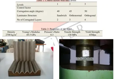
The fabrication of Corrugated Wire Mesh Laminates is a complex process. The Starting material is a plain or woven wire mesh. The first step in the fabrication of CWML is to create the corrugations, which is done by subjecting the plain mesh to a die and punching process. Single layers of the corrugated mesh are then cut to size and arranged in their desired sequence of lamination. The final and major step in the fabrication process is the bonding of the different layers of the CWML to each other using techniques such as welding, adhesive bonding, brazing or soldering which involve high temperature processing [4]. The wire mesh used in the current study is a woven mesh made of 6063 aluminum alloy commonly used as core material for lightweight sandwich constructions in mechanical, automotive, marine and aerospace engineering having wire diameter 0.38 mm with aperture 1.4 mm. The mechanical properties of the material are given in table 2. The bonding material used in the present work is, Araldite Standard Epoxy adhesive. The die and punch which was designed and manufactured under this project work is shown in Figure 1.The plain wire mesh is fed through this pair of die and punches to create corrugations in them. The samples of corrugated wire mesh laminates were prepared according to the combination given in Taguchi’s L9 orthogonal array. Some samples of CWML fabricated using the present technique is shown in figure3.
Table 1: Control factors with their levels
Levels 1 2 3
Control factor
Corrugation angle (degree) 40 45 50
Laminates Structure Sandwich Orthonormal Orthogonal
No of Corrugated Layers 2 3 4
Table 2: Properties of AL 6063
Density Young’s Modulus Poisson’s Ratio Tensile Strength Yield Strength
2700 kg/m3 69.5 GPa 0.3 130 MPa 65Mpa
IJEDR1402180
International Journal of Engineering Development and Research (www.ijedr.org)2419
Figure 3: a) Sandwich structure b) Orthogonal structure c) Orthonormal structure
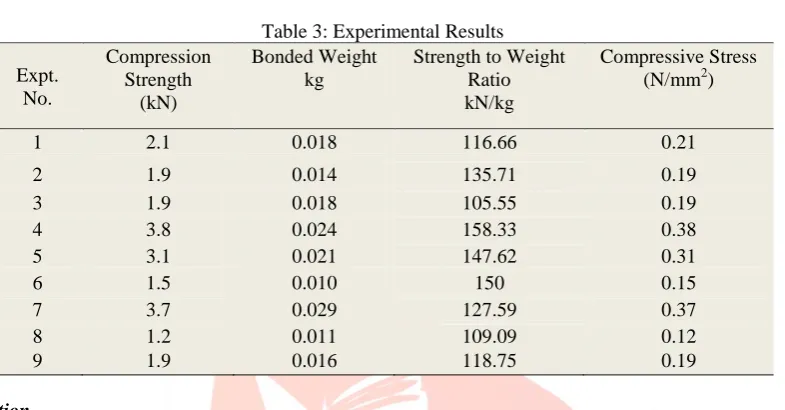
Table 3: Experimental Results Expt.
No.
Compression Strength
(kN)
Bonded Weight kg
Strength to Weight Ratio kN/kg
Compressive Stress (N/mm2)
1 2.1 0.018 116.66 0.21
2 1.9 0.014 135.71 0.19
3 1.9 0.018 105.55 0.19
4 3.8 0.024 158.33 0.38
5 3.1 0.021 147.62 0.31
6 1.5 0.010 150 0.15
7 3.7 0.029 127.59 0.37
8 1.2 0.011 109.09 0.12
9 1.9 0.016 118.75 0.19
2.3 Experimentation
All the fabricated samples were measured for length, height and width with vernier caliper. The samples were nominally square with a side length in corrugation direction (Lx) and perpendicular direction (Ly) of 100mm by 100 mm respectively and a varying corrugation height (Ho) of about 8.39,10 and 11.91 mm according to different corrugation angles and had five corrugation waves in each wire. Diameter of wire (d) and opening width (w) of wire mesh selected is 0.33 mm and 1.43 mm. The nine samples of corrugated wire mesh laminates with three different combinations of corrugation angle, laminates structure and no of layers were tested. Compression test of each specimen of corrugated wire mesh laminates was conducted at room temperature using universal testing machine (INSTRON) manufactured by Fine spavy associates and engineers pvt.ltd having 60 KN maximum load as shown in Figure 2. Compressive load is recorded for every specimen is shown in Table 3. Bonded weight is measured using electronic weighing machine in kg , strength to weight ratio is calculated by dividing compressive load by bonded weight and the compressive stress is the compressive load divided by the area, which is length multiplied by width of structure. III.RESULT ANALYSIS
IJEDR1402180
International Journal of Engineering Development and Research (www.ijedr.org)2420
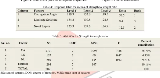
Figure 4: Main effect plots for strength to weight ratio Figure 5: Percent contributionTable 4: Response table for means of strength to weight ratio
Column Factors Level 1 Level 2 Level 3 Delta Rank
1 Corrugation Angle 119.3 152.0 118.5 33.5 1
2 Laminate Structure 134.2 130.8 124.8
9.4 3
3 No of Layers 125.3 137.6 126.9 12.3 2
Table 5: ANOVA for Strength to weight ratio
Sr. no. Factor SS DOF MSS F Percent
contribution
1 CA 2191 2 1096 7.46 75.79%
2 LS 137 2 69 0.47 4.73%
3 NL 269 2 135 0.92 9.31%
4 ERROR 294 2 147 10.16%
5 TOTAL 2891 8 100
SS; sum of squares, DOF; degree of freedom, MSS; mean sum of squares
3.1 Estimation of mean
Once the optimal combination of process parameters and their levels was obtained, the final step was to verify the estimated result against experimental value. Estimated value of all the responses at optimum condition was calculated by adding the average performance to the contribution of each parameter at the optimum level using the following equation [9].
Estimated strength by weight ratio at optimum condition is computed by using the relation
̂ = ̅̅̅̅ + ̅̅̅̅ + ̅̅̅̅ - 2̅ (1)
Where ̂ is estimated mean value and ̅̅̅̅, ̅̅̅̅ and ̅̅̅̅ are the average values of the strength to weight ratio of CWML respectively. Table 6 shows predicted strength to weight ratio calculated using relation 1.
Table 6: Expected strength by weight ratio at optimum condition Grand Average Corrugation
Angle
Laminate Structure
No of Corrugated Layers
Estimated strength
̅ ̅̅̅̅ ̅̅̅̅ ̅̅̅̅
129.92 151.98 134.19 137.60 163.93
Table 7: Comparison of Experimental, Estimated and Regression equation results
3.2 Regression Analysis
The regression equation is [10]:
75.79% 4.73%
9.31% 10.16%
Corrugation Angle
Laminates Structure
No of corrugated Layers
Error
SR NO Response Estimated Value Observed Value Regression 1 Strength to Weight
Ratio(kN/kg)
IJEDR1402180
International Journal of Engineering Development and Research (www.ijedr.org)2421
STRENGTH/WEIGHT RATIO = 141 - 0.08 x - 4.71 y + 0.84 z (2)Where the response is strength to weight ratio in the present work case and x, y, and z are the notations for factors corrugation angle, laminates structure and no of layers respectively. Table 7 shows comparison of predicted value, observed value and regression gain which were found close to each other.
3.3 Confidence Interval
The confidence interval (CI) for predicted results can be calculated by using following expression [9].
C. I. = ±√ ) ) (3) Where F (1, n2) is the F value from F table at a required confidence level at DOF 1 and error DOF n2.Ve = error variance. Ne = Effective number of replications
=
Using these equations confidence interval for all responses is calculated which is shown in Table 8. The F value is taken for 95% of confidence.
3.4 Confirmation Experiment
Three confirmation experiments were conducted at optimum levels of control factors and its average is given in Table 8 even though optimal combination of parameters and their levels coincidently match with one of the experiments in the Orthogonal Array for obtaining better results. Estimated and observed values of each response are tabulated in Table 7 from which it is clear that the observed results are falling within the confidence interval of predicted results hence the confirmation experiment has validated the results.
Table 8: Comparison between Experimental Results and Predicted Results
Sr. No. Response Predicted
Results
Confidence Interval (C. I.) Observed Results
Lower Upper
1 Strength to weight ratio 163.93 111.78 216.08 162.5
IV.CONCLUSIONS
The effect of different parameters on the strength of CWML was studied in this paper. It was found that all the three parameters have strong influence on the strength of CWML. After performing experimental tests on CWML samples and analyzing the results using Taguchi's technique and analysis of variance (ANOVA), following is the conclusions from the present study:Statistically designed experiments based on Taguchi methods were performed using L9 orthogonal arrays to analyze the compression strength of CWML as response variable. The influences of corrugation angle, laminates structure, and the number of corrugated layers on these response was established. Mean and ANOVA both have given similar results which are verified by confirmation experiment.
The optimum levels of the corrugation angle, laminates structure and no of corrugated layers were established for obtaining maximum compressive strength in corrugated wire mesh laminates. The maximum compressive strength with minimum weight is obtained at corrugation angle of 45°, sandwich laminate structure and three corrugated layers .The most dominating factor in CWML structure for strength to weight ratio is corrugation angle with percent contribution of 75.79 %.
Confirmation tests were performed for verifying the estimated optimal conditions. Values of estimation mean and confirmation gain were found close to each other.
REFERENCES
[1] Jeongho Choi, Krishna Shankar, Junghwan Lee, Research of elasticity for a corrugated wire mesh. Materials and Design 52 (2013) 78–91.
[2] Jeongho Choi, Krishna Shankar and Murat Tahtali, Mechanical behavior and numerical analysis of corrugated wire mesh laminates, Journal of Mechanical Science and Technology 26 (1) (2012) 73~80.
[3] Jeongho Choi, Krishna Shankar, and Murat Tahtali, Numerical Investigation of Corrugated Wire Mesh Laminate. Hindawi publishing corporation, Journal of engineering .Volume 2013.
[4] Jeongho Choi, Krishna Shankar, Alan Fien, and Andrew Neely. Methods for manufacture of corrugated wire mesh laminates. International Journal of Aerospace and Mechanical Engineering 5:3 2011.
[5] David J. Sypeck and Haydn N. G. Wadley, Cellular metal truss core sandwich structure. [6] David j. Sypeck, Wrought Aluminum Truss Core Sandwich Structures.
[7] R. A. Kishore, R. Tiwari, A. Dvivedi, I. Singh "Taguchi analysis of the residual tensile strength after drilling in glass fiber reinforced epoxy composites", Journal of materials and design (30), 2186-2190, 2009.
[8] M.R.M. Rejab, W.J. Cantwell, The Mechanical Behavior of corrugated core sandwich panels. Composites: Part B 47 (2013).