TRANSMISSION SPECTRA IN FERRITE-SEMICONDUCTOR PERIODIC STRUCTURE
O. V. Shramkova
Institute of Radiophysics and Electronics National Academy of Sciences of Ukraine
12 Academician Proskura Street, UA-61085, Kharkiv, Ukraine
Abstract—The specific features of TE-wave propagation in a structure fabricated by periodic alternating ferrite and semiconductor layers are investigated. Dispersion characteristics of eigenwaves are calculated. The transmission spectra of an electromagnetic wave oblique incident from the uniform medium onto the multilayer periodic ferrite-semiconductor structure is considered. The features of transmission spectra of the structure with periodicity breakdown are studied.
1. INTRODUCTION
The recent advent of artificial electromagnetic materials (metamateri-als) has opened new opportunities for creating the media, which could provide an additional control over the properties of propagating waves. Semiconductor and ferromagnetic materials lie at the heat of current information technology. The periodic layered structures with semi-conductor and ferromagnetic layers combine different physical proper-ties which do not exist in nature and may be promising for obtain-ing magnetic systems in semiconductor electronics and spintronics. These structures can easily change their characteristics in an exter-nal magnetic field. The results of theoretical investigations of space-inhomogeneous magnetic media were presented in [1–9]. It was consid-ered the reflection from the semiinfinite periodically layconsid-ered structure composed of alternating semiconductor and insulator layers [10]. The energy reflection for the case of TE-wave normal incidence on a semi-infinite plane-stratified structure comprising magnet and nonmagnetic dielectric layers was examined in [11]. It was shown that an external
field can be used to control the spectrum and characteristics of reflected waves. The peculiarities in the spectra of bulk and surface electromag-netic waves in a periodic layered ferrite-semiconductor structure in the effective (finely stratified) medium approximation for intrinsic types of waves was studied in [12]. It was shown that ferrite composites have a negative effective refraction index in some microwave frequencies. The periodical metal-ferrite film composite with symmetrical configuration was analyzed in [13]. It was demonstrated that multilayer waveguides composed of ferromagnetic and dielectric materials have the negative effective refraction index for TE- and TM-waveguide mode [14]. The expressions for effective permeability and permittivity were obtained in the long-wave limit. It was shown that in periodic ferromagnet-semiconductor multilayer composite the left-handed behavior is possi-ble [15–17].
In this paper, we derive analytical formulas and perform numerical calculations of the reflection and transmission coefficients for the electromagnetic wave incident onto a finite periodically layered structure composed of the ferrite and semiconductor layers and subjected to an external magnetic field. The external magnetic field is applied parallel to the layers; the waves traveling in the plane normal to the field are considered. It is shown that by analyzing the frequency, angle of incidence, and magnetic field dependences of the above coefficients one can determine the geometrical as well as physical parameters of the layers making up the structure. We look into the peculiarities of transmittivity through the periodic structure with periodicity-violating ferrite layer.
2. STATEMENT OF THE PROBLEM AND BASIC EQUATIONS
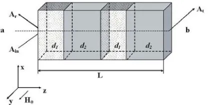
Let us analyze the transmission and reflection of the plane-wave from the magnetoactive periodic structure. Consider a finite periodic structure consisting of alternate ferrite and semiconductor layers (see Fig. 1). We assume that the first layer thickness is d1, whereas the
second layer thickness is d2 (index 1 refers to the ferrite layers and
index 2 to the semiconductor ones). Assume that the thickness of the structure isL(L=N d, whereN is the number of periods,d=d1+d2
is the period of the structure). We introduce a coordinate system such that thexaxis is parallel to the boundaries of the layers and thezaxis is perpendicular to the layers. We suppose that the structure is infinite in thex andy directions. Let the structure be exposed to an external magnetic field H0 parallel to the y axis. Assume the structure to be
placed between homogeneous media with the dielectric permittivities
εa and εb. The incident, reflected and transmitted wave vectors lie in
thexz plane.
Electromagnetic processes in this structure are described by the Maxwell equations and by the equations of continuity and the motion of charge carriers. We seek the variables in these equations in the form of exp(ikxx+ikzz−iωt).
The permeability of ferrite layer is a tensor characteristic for the investigated microwave region. It can be written as [18]
μ|| = μxx=μzz = 1 + ωM
ω2H+ωr2−iωrω
ωH
ω2H+ω2
r−ω2−2iωrω
,
μ⊥ = μxz=−μzx=−
iωωM
ωH2 +ω2
r−ω2−2iωrω ,
where ωM = 2mcπegM, ωH = 2egmcH0, g is the factor of spectroscopic
splitting, M is the saturation magnetization, ωr is the relaxation
frequency. The permittivity tensor for the medium has a diagonal form with componentsεii=εf.
The permittivity tensor of the semiconductor layer can be given as [19]
ε|| = εxx =εzz =ε0
⎡
⎣1− ωp2(ω+iν) ω
(ω+iν)2−ω2 c
ε⊥ = εxz =−εzx=−iε0
ωp2ωc
ω
(ω+iν)2−ω2 c
,
εyy = ε0
1− ω
2 p ω(ω+iν)
.
Hereε0is the part of the permittivity attributed to the lattice,ωpis the
plasma frequency,ωc is the cyclotron frequency, andν is the collision
frequency. The tensor of permeability for nonmagnetic semiconductor is μii = 1. Suppose that the structure is uniform in the y direction.
Then, Maxwell’s equations split into independent equations for two modes with different polarizations. We consider the TE-polarization with components Hx, Hz, Ey. Note that the external magnetic field
affects the TE-wave properties in a ferrite layer only.
The transversal wavenumbers of the layers take the form:
kz1 =
ω2μ Fεf
c2 −kx2, kz2 =
ω2ε yy c2 −kx2,
whereμF =μ||+μ 2 ⊥
μ|| is the effective permeability.
Now consider an infinite periodic structure consisting of alternate ferrite and semiconductor layers. The boundary conditions imply that the tangential electric field component and the normal component of the magnetic induction are continuous at the boundaries between the layers. Using the method of the transmission matrix (which relates the fields at the at the beginning and the end of the period of the structure) and applying the Floquet theorem, which takes into account the periodicity of the structure, we arrive at the dispersion relation:
cos ¯kd = coskz1d1coskz2d2−
1 2
kz1
kz2
1
μF
+kz2
kz1
μF
− kx2 kz1kz2μF
μ⊥ μ||
2
sinkz1d1sinkz2d2. (1)
Here ¯k is the Bloch wavenumber averaged over the period. The analysis of expression for effective permeability reveals 2 characteristic frequencies for magnetic layers: ω1 =
ωH(ωH+ωM) is the frequency
of ferromagnetic resonance (μF →0),ω2 =ωH+ωM is the frequency of
anti-resonance (μ⊥ = 0). From the dispersion Equation (1) we obtain
third characteristic frequency: ω3 =
ω2 H+
ω2M
2 +ωHωM, for which
0.0 1.0 2.0 3.0 4.0 5.0 kxd
ω.
10
-1
0, s
-1
4.8 5.2 5.6 6.0 6.4
ω1
ω3
ω2
0.0 4.0 8.0 12.0
kxd
ω.
10
−1
2, s
-1
1.0 2.0 3.0 4.0
(a) (b)
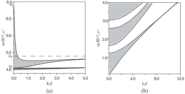
Figure 2. Dispersion dependence for the infinite structure. εf = 5.5, ωM = 3.11·1010s−1,H0= 2000 Oe, ε0 = 17.8,ωp = 1·1011s−1,g= 2, d1 = 0.02 cm,d2= 0.005 cm.
The band structure of the spectrum is depicted in Fig. 2 [17]. For simplicity, we ignore the collision frequency in the semiconductor layers and magnetic damping in the ferrite. The transmission bands are indicated by hatching. It should be noted that close to the frequency of ferromagnetic resonance (ω1) the optical width of the ferrite layers
(kz1d1) tends to infinity. It leads to the fast oscillations of trigonometric
functions in the Equation (1) and to the formation of numerous narrow transmission bands (see Fig. 2(a)). In the frequency region ω1 < ω <
ω2 one transmission band can be highlighted. Forkx → ∞andω→ω3
the width of the band tends to zero. The allowed bands for “dielectric” modes take place above the characteristic frequencies (Fig. 2(b)). In this frequency region the semiconductor layer permittivity and ferrite layer permeability almost are not frequency-dependent.
3. REFLECTION AND TRANSMISSION COEFFICIENTS In this section we present the analytical and numerical investigation of the dependencies of the reflection and transmission coefficients upon parameters of finite periodic ferrite-semiconductor structure.
power ( ˆS = ( ˆm)N):
S11=m11
sinN¯kd
sin ¯kd −
sin (N −1) ¯kd
sin ¯kd ,
S12=m12
sinN¯kd
sin ¯kd ,
S21=m21
sinN¯kd
sin ¯kd ,
S22=m22
sinN¯kd
sin ¯kd −
sin (N −1) ¯kd
sin ¯kd .
(2)
Assume that kx = ωc√εasinθ, the transversal wave numbers for the
homogeneous media are kza = ωc√εacosθ and kzb =
ω
c
2
εb−k2x, θ is the angle of electromagnetic wave incidence. Using the boundary conditions for tangential components of the electromagnetic field at
z = 0 and z = N d, we arrive at the expressions for reflection and transmission coefficients
R=
c
ωkzaS11−
c
ω
2
kzakzbS12+S21−ωckzbS22 c
ωkzaS11−
c
ω
2
kzakzbS12−S21+ωckzbS22
,
T = 2
c
ωkzaexp (−ikzbN d) c
ωkzaS11−
c
ω
2
kzakzbS12−S21+ωckzbS22
(3)
Let us determine the angle of full passage of electromagnetic waves, for which the reflectance is equal to zero. The correspondent incident angle is called the Bruster angle. Assume that the periodic structure is placed into the vacuum εa=εb = 1. In this case|R|2 = 0
(|T|2 = 1) if N¯kd = πq, q = 0,±1,±2. . ., it implies that the Wolf-Bragg resonance takes place; under this condition the layer thickness is equal to an integer number of half-waves.
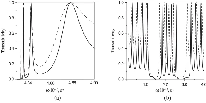
The transmittivity for the finite periodic structure, as a function of the frequency, for different frequency ranges, is shown in Fig. 3. The calculations were performed for 5 periods (N = 5), εa = εb = 1 (i.e.,
the uniform media are vacuum). The solid curves are for θ = π/3 and the dashed curves are for θ = π/6. The dependencies are not monotonous, but the curves are similar. It can be seen that we getN−1 resonant points in each allowed band of the spectrum corresponding to the Brewster’s frequencies.
The band spectrum of periodic structure is determined by the magnetic field strength H0. Therefore, the reflection depends on the
ω.10−10, s-1
0.0 0.2 0.4 0.6 0.8 1.0
T
ra
ns
m
ittiv
ity
4.84 4.86 4.88 4.90
ω.10−12, s-1
0.0 0.2 0.4 0.6 0.8 1.0
T
ra
ns
m
ittiv
ity
1.0 2.0 3.0 4.0
(a) (b)
Figure 3. Transmissivity as a function of the frequency. εf = 5.5, ωM = 3.11·1010s−1,H0= 2000 Oe, ε0 = 17.8,ωp = 1·1011s−1,g= 2, d1 = 0.02 cm,d2= 0.005 cm.
0 1000 2000 3000 4000 5000 H0, Oe
0.0 0.2 0.4 0.6 0.8 1.0
R
ef
le
ctiv
ity
1
2
Figure 4. Reflectivity as a function of an external magnetic field (N = 20).
ω.10−10, s-1
0.0 0.2 0.4 0.6 0.8 1.0
R
ef
le
ctiv
ity
4.88 4.96
4.8
1
2
3
4
Figure 5. Reflectivity as a function of a frequency. θ=π/3,
N = 5, ωr = (1)0, (2)1.06 ·
108s−1, (3)0, (4)1.06 · 108s−1,
1) and ω = 5·1010s−1 (curve 2) and at specified value θ = π/6 are presented in Fig. 4. The magnetic field ranges of 70 Oe< H0 <1550 Oe
(curve 1) and 1300 Oe < H0 < 2075 Oe (curve 2) correspond to the
allowed band for the electromagnetic wave. Outside of these ranges the Bloch wave number is imaginary and, as a result, the trigonometrical functions in (2) transform into the hyperbolic ones, and the reflectivity oscillations do not take place. At frequencies ω > ωp, the reflection is
weakly dependent on the external magnetic field.
Here, we examine how the dissipative processes affect the properties of the reflection and transmission (Fig. 5). Curve 1 corresponds to the nondissipative structure. It can be seen that when the collisions are taken into account, the reflection in the forbidden bands is less than unity, i.e., the energy penetration of the incident wave into the structure occurs. The reason is that the wave numbers of layers kz1,z2 and Bloch wave number ¯kare complex.
Figure 6 shows the reflectivity versus the wave incidence angle. Different figures ((a) and (b)) correspond to the different frequencies. Consider the influence of dielectric permittivities of homogeneous media on the reflectivity and transmittivity of periodic magnetoactive structure. Assume that εa = εb. In the allowed bands (Fig. 6(a))
the reflectivity is seen to increase with the dielectric permittivity of homogeneous media. The penetration of the incident wave increases withεa,b as well (Fig. 6(b)).
(a) (b)
0 0.4 0.8 1.2
Θ, rad
0.0 0.2 0.4 0.6 0.8 1.0
R
ef
le
ct
iv
ity
1 2
0 0.4 0.8 1.2
Θ, rad
0.0 0.2 0.4 0.6 0.8 1.0
R
ef
le
ct
iv
ity
1 2
Figure 6. Reflectivity as the function of an angle of an incident wave.
4. TRANSMISSION SPECTRA OF THE STRUCTURE WITH PERIODICITY BREAKDOWN
Now consider the layered periodic structure with one defect ferrite layer. The parameters of defect ferrite layer do not coincide with those of ferrite layers forming the periodic cell. We assume that the periodicity-violating layer can have another saturation magnetization
MV or frequencyωM V, and another thicknessdV. Let us assume that N1 is the number of the periods at the left of the defect period, and
N2 is the number of the periods at the right of it. The
frequency-dependent transmittivity for θ = π/3 is presented in Fig. 7. The dashed curve is for defectless periodic ferrite-semiconductor structure. The simulation was carried out for a layered structure consisting 14 periods (N = 14) of alternating layers with the following parameters:
εf = 5.5, ωM = 3.11 ·1010s−1, g = 2, ε0 = 17.8, ωp = 1·1011s−1, d1 = 0.02 cm, d2 = 0.005 cm, H0 = 2000 Oe. The frequency range in
Fig. 7 corresponds to the allowed band of defectless periodic structure. The solid curve is for the defect structure that consists of a defect period with periodicity-violating ferrite (εf = 5.5, ωM V = 5·1010s−1
(ω1V = 5,47·1010s−1),g= 2,dV =d1) and semiconductor (parameters
of this layer coincide with the parameters of all semiconductor layers of the structure) layers, N1 = 5, N2 = 8. It can be seen that the
defect structure has the point of full reflectance (|T|2 = 0) close to the frequency of ferromagnetic resonance of defect ferrite layer ω1V. At
frequenciesω1V < ω < ω2V the transversal wave number of defect layer
is purely imaginary (kzV2 < 0), and the electromagnetic wave tunnel through the layer. If the penetration depth of this wave is higher as compared to the thickness of the periodicity-violating layer or equal to it, then the defect structure transmittivity differ from that for a defectless periodic system in that it has the additional resonance point. The transmittivity in the resonance point decreases with increasing defect layer thickness.
Consider the case where ωM > ωM V and the frequency of the
ω.10−10, s-1
0.0 0.2 0.4 0.6 0.8 1.0
T
ra
ns
m
ittiv
ity
5.2 5.6 6.0 6.4
4.8 ω1V
Figure 7. The frequency dependence of transmittivity, (ωM < ωM V).
ω.10−10, s-1
0.0 0.2 0.4 0.6 0.8 1.0
T
ra
ns
m
ittiv
ity
4.4 4.6 4.8 5.0
4.2 ω1V
Figure 8. The frequency depen-dence of transmittivity (ωM > ωM V, θ = π/3): N1 = 5 and
N2 = 8 (solid line), N1 = 8 and
N2 = 5 (dashed line).
5. FINE-STRATIFIED PERIODIC STRUCTURE
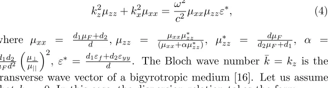
Let us investigate dispersion relation (1) for a fine-stratified medium, i.e., let us assume that kz1, kz2 1. In this case, the dispersion
relation for a fine-layered composite is written as
kz2μzz+k2xμxx= ω2
c2μxxμzzε∗, (4)
where μxx = d1μFd+d2, μzz = μxxμ ∗ zz
(μxx+αμ∗zz), μ∗zz = d2μdμFF+d1, α = d1d2
μFd2
μ⊥ μ||
2
, ε∗ = d1εf+dd2εyy. The Bloch wave number ¯k = kz is the
transverse wave vector of a bigyrotropic medium [16]. Let us assume thatkx= 0.In this case, the dispersion relation takes the form
kz2 = ω
2
c2μ
∗ε∗, (5)
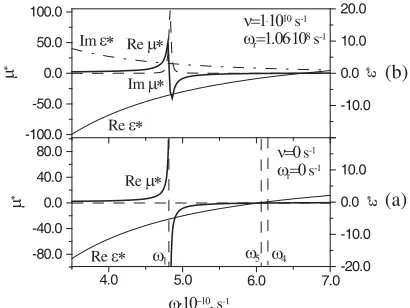
where μ∗ = μxx. Fig. 9 shows how the effective permittivity ε∗ and
effective permeability μ∗ depend on the frequency. In Fig. 9(a), in the
frequency range ω1 < ω < ω4 (ω4 =
ωH+ωMdd1
(ωH +ωM)), the
effective permeability μ∗ is negative. For ω < ω5 (ω5 = ωp √
ε0d2 √
ε∗ < 0. Hence, for ω4 < ω5, in the frequency range ω1 < ω < ω4
we have the composite with the left-handed behavior. To control the left-handed properties of the structure, we should change the external magnetic field. It was considered the influence of dissipative processes on the effective parameters of the ferrite-semiconductor structure (Fig. 9(b)).
ω.10−10, s-1
-80.0 -40.0 0.0 40.0 80.0
μ
∗
-100.0 -50.0 0.0 50.0 100.0
μ
∗
-20.0 -10.0 0.0 10.0 20.0
ε
∗
-20.0 -10.0 0.0 10.0 20.0
ε
∗
5.0 6.0 7.0
4.0
ω1 ω5
Im ε∗
Re ε∗ Re μ∗
Im μ∗
Re ε∗ Re μ∗
ν=0 s-1
ωr=0 s-1
ν=1.1010s-1
ωr=1.06.108s-1
ω4
(b)
(a)
Figure 9. The frequency dependencies of the effective parameters.
εf = 5.5, ωM = 3.11 ·1010s−1, ε0 = 17.8, H0 = 2000 Oe, ωp =
1·1011s−1,g= 2,d1= 0.002 cm, d2 = 0.0005 cm.
The expressions for reflection and transmission coefficients take form
R= kzμxxcoskzL (kza−kzb) +isinkzL
kz2−kzakzbμ2xx
kzμxxcoskzL(kza+kzb)−isinkzL(k2z+kzakzbμ2xx) ,
T = 2e
−ikzbLk
zkzaμxx
kzμxxcoskzL (kza+kzb)−isinkzL(k2z+kzakzbμ2xx) .
(6)
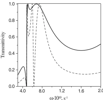
The transmittivity for the finite fine-stratified periodic structure as a function of the frequency is shown in Fig. 10. The calculations were performed for 50 periods (L= 0.125 cm), εa=εb = 1. The solid curve
is for normal incidence (θ= 0) and the dashed one is forθ=π/3. The analysis of formulas (6) for the case of normal incidence allows us to obtain the additional point of full transmittance, when the condition εa = ε
∗
μ∗ takes place. Maximum of the transmittivity
ω.1010, s-1
0.0 0.2 0.4 0.6 0.8 1.0
T
ra
ns
m
ittiv
ity
8.0 1.2 1.6 2.0 4.0
Figure 10. Transmissivity as a function of the frequency. εf = 5.5, ωM = 3.11·1010s−1,H0= 2000 Oe, ε0 = 17.8,ωp = 1·1011s−1,g= 2, d1 = 0.002 cm,d2 = 0.0005 cm, N = 50.
transmittivity for θ = π/3 (dashed curve) corresponds to the case, whereμxx = 0 (ω=ω1 = 4.84·1010s−1 and ω=ω5= 6.31·1010s−1).
6. CONCLUSION
In summary, we have presented the transmission spectra of electromagnetic waves which propagate through a layered periodic ferrite-semiconductor structure. We have studied peculiarities of bulk waves in such a structure. The effect of dissipation in the layers on the reflectivity (transmittivity) of electromagnetic waves has been examined. It has been shown that by analyzing the frequency, angle of incidence, and magnetic field dependencies of the reflectivity or transmittivity one can determine the geometrical as well as physical parameters of the layers composing the structure. The results of our investigations can be used in the implementation of variety of microwave and optical devices.
ACKNOWLEDGMENT
APPENDIX A.
Components of the transfer matrix for one period of the ferrite-semiconductor structure:
m11= coskz1d1coskz2d2−
kz2
kz1
μFsinkz1d1sinkz2d2
+ikx kz1
μ⊥
μ|| sinkz1d1coskz2d2,
m12=i
ω c
1
kz2
coskz1d1sinkz2d2+
μF kz1
sinkz1d1coskz2d2
+i kx kz1kz2
μ⊥
μ|| sinkz1d1sinkz2d2
,
m21=i
c ω 1 μF
−kx2 kz1
μ⊥ μ||
2
+kz1
sinkz1d1coskz2d2
+kz2coskz1d1sinkz2d2−ikx kz2
kz1
μ⊥
μ|| sinkz1d1sinkz2d2
,
m22= −
1
μF
1
kz2
−kx2 kz1
μ⊥ μ||
2
+kz1
sinkz1d1sinkz2d2
+ coskz1d1coskz2d2−i
kx kz1
μ⊥
μ|| sinkz1d1coskz2d2.
REFERENCES
1. Dmitriev V., “2D magnetic photonic crystals with square lattice-group theoretical standpoint,” Progress In Electromagnetics
Research, PIER 58, 71–100, 2006.
2. Abdulhalim, I., “Analytic propagation matrix method for anisotropic magneto-optic layered media,” J. Opt. A: Pure Appl. Opt., Vol. 2, No. 2, 557–564, 2000.
3. Vytovtov, K. A. and Y. S. Tarasenko, “Analytical investigation of one-dimensional magnetoelectric photonic crystals. The 2×2 matrix approach,”J. Opt. Soc. Am. A, Vol. 24, No. 11, 3564–3572, 2007.
5. Vinogradov, A. P., A. V. Dorofeenko, S. G. Erokhin, M. Inoue, A. A. Lisyansky, A. M. Merzlikin, and A. B. Granovsky, “Surface state peculiarities in one-dimensional photonic crystal interfaces,”
Phys. Rev. B, Vol. 74, No. 4, 045128, 2006.
6. Lyubchanskii, I. L., N. N. Dadoenkova, M. I. Lyubchanskii, E. A. Shapovalov, A. E. Zabolotin, Y. P. Lee, and T. Rasing, “Response of two-defect magnetic photonic crystal to oblique incidence of light: Effect of defect layer variation,”J. Appl. Phys., Vol. 100, No. 9, 096110, 2006.
7. Gorobets, Y. and S. Reshetnyak,, “Reflection of spin wave from a ferromagnetic multilayer with interfacial coupling of finite strength (reflection of spin waves from multilayer),” Central
European Journal of Physics, Vol. 6, No. 1, 7–13, 2008.
8. Tkachenko, V. S., V. V. Kruglyak, and A. N. Kuchko, “Spin waves in a magnonic crystal with sine-like interfaces,” J. Magn. Magn.
Mater., Vol. 307, No. 1, 48–52, 2006.
9. Baganas, K., “Inhomogeneous magnetic media: Wave propagation and magnetic permeability reconstruction,” Progress In
Electro-magnetics Research, PIER 46, 313–333, 2004.
10. Bulgakov, A. A. and O. V. Shramkova, “Investigation of reflection coefficient on semiconductor superlattice placed into magnetic field,”Semiconductors, Vol. 34, No. 6, 712–716, 2000.
11. Eliseeva, S. V. and D. I. Sementsov, “Spectrum of natural elec-tromagnetic waves in a periodic ferromagnet-dielectric structure,”
Crystallography Reports, Vol. 50, No. 4, 673–679, 2005.
12. Eliseeva, S. V., D. I. Sementsov, and M. M. Stepanov, “Dispersion of bulk and surface electromagnetic waves in bigyrotropic finely stratified ferrite-semiconductor medium,” Technical Physics, Vol. 53, No. 10, 1319–1326, 2008.
13. Wu, R., “Effective reflection index in periodic metal-ferrite-metal film composite,”J. Appl. Phys., Vol. 97, No. 7, 076105, 2005. 14. Wu, R., T. Zhao, P. Chen, J. Xu, and X. Ji, “Periodic layered
waveguide with negative index of refraction,” Appl. Phys. Lett., Vol. 90, No. 8, 082506, 2007.
15. Tarkhanyan, R. H. and D. G. Niarchos, “Effective negative refractive index in ferromagnet-semiconductor superlattices,”Opt.
Expr., Vol. 14, No. 12, 5433–5444, 2006.
16. Wu, R., T. Zhao, and J. Xi, “Periodic ferrite-semiconductor layered composite with negative index of refraction,” J. Phys.:
Condens. Matter, Vol. 19, No. 2, 026211, 2007
ferrite-semiconductor periodic structure,” Proc. Int. Congress on
Advanced Electromagnetic Materials in Microwaves and Optics,
2008.
18. Gurevich, A. G., Ferrites at Microwaves, Fizmatgiz, Moscow, 1960.
19. Bass, F. G. and A. A. Bulgakov,Kinetic and Electrodynamic
Phe-nomena in Classical and Quantum Semiconductor Superlattices,
Nova Science, New York, 1997.