Available Online atwww.ijcsmc.com
International Journal of Computer Science and Mobile Computing
A Monthly Journal of Computer Science and Information Technology
ISSN 2320–088X
IJCSMC, Vol. 3, Issue. 8, August 2014, pg.737 – 744
RESEARCH ARTICLE
Speech Recognition Module for Home
Automation System Based On ZigBee
B. Muniswamy Naik
1, B. Vamsi Krishna
2MITS COLLEGE, ANGALLU, MADANAPALLI
Abstract : The word “Embedded” itself gives the meaning as the combination of different components are mounted in to a single device, which is also called a system on chip. With the help of VLSI technology it became possible to develop high speed, with low cost, and power efficient and small in size type Integrated Chips. The Micro controller, which is used for this purpose is called IBP (Itty Bitty Processor) or embedded processor due to the fact of its instruction execution speed. The multi task handling system that introduces time delay, which is not at all desirable in any application, in such case, the micro controllers which can play a key role as an embedded system design is more suitable one. Here, we design a generalized embedded system application “voice controlled home appliances” is the evidence for the efficient automation, and is constructed around the microcontroller and VRC is (Voice/speech Recognizer kit). In this the home appliances are controlled according the commands given by the human and the commands are recognized by the speech recognizer and the commands are processed by the micro controller and loads are controlled according to the instructions given to the micro controller by the programmer. These commands are transmitted to the receiver from transmitter through the zigbee wireless communication Zigbee works as a transreceiver here; the commands of our speech are transmitted to the receiver through zigbee from the speech recognizer kit and the controller. The receiver side zigbee will receive the commands from the transmitter and zigbee and then to the controller and loads are operated through these commands.
Keywords - Home automation, Microcontroller, Voice Recognition, ZigBee, Power Supply
I. INTRODUCTION
Controlling The Home appliances by using wireless communication system is an integrated system which is most suitable for the people who belong to senior citizen category and physically handicapped. It is very easy to operate for the controlling of home appliances on the basis of voice commands. The system is portable and configured in a way that is installation, configuration and maintenance is very much easy.
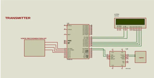
XTAL2 18 XTAL1 19 ALE 30 EA 31 PSEN 29 RST 9 P0.0/AD0 39 P0.1/AD1 38 P0.2/AD2 37 P0.3/AD3 36 P0.4/AD4 35 P0.5/AD5 34 P0.6/AD6 33 P0.7/AD7 32 P1.0/T2 1 P1.1/T2EX 2 P1.2 3 P1.3 4 P1.4 5 P1.5 6 P1.6 7 P1.7 8 P3.0/RXD 10 P3.1/TXD 11 P3.2/INT0 12 P3.3/INT1 13 P3.4/T0 14 P3.7/RD 17 P3.6/WRP3.5/T1 1615 P2.7/A15 28 P2.0/A8 21 P2.1/A9 22 P2.2/A10 23 P2.3/A11 24 P2.4/A12 25 P2.5/A13 26 P2.6/A14 27 U1 AT89C52 D 7 14 D 6 13 D 5 12 D 4 11 D 3 10 D 2 9 D 1 8 D 0 7 E 6 R W 5 R S 4 V S S 1 V D D 2 V E E 3 LCD1 LM016L T1IN 11 R1OUT 12 T2IN 10 R2OUT 9 T1OUT 14 R1IN 13 T2OUT 7 R2IN 8 C2+ 4 C2-5 C1+ 1 C1-3 VS+ 2 VS- 6 U2 MAX232 zigbee TRANSMITTER
VOICE RECOGNISATION KIT
by ZigBee transceiver. The remote system receives the commands through ZigBee transceiver and performs the further operation as per the received signals. The sensors unit is capable of detecting when the user enters or leaves the room by measuring the change in signals strength between the access Point and can accordingly turn on or off appliances such as lights and fans and in the meantime send its status back to base station.
II. System Overview
The home appliances control system consists of both a transmitting station and a receiver station. Each station will be designed separately and with different hardware circuitry.
2.1 Transmitter
The transmitter station will operate with a voltage of +5 volts. This voltage will be used as the r e f e r e n c e operating voltage for all of the circuit components in the transmitter station. The microphone in the transmitter station will be picking up audio in a nearby range. The audio signal from the microphone will be f e d a s input into the HM 2007 speech recognition processor. The HM 2007 processor will process the audio and determines if the commands are speech commands and valid then it will pass the commands in terms of signals through microcontroller and ZigBee to receiver station where the matched command operation will be implemented. A 16 x 2 LCD display module is interfaced with the microcontroller to display the current status of the sensors and relay i s u sed a s con tr ol lin g el em en t t o p er for m swi t ch in g op er a ti on a s ON/ OFF . The HM 2007 processor does voice analysis and identifies on the microphone audio signals. The HM 2007 interfaces directly with a microphone and the microcontroller in turn interfaced with ZigBee transceiver. The word length to be recognized will be selected which can have the highest amount of time duration up to1.92 seconds.
This will allow a maximum of 20 words can be trained and stored within the available memory space of 8KB. This is suitable for th e needs of our product, as the speech command signals will never surpass 2 0 words. Measuring the change in received signals strength between the access Point and can accordingly turn on or off appliances such as lights and fans and in the meantime send its status back to transmitter station.
Figure 1. Handheld microphone with voice recognition unit in the Transmitter
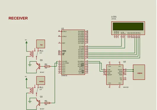
2.2 RECIEVER
XTAL2 18 XTAL1 19 ALE 30 EA 31 PSEN 29 RST 9 P0.0/AD0 39 P0.1/AD1 38 P0.2/AD2 37 P0.3/AD3 36 P0.4/AD4 35 P0.5/AD5 34 P0.6/AD6 33 P0.7/AD7 32 P1.0/T2 1 P1.1/T2EX 2 P1.2 3 P1.3 4 P1.4 5 P1.5 6 P1.6 7 P1.7 8 P3.0/RXD 10 P3.1/TXD 11 P3.2/INT0 12 P3.3/INT1 13 P3.4/T0 14 P3.7/RD 17 P3.6/WRP3.5/T1 1615 P2.7/A15 28 P2.0/A8 21 P2.1/A9 22 P2.2/A10 23 P2.3/A11 24 P2.4/A12 25 P2.5/A13 26 P2.6/A14 27 U1 AT89C52 D 7 1 4 D 6 1 3 D 5 1 2 D 4 1 1 D 3 1 0 D 2 9 D 1 8 D 0 7 E 6 R W 5 R S 4 V S S 1 V D D 2 V E E 3 LCD1 LM016L T1IN 11 R1OUT 12 T2IN 10 R2OUT 9 T1OUT 14 R1IN 13 T2OUT 7 R2IN 8 C2+ 4 C2-5 C1+ 1 C1-3 VS+ 2 VS- 6 U2 MAX232 zigbee RL1 12V vcc Q1 BC547 R1 330 fan RL1 12V vcc Q1 BC547 R1 330 motor RECEIVER
Figure 2. Functional Block Diagram of Remote station Unit
III. Project Design Methodology
Here we w i l l f o c u s o n the principle involved in the design of the Voice Recognition Wireless Home appliance control System Based on ZigBee. The project was divided into partitions to make the design process modular. In the prototype board prepared and fabricated by the authors, the parts replaced with their specifications are:
3.1 voice Recognition Unit: The heart of speech recognition system is HM2007 voice recognition IC processor. The IC can recognize maximum of up to 20 words
3.2 ZigBee: It is a cost effective, power efficient, wireless networking standard serial communication protocol. The cost effectiveness allows the technology to be widely deployed in wireless control and monitoring based applications, the power efficient -usage allows longer life with smaller batteries, and different networking topologies like ad-hoc, mesh ,ring, star provides high reliability and larger range.
3.3 Microcontroller: Any 8-bit microcontroller can be used for configuring this system. Here we have used 8051 micro controller (AT89S52)-full static CMOS controller, with 8k Flash memory and 256 bytes RAM, 4 I/O ports of 8 bit wide, 3 timers/counters along with 8 interrupt sources etc.
3.4 Liquid Crystal Display (HD 162A):16x2 LCD that is 16 characters per row. 3.5 Power supply unit.
3.6 Different sensors relay switches board and sound alarm.
3.1 VOICE RECOGNITION UNIT
The voice recognition system is completely in tegr ated and easy to use programmable speech recognition Circuit. Programmable, in the sense that we can train the words or commands that we want the circuit to be recognized. This circuitry allows us to experiment with many facets of speech recognition technology. It has 8 bit data out which can be interfaced with any microcontroller for further processing and development.
3.1.1 FEATURES • Single CMOS chip.
• Up to 20 word vocabulary of duration length two second each • Multi-lingual
• Non-volatile memory with 3V battery backup which will keep the speech recognition data in memory independent of power. i.e., even after power off.
• Interfacing is very easy with all different controllers like 8051, PIC or AVR can be interfaced to data port.
3.1.2 HM2007
Figure 3.HM2007 MODULE
A 20 isolated word voice recognition system will consists of small external microphone, 4x4 keyboard, 8K Static RAM memory and two 7 segment LED display units along with driver IC’s are combined with a microcontroller, an voice recognition system can be built. It supports two control modes: Manual mode (automatic mode) and CPU mode. It is also available in 48 -pin PDIP package. The pin description of HM2007 is shown above figure.
The keypad and digital display are used to establish communication with and program the HM2007 processor. The keypad is made up of 12 normally open (NO) momentary contact switches. The 74LS373 8-bit registers feature 3- state outputs designed specifically for driving highly capacitive loads or relatively low-impedance loads. The high- low-impedance 3-state and increased high-logic-level drive provide these registers with the capability of being connected directly to and driving the bus lines in a bus-specified system without need for interface or pull-up components. The IC 7448 is BCD to 7–segment converter with common cathode IC. To print the data, we have to convert data from BCD to 7-segment code. The IC will handle this task. It has four inputs called BCD input levels and seven output levels to drive the display. The voice recognition system schematic diagram is shown below in fig.4. A small microphone is connected directly with pin 15(MICIN) of HM2007which is shown below. On this system, voice is trained first and then recognized whenever a command is given through microphone.
The speech recognition system is a completely assembled and easy to use programmable speech recognition circuit. Programmable, in the sense that you train the words (or vocal utterances) you want the circuit to recognize. This board allows you to experiment with many facets of speech recognition technology. It has 8 bit data out which can be interfaced with any microcontroller for further development. Some of interfacing applications which can be made are controlling home appliances, robotics movements, Speech Assisted technologies, Speech to text translation, and many more.
Features:
• Self-contained voice recognition circuitry
• User programmable as per the application
• Up to 20 word vocabulary of duration length two second each
• Supports many languages (Multi-lingual)
• Non-volatile memory back up with 3V battery onboard.
Will keep the speech recognition data in memory even after power off.
• Easily interfaced to control external circuits & appliance.
Specification:
Input Voltage - 9 to 15 volts DC Use a commonly available 12V 500ma DC Adapter Output Data - 8 bits at 5V Logic Level
Applications:
There are several areas for application of voice recognition technology.
• Speech controlled appliances and toys
• Speech assisted computer games
• Speech assisted virtual reality
• Telephone assistance systems
• Voice recognition security
• Speech to speech translation
3.2 ZIGBEE
Zigbee is a wireless serial communication protocol, with the operating frequency of 2.4GHZ it belongs to Industrial scientific and medical (ISM) radio band. There have been a multitude of proprietary protocols for control applications, which bottlenecked interfacing. Need for a widely accepted standard for communication between sensors in low data rate wireless networks was felt. As an answer to this dilemma, many companies forged an alliance to create a standard which would be accepted worldwide.
Before the invention of Zigbee the existing technology for the serial data transfer communication is Bluetooth. but zigbee is most secured method for data transfer due to the fact of Its data spreading technique as DSSS (Direct sequence spread spectrum). Which supports network topologies like star, mesh, clustered and clustered networks. ZigBee has been developed to meet the growing demand for capable wireless networking between numerous low power devices? In industry ZigBee is being used for next generation automated manufacturing, with small transmitters in ever y device on the floor, allowing for communication between devices to a central computer. This new level of communication permits finely-tuned remote monitoring and manipulation.
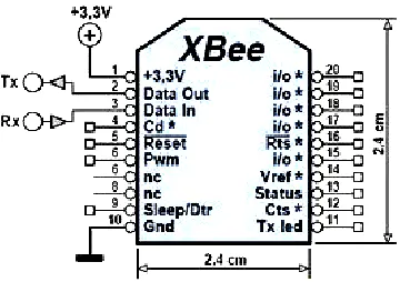
Figure 4. ZigBee pin configuration
The ZigBee and ZigBee Pro radio is made by Digi (formerly Midstream) which is shipped with firmware implementing the IEEE 802.15.4 protocol. These modules use the IEEE 802.15.4 networking protocol for fast point-to-point or peer-to-peer networking. However, the most different part between ZigBee and ZigBee Pro is they have different cover distance range for communicate with own module. ZigBee can be covers around 30m at indoor and 100m at outdoor. Inversely, ZigBee Pro can cover higher distance range than ZigBee which is 100m at indoor and 1500m at outdoor. Both devices that have a UART interface so can be connected directly from microcontroller to pins of RF Module (ZigBee/ZigBee Pro). Using UART interface, we can use this wireless devices to communicate between microcontroller to microcontroller (two 8052’s) or between PC to microcontroller or between PC to PC. Here, we will discuss how to use two ZigBee/ZigBee Pros to interface with microcontroller and how to send command for configuration ZigBee/ZigBee Pro Module. The role of the Zigbee module is to be as transparent as possible. It should be as if a wire was connecting the input to the output and connectivity is never lost.
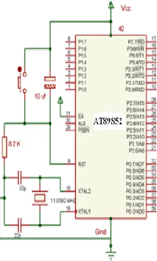
3.3 MICROCONTROLLER 8051
which is minimum necessary clock input. This speed is sufficient for the application. A pin diagram of the AT89S52 is provided in Figure 12.
The inbuilt capabilities of 8052 microcontroller (AT89S52) are
1. T o st or e pr ogr amm in g cod e 8k Flash memory is available 2. Gen er al pur p ose r egi st er st or a g e m em or y 256 bytes RAM 3. 4 I/O ports of 8 bit wide
4. 3 timers/counters of 16 bit wide 5. 8 interrupt sources
6. 26 SFR’s (special function registers) 7. 32 GPIO lines
Figure 5. 8052 Microcontroller with basic connection
3.4 LIQUID CRYSTAL DISPLAY (LCD)
Here we are using a 16 x 2 LCD to display the values on the output screen. It consists 16 pins. Am on g t h em t h e y a r e ca t e g or i z e d i n t o t h r e e wa ys . Fi r st ca t eg or y s u p p l y a n d c on t r a st c on t r o l p i n s 1 , 2 , 3 . S e c on d ca t e g or y r eg i st er c on t r ol p i n s ( R S , R W , E N, p i n s 4 , 5 , 6 r e sp e c t i v el y) a n d t h i r d ca t e g or y i s8 d a t a l i n es ( D0 t o D7 ) . Her e 1 6 x 2 L C D m ea n s we ca n p r in t m a x i m u m o f 1 6 ch a r a ct er s p er l i n e, l i k e wi s e i n t wo l i n e s t o t a l l y we c a n p r i n t 3 2 ch a r a ct er s. Which is sufficient for display output status of any device? RS, R/W and Enable pins of LCD are connected with the receiving end microcontroller port pins. Data lines D0-D7 are connected to one of the output port of microcontroller.
Figure 6. LCD Basic Connection Diagram
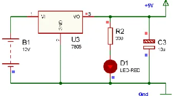
3.5 POWER SUPPLY UNIT
In the power supply unit a simple 9-12V DC battery is connected with the transmitter end as well as receiver end. Because the microcontroller which is the CPU works with regulated +5V power supply so this can be implemented by connecting a 7805 voltage regulator at the output of battery. This is shown in figure 14.
Figure 7. Battery operated +5V power supply
3.6 OTHER COMPONENTS:
A single relay interfacing with microcontroller is shown in circuit below. Her e r el a y i s a n el e ct r om a g n et i c swi t ch , wh i ch con t r ol s swi t ch i n g o f AC l oa d s b y a p p l yi n g DC a s in p ut . Any home appliance operating with A.C voltage levels can be interfaced directly with the relay cir cuit. A buzzer can also be connected by applying +12V at the common terminal of relay.
Figure 8. Relays switch board interfacing with the microcontroller
IV. Scope and Conclusion
Voice recognition Wireless Home appliances controlled system Based on ZigBee is a very useful project for the people like senior citizens and physically handicapped persons, who are unable to do different activities effectively when they are at home and need one’s help to handle those tasks. With the Voice Recognition along with ZigBee network we can minimize the complexity of hardware circuitry in case of wired automation and also it prevent to get up and down again and again to on/off appliances. ZigBee Home Automation provides better operating range as compared to Bluetooth and any other wireless serial communication methods .With the use of ZigBee Home Automation circuit considerable amount of power minimizing is possible and it is compatible with future upcoming technologies so it can be easily customized for individual requirements. On the other hand with voice recognition system, it provides secure access to home. So when we are living in advanced world where everything is changing with in no time such security is mandatory.
References
[1]. Y.Usha Devi 1, II M.Tech, Wireless Home Automation System Using ZigBee, International Journal of Scientific & Engineering Research Volume 3, Issue 8, August-2012 ISSN 2229-5518.
[2]. www.imagesco.com/articles/hm2007/SpeechRecognitionTutorial01.html [3]. Itp.nyu.edu/
[4]. ZigBee Alliance Official Site, [online].Available: www.zigbee.org
[5]. Prof. Jitendra R. Rana, Prof. S.N.Pawar, ZigBee Based Home Automation, http://ssrn.com/abstract=1587245
[6]. “XBee-2.5-Manual,” ZigBee RF communication protocol. (2008). Minnetonka: Digi International Inc. [7]. XBee OEM RF Modules‐ZigBee ‐v1.x1x [2007.06.01] © 2007 Digi International, Inc.www.digi.com [8]. http://www.pyroelectro.com/tutorials/xbee_wireless_interface
[9]. Lakhya1, Inder2, Emanual3, Abhijit4, Lalan5, Debraj6, Er. M. Sujitha7, Home Automation System Based On Arm And Zigbee,
Undergraduate Academic Research Journal (UARJ), ISSN: 2278 – 1129, Volume-1, Issue-3,4, 2012.
[10]. Muhammad A Mazidi , Janice Mazidi , The 8051 Microcontroller And Embedded systems, person Education second Edition ,printed in India by Gopson papers Ltd.
[11]. Dhawan S. Thakur and Aditi Sharma, Wireless Solar Irradiance Meter, International Conference On Re-Newable Energy,5th-6thMay., 2012, Eternal University, H.P., INDIA