Design of a Compact MIMO Antenna for Wireless Applications
Aziz Dkiouak1, *, Alia Zakriti1, Mohssine El Ouahabi2, Asmaa Zugari2, and Mohsine Khalladi2
Abstract—This paper presents a dual-band Multi-Input Multi-Output (MIMO) antenna design with acceptable isolation and compact size for wireless applications. The proposed antenna operates at two frequencies (2.75 GHz–5.3 GHz) and consists of two symmetrical monopoles with a T-shaped junction that is added on the upper layer of the substrate and used to connect the two monopoles and the ground plane. The T-shaped junction is added to enhance the isolation between the two antennas. Different forms of slots have been etched on the ground plane to adapt the frequency bands to the desired frequencies. The simulations and measurement are used to examine the performance of the antenna in terms of S parameters, radiation patterns and the envelope of correlation coefficient. The results show that the MIMO antenna has two resonance frequencies (2.75 GHz and 5.3 GHz), is suitable for WLAN applications and comes with a mutual coupling that is less than 12 dB. As a result, an envelope correlation coefficient lower than 0.001 and a diversity gain higher than 9.98 dB are obtained, which means that the antenna has a remarkable diversity gain at operating bands.
1. INTRODUCTION
The future success of wireless communications systems requires higher data transfer rates, low transmission power and high channel capacity. Multi-Input Multi-Output (MIMO) systems have been introduced to provide reliable high-speed transmissions and to transmit multiple parallel streams in the same frequency channel as compared to traditional Single-Input Single-Output (SISO) systems. Low mutual coupling between different ports of the multiple antennas is pivotal to realize good performance of a MIMO system. Furthermore, excessive mutual coupling will increase the signal correlation between the channels [1].
MIMO systems improve communication performance by using multiple antennas at both the transmitter and the receiver. It is one of many forms of smart antenna technology. Thus MIMO technology has been proposed for different communication systems such as WLAN systems, 3G and 4G cellular mobile systems. Since closely spaced antennas can cause strong mutual coupling, both mutual coupling and isolation can be improved by increasing the distance between the antenna elements. However, the compact size of the wireless devices imposes limitations to this approach. Therefore, the remarked challenge lies in the necessity of reducing the mutual coupling or enhancing the isolation between closely placed antennas’ elements. Many methods have been presented in the literature such as using etched slots on the ground [2], Defected Ground Structure (DGS) [3], including the neutralization line [4], electromagnetic band-gap (EBG) structure [5], using metamaterial structures [6], and etching a slot in each of the feed lines [7, 8].
Several studies have designed a dual-band or multiband MIMO antenna with high port isolation, small size and low envelope correlation coefficient. Qin and Liu [9] have designed a compact dual-band
Received 1 March 2018, Accepted 11 August 2018, Scheduled 21 August 2018 * Corresponding author: Aziz Dkiouak ([email protected]).
MIMO antenna with high port isolation for WLAN applications using DGS method. A dual-band antenna using double T-structure for WLAN applications and a compact wideband MIMO antenna for mobile terminals using slots has been proposed [10, 11].
In this paper, a compact dual-band MIMO antenna with acceptable isolation is proposed. The antenna comprises two symmetrical monopoles and operates at 2.75 GHz and 5.3 GHz frequencies that are suitable for WLAN applications. In order to achieve a low mutual coupling between the two antenna elements, a T-shaped junction [9, 12] is added on the top face of the substrate in order to connect the top face and the ground by via. For a good adaptation, we introduce slots of different forms on the ground plane.
Therefore, we discuss and simulate the parameters of the proposed MIMO antenna such as the reflection coefficient |S11|, the transmission ratio |S12|between two ports,radiation patterns, envelope correlation and diversity gain. The antenna has a compact size of 1.6 mm×38 mm×43 mm and is adapted for WLAN applications. Furthermore, it has a simple structure and is easy in fabrication.
2. ANTENNA & DESIGN
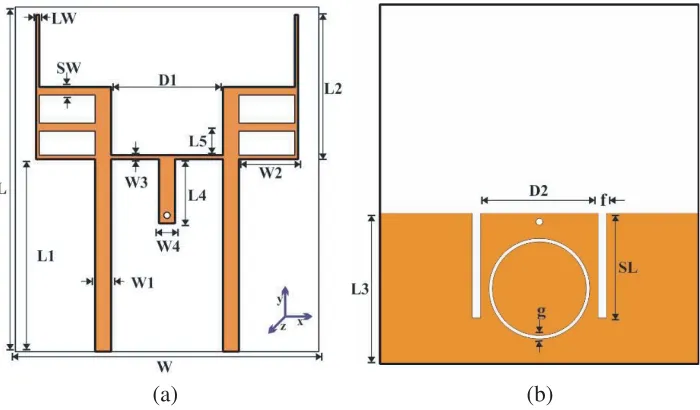
The antenna design is based on an FR-4 substrate with a dielectric constant εr = 4.4, loss tangent δ = 0.02, and thickness of 1.6 mm, with 43 mm in length and 38 mm in width. The geometry of the proposed MIMO antenna is illustrated in Figure 1. It is printed on the top of the substrate and consists of two symmetrical monopoles.
(a) (b)
Figure 1. Geometry of the proposed antenna: (a) top view, (b) bottom view.
The two monopoles are connected by a T-shaped junction on the upper surface of the substrate. On the ground, there is a ring etched on the center of the partial ground between the two slots. The inner and outer diameter of the ring is taken values of 11.2 mm and 12 mm respectively. The top and the bottom are connected by via, in order to improve the isolation and adaptation.
3. PARAMETRIC STUDY
In this section, we present the results of the simulations of the S parameters versus the principal elements of the studied MIMO antenna. Since the antenna has the perfect symmetry (|S11| = |S22| and |S21| = |S12|), we present only |S11| and |S12|. The optimal values of the proposed antenna are presented below in the Table 1.
Table 1. Dimensions of the proposed antenna.
Parameters L W L1 W1 L2 W2 L3 W3 L4 W4 L5 D1 D2 SW F LW SL g
Value
(mm) 43 38 24 2 18 7 18 0.5 6 2 4.5 14 14 1 1 0.4 12.5 0.4
the important geometrical parameters on the reflection coefficient and isolation of the proposed antenna with keeping the dimension values illustrated in Table 1 constant. These parameters are L1, L2, L3, W2,f,SL,D1 andg the thickness of a ring. The simulated results are plotted in Figure 2 to Figure 4.
3.1. Study the Effect Lengths of Proposed Antenna
The simulation results of |S11|with different lengthsL1 are shown in Figure 2(a). It appears clear that as L1 is varied, the lower and upper bands are well adapted at the operating bands. We can see that the best result is obtained for a parameterL1 equal to 24 mm. Similarly, we fixed the other parameters and simulated |S11|for different lengths of L2 and L3. AsL2 increases, the resonance frequency of the upper band is shifted to the desired frequency value Figure 2(b); the considered value is L2 equal to 18 mm.
L = 21 mm
L = 22.5 mm L = 24 mm
(a) (b)
(c) (d)
2 3 4 5 6
Frequency (GHz)
2 3 4 5 6
Frequency (GHz)
2 3 4 5 6
Frequency (GHz)
2 3 4 5 6
Frequency (GHz) 0
-10
-20
-30
-40
|S | (dB)
11
0
-10
-20
-30
-40
|S | (dB)
11
-50
0
-10
-20
-30
-40
|S | (dB)
11
-50
-60 0
-10
-20
-30
-40
|S | (dB)
11
-50
-60
-70
1
1 1
L = 15 mm
L = 16.5 mm L = 18 mm
2
2 2
L = 18 mm
L = 19 mm L = 17 mm
3
3
3 W = 5 mm
W = 7 mm W = 3 mm
2
2 2
AsL3 (length of the partial ground plane) increases, the resonance frequency of the upper band is shifted to the desired frequency value with better adaptation, shown in Figure 2(c). We notice thereby that the best result is obtained for a parameter L3 is equal to 18 mm.
The module of the reflection coefficients with different values W2 is displayed in Figure 2(d). As W2 increases, the resonant frequency of the upper band is affected as well, and it is moved to a desired value, with some little change in the lower band. We observe, thus, that the desired result obtained for W2 parameter is equal to 7 mm.
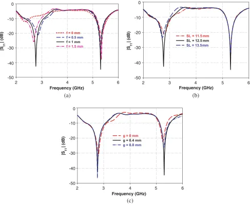
3.2. Tuning of Parameters f, SLand g
In Figure 3(a), we show the simulation of |S11| with different values of larger f of the slot, which is etched in the partial ground plane. It is seen clearly that without the slot (f = 0 mm), the second resonant frequency around 5.3 GHz is affected. Furthermore, a better adaption is obtained at the two bands forf = 1 mm.
f = 0 mm
f = 0.5 mm f = 1 mm f = 1.5 mm
SL = 11.5 mm
SL = 12.5 mm SL = 13.5 mm
g = 0 mm
g = 0.4 mm g = 0.8 mm
(a) (b)
(c)
2 3 4 5 6
Frequency (GHz) 0
-10
-20
-30
-40 |S | (dB) 11
-50
2 3 4 5 6
Frequency (GHz)
2 3 4 5 6
Frequency (GHz) 0
-10
-20
-30
-40 |S | (dB) 11
-50
0
-10
-20
-30
-40
|S | (dB)
11
-50
Figure 3. Simulated|S11|parameter for different values of: (a) f, (b)SL and (c)g.
In Figure 3(c), we can observe that the thickness of ringghas a great influence on the adaptation. With the change of g from 0.0 mm to 0.8 mm, we can see from the figure the desired value obtained with more adaptation for 0.4 mm of g.
3.3. Effect of the Distance D1
In the following section, we display the effect of the distance D1 between the two monopoles on theS parameters, while keeping the other dimensions constant. From Figure 4(a), we show the curves of|S11| with different values of D1. As the distance D1 increases, the lower resonance frequency changes, and the band moves to the desired value for 14 mm ofD1.
D = 13 mm
D = 13.5 mm D = 14 mm
D = 13 mm
D = 13.5 mm D = 14 mm
(a) (b)
2 3 4 5 6
Frequency (GHz) -10
-20
-30
-40 |S | (dB) 11
-50 0
2 3 4 5 6
Frequency (GHz) -10
-15
-20
-25 |S | (dB) 12
-30 -5
1
1 1
1
1 1
Figure 4. Simulated|S12|and |S11|parameter for different values of D1.
On the other hand, Figure 4(b) illustrates the simulated |S12| versus frequency with different values of D1. In this figure, we observe that the mutual coupling decreases when the distance grows from 13 mm to the desired value 14 mm, which means that an acceptable isolation between the elements of the studied antenna is obtained at the operating bands.
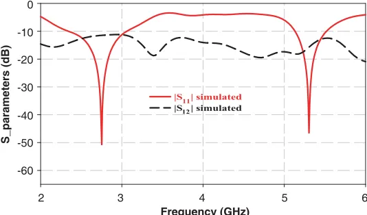
Finally, based on the parametric study of the proposed antenna, Figure 5 shows the simulated results of the MIMO antenna with optimal dimensions illustrated in Table 1.
|S | simulated
|S | simulated
2 3 4 5 6
Frequency (GHz) 0
-10
-20
-30
-40
S_parameters (dB) -50
-60
11 12
According to Figure 5, the reflection coefficient |S11| is adapted to the desired frequencies bands (2.75 GHz–5.3 GHz), with 51 dB to the lower band and 47 dB to the upper band. The impedance bandwidths are about 700 MHz (2.35 GHz–3.05 GHz) and 390 MHz (5.12 GHz–5.51 GHz). The maximum obtained isolation is almost 12 dB at 2.75 GHz and 15 dB at 5.3 GHz indicating good performance of the studied MIMO structure.
4. FABRICATION AND MEASUREMENT
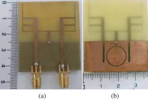
In order to validate the simulated results, we have fabricated and tested the proposed MIMO antenna. The fabrication process is carried out at AbdelMaleKEssaˆadi University Laboratories. It is done using a printed circuit board (PCB) milling machine: The LPKF Protomat E33.
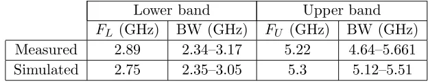
Figure 6 shows photographs of the fabricated antenna. TheS-parameters of the dual-band MIMO antenna are measured by a Rohde and Schwarz ZVB 20 vector network analyzer. For a convenient comparison, the measured and simulated results of the proposed antenna are plotted in Figure 7 and listed in Table 2. Since the two monopoles are symmetrically placed, only |S11| and |S12| curves are given. We can deduce thereby that the antenna (Figure 6(a)) generates two resonant modes around 2.75 and 5.3 GHz (Figure 7). In addition, the measured isolation is higher than 20 dB in both lower and upper bands, indicating a good MIMO performance of the structure.
The measured impedance bandwidths are about 0.83 GHz (2.34–3.17 GHz) resonated at 2.89 GHz,
(a) (b)
Figure 6. Prototype of the proposed antenna: (a) top view, (b) bottom view.
|S | Measured
|S | Simulated
2 3 4 5 6
Frequency (GHz) 0
-10
-20
-30
-40
S_parameters (dB) -50
-60 12
11
|S | Measured
|S | Simulated
11 12
Table 2. Measured and simulated impedance bandwidths of the proposed dual-band MIMO antenna.
Lower band Upper band
FL (GHz) BW (GHz) FU (GHz) BW (GHz) Measured 2.89 2.34–3.17 5.22 4.64–5.661
Simulated 2.75 2.35–3.05 5.3 5.12–5.51
and 1.02 GHz (4.64–5.66 GHz) resonated at 5.22 GHz, which can be used for WLAN bands. The measured results correspond with the simulation ones, but some discrepancies have occurred, due to the fabrication inaccuracy and the conditions of measurement.
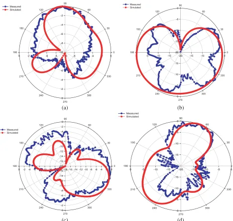
The far-field radiation patterns in E-plane (XZ-plane) and H-plane (XY-plane) of the MIMO antenna were measured. Because of symmetry, the antenna was only measured when port one is exited and other port terminated with a 50 Ω load. The simulated and measured radiation patterns at frequencies 2.75 GHz and 5.3 GHz are presented in Figure 8. The discrepancy between the measured and simulated results of radiation pattern comes principally from the condition of measurement.
5. ENVELOPE CORRELATION & DIVERSITY GAIN
The envelope correlation [13] is an important coefficient which indicates the independence of signals received by antennas. For N antenna system, the envelope correlation of the MIMO system is shown by Equation (1):
ECC =
N
n=1
Si,n∗ Sn,j
2
k=i,j
1−
N
n=1
Si,n∗ Sn,k
(1)
For a two-antenna system, Equation (1) of the envelope correlation becomes:
ECC = |S
∗
11S12+S21∗ S22|2
1−
|S11|2+|S21|2
1−
|S22|2+|S12|2
(2)
The simulated result for ECC of the proposed antenna is illustrated in Figure 9. The values found for this coefficient are very low at operating frequency bands.
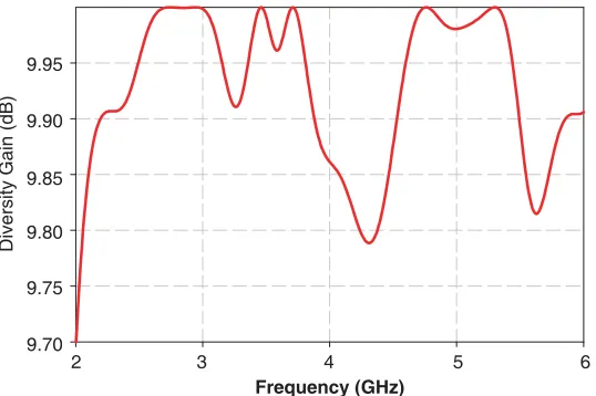
The diversity gain (DG) is the most important characteristic in an antenna diversity system, and it can be obtained from correlation coefficient. The relation between diversity gain and correlation coefficient can be given by the following approximate expression [14].
DG = 10
1− |ρ|2 (3)
whereρ is the complex cross correlation coefficient, with |ρ|2≈ECC.
As can be seen in Figures 9 and 10, a low correlation coefficient and high diversity gain are obtained, indicating that these two antennas are nearly uncorrelated.
6. PERFORMANCE COMPARISON
-10 -8 -6 -4 -2 0 -10 -8 -6 -4 -2 0 -10 -8 -6 -4 -2 0 -10 -8 -6 -4 -2 0 0 30 60 90 120 150 180 210 240 270 300 330 Measured Simulated
-20 -15 -10 -5 0
-20 -15 -10 -5 0 -20 -15 -10 -5 0 -20 -15 -10 -5 0 0 30 60 90 120 150 180 210 240 270 300 330 Measured Simulated
-18 -16 -14 -12 -10 -8 -6 -4 -2 0 -18 -16 -14 -12 -10 -8 -6 -4 -2 0 -18 -16 -14 -12 -10 -8 -6 -4 -2 0 -18 -16 -14 -12 -10 -8 -6 -4 -2 0 0 30 60 90 120 150 180 210 240 270 300 330 Measured Simulated
-20 -15 -10 -5 0
-20 -15 -10 -5 0 -20 -15 -10 -5 0 -20 -15 -10 -5 0 0 30 60 90 120 150 180 210 240 270 300 330 Measured Simulated (a) (b) (c) (d)
Figure 8. Simulated and measured radiation patterns of the proposed antenna at frequencies: (a) E-plane at 2.75 GHz, (b) H-plane at 2.75 GHz, (c)E-plane at 5.3 GHz, (d) H-plane at 5.3 GHz.
Table 3. Performance comparisons of the proposed and reference antennas.
Ref. Size
(mm3)
Band with (GHz)
Isolation (dB)
Permittivity
εr ECC Sub.
Article 43×37×1.6 2.35–3.05 and 5.12–5.51 12 4.4 0.001 FR4
[10] 50×37×0.8 2.20–2.75 and 5.09–5.50 15 3.5 0.1 FR4
[11] 55×50×0.8 UBW 22.5 4.4 − − − FR4
2 3 4 5 6 Frequency (GHz)
ECC
0.020
0.015
0.010
0.005
0.000
Figure 9. The envelope correlation curve.
2 3 4 5 6
Frequency (GHz) 9.95
9.90
9.85
9.80
9.75
9.70
Diversity Gain (dB)
Figure 10. Diversity gain of the MIMO proposed.
7. CONCLUSION
In this paper, we have proposed a compact dual-band MIMO antenna with good performance. The MIMO antenna is characterized by two simple antennas symmetrically placed on an FR4 substrate with a size of 43 mm×38 mm×1,6 mm. To obtain the isolation, a T-shaped junction is used to connect the two monopoles and the ground plane. Through introducing different forms in the partial ground plane, two slots and ring, we achieve a good adaptation. The measured results show that the proposed antenna has an impedance bandwidth of 830 MHz and 1.02 GHz and a low mutual coupling at the two operated bands (2.89 GHz and 5.22 GHz) of less than 20 dB. Moreover, a low envelope correlation of less than 10−3 and a high diversity gain of more than 9.98 dB are obtained. Thus, the proposed MIMO antenna is well adapted for applications in WLAN wireless communications.
ACKNOWLEDGMENT
REFERENCES
1. Chen, S.-C., Y.-S. Wang, and S.-J. Chung, “A decoupling technique for increasing the port isolation between two strongly coupled antennas,”IEEE Transactions on Antennas and Propagation, Vol. 56, No. 12, 3650–3658, 2008.
2. Chiu, C. Y., C. H. Cheng, R. D. Murch, and C. R. Rowell, “Reduction of mutual coupling between closely-packed antenna element,”IEEE Transactions on Antennas and Propagation, Vol. 55, No. 6, 1732–1738, Jun. 2007.
3. Weng, L. H., Y.-C. Guo, X.-W. Shi, and X.-Q. Chen, “An overview on defected ground structure,”
Progress In Electromagnetics Research B, Vol. 7, 173–189, 2008.
4. Wang, Y. and Z. W. Du, “A wideband printed dual-antenna system with a novel neutralization line for mobile terminals,” IEEE Antennas and Wireless Propagation Letters, Vol. 12, 1428–1431, Jun. 2013.
5. Makinen, R., V. Pynttari, J. Heikkinen, and M. Kivikoski, “Improvement of antenna isolation in hand-held devices using miniaturized electromagnetic band-gap structures,”Microwave & Optical
Tech. Lett., Vol. 49, No. 10, 2508–2513, 2007.
6. Lee, Y., H. Chung, J. Ha, and L. Choi, “Design of a MIMO antenna with improved isolation using meta-material,” International Workshop on Antennas Technology (iWAT’11), 231–234, 2011. 7. Yahya, L. S., K. H. Sayidmarie, F. Elmegri, and R. A. Abd-Alhameed, “Arc-shaped monopole
antennas with reduced coupling for WLAN and WiMAX applications,” International Conference
on Internet Technologies and Applications (ITA), 218–223, UK, Sep. 2017.
8. Sayidmarie, K. H., L. S. Yahya, and R. A. Abd-Alhameed, “Crescent-shaped monopoles with reduced coupling for WLAN and WIMAX applications,”Sixth International Conference on Internet
Technologies &Applications, Wales, UK, Sep. 8–11, 2015.
9. Qin, H. and Y.-F. Liu, “Compact dual-band MIMO antenna with high port isolation for WLAN applications,” Progress In Electromagnetic Research C, Vol. 49, 97–104, 2014.
10. Zhao, W., L. Liu, S. W. Cheung, and Y. Cao, “Dual-band MIMO antenna using double-T structure for WLAN applications,” International Workshop on Antenna Technology (iWAT), 2014.
11. Xia, X.-X., Q.-X. Chu, and J.-F. Li, “Design of a compact wideband MIMO antenna for mobile terminals,” Progress In Electromagnetics Research C, Vol. 41, 163–174, 2013.
12. Chen, F.-C., Q.-X. Chu, and Z.-H. Tu, “Design of compact dual-band bandpass filter using short stub loaded resonator,” Microwave and Optical Technology Letters, Vol. 51, No. 4, Apr. 2009. 13. Dama, Y. A. S., R. A. Abd-Alhameed, S. M. R. Jones, D. Zhou, N. J. McEwan, M. B. Child,
and P. S. Excell, “An envelope correlation formula for (N, N) MIMO antenna arrays using input scattering parameters, andincluding power losses,” International Journal of Antennas and
Propagation, Aug. 2011.
14. Iglesias, E. R., “Printed multi-band MIMO antenna systems and their performance metrics,”IEEE
Antennas and Propagation Magazine, Vol. 55, No. 5, 218–232, Oct. 2013.
15. Sharawi, M. S., A. B. Numan, and D. N. Aloi, “Isolation improvement in a dual-bad dual-element MIMO antenna system using capacitively loaded loops,” Progress In Electromagnetics Research, Vol. 134, 247–266, 2013.