Inter-level consistency checking between requirements
and design artefacts
Final Project
MSc Computer Science
Inter-level consistency checking between requirements
and design artefacts
By
M.J. Looise
Final Project
MSc Computer Science
Graduation committee
Prof. Dr. ir. M. Aksit Dr. Ir. K.G. van den Berg A. Gokni, MSc
Dr. I. Kurtev
Chair
Software Engineering
Faculty
Electrical Engineering, Mathematics and Computer Science
University
Abstract
In software development we can identify a number of phases in which a software product is constructed. These phases guide the development from its first conception to realization and maintenance. During these phases, a number of artefacts are created. The artefacts clearly have relations to each other. These relations are bidirectional: a change in, for example, a requirement will impact the architectural design, but also the other way around, changing the architectural design can impact the fulfilment of certain requirements.
It is very important to keep the artefacts consistent. When due to changing circumstances the system needs to be adapted, the requirements of the system will change. Also visa versa, when the architecture is changed, some of the requirements may not be fulfilled any more. In practice, keeping these artefacts in sync with each other is a manual process of reviewing. This is a labour intensive and error prone activity. As a result, the different artefacts can become inconsistent. In order to improve this situation, support for maintaining consistency between requirements and lower level design artefacts in a software development project should be available.
Model Driven Engineering (MDE) techniques can be used to support maintaining this consistency. We propose metamodels for requirements specification and architectural design to explicitly define the structure of these artefacts and to perform consistency checking on them. Metamodels have been derived from a number of research papers, covering requirements and architectural modelling. In composing the requirements metamodel, we only included elements related to the structure of the requirements and its relations to other elements in the requirements engineering process. Elements and relations to artefacts in other design levels are not included. The architectural metamodel is derived from basic components, in an Architecture Description Language (ADL) comparison framework. By performing a case study, we successfully validated these metamodels against concrete instances of requirements specifications and architecture descriptions. This case study checks the conformance of an existing requirement document to the requirements metamodel, and an existing high level design to the architectural metamodel. Using the concepts offered in the metamodels, we can establish trace relations between them.
We propose the use of a separate tracing model to store trace relations between models. A tracing model conforms to the trace metamodel. This metamodel defines typed trace relations with formal semantics. We use interlevel relations, intralevel relations and within-model relations as traces. Currently, two types of interlevel relations are specified in the trace metamodel: the satisfies relation and the refines relation. We use these relations to check the consistency of both a requirement model with respect to an architectural design, and visa versa. The trace model also offers another advantage: the possibility to model relations in a flexible way. It offers an extension mechanism to include other relations as traces. This becomes possible by defining traces as a role of other relations. In order to use the proposed techniques and models in practice, we have developed a tool to ensure consistency between requirements and architectural design. In this tool, interlevel relations can be established between requirements and architectural models. Intralevel relations are established between models of the same type. The tool is designed as an Eclipse plug-in. It uses a translation to Prolog, to allow reasoning about the relations. By using Prolog queries to check the formal semantics of the interlevel relations and intralevel relations, the tool enables the user to check the consistency of a requirement document with respect to a certain design.
In this thesis, we have compared our tool to an existing tool offering tracing of requirements to implementations. We can conclude that the tooling in this thesis offers similar functionality, but with a semantic richer way of defining traces. The typed traces, defined in the trace metamodel, offer richer semantics to be used in consistency checking. It also allows for the extension of the consistency checking mechanism. Existing tooling offers lesser possibilities in this respect.
Preface
The work that lies before you is the final piece of my Computer Science study at the University of Twente. I would like to take this opportunity to thank some of the people that have, directly or indirectly made it possible for me to complete this work.
First of all I would like to very much thank my supervisors during my Master thesis, Ivan Kurtev, Arda Goknil and Klaas van den Berg. They have helped me to stay on course, when sometimes I myself was losing directions.
Especially the steady directions and ideas of Ivan have helped me to structure my project and thesis. I will furthermore always have good personal recollections of our many discussions, also those not related to the project. Your door has always been open for me whenever I needed guidance, which helped me very much. Many times I had great doubts about the project when entering your door, but almost always I left with a feeling that we were still on the right track. I hope that you will continue to do the research you like, even when this is not in the beautiful city of Enschede.
I would also like to thank Arda for his comments and vision on the chapters of this thesis. They have certainly helped to present this thesis in the form it is in now. Also the help of Klaas to keep structure and steady directions in the Master project has helped me greatly. The combination of Ivan’s steady vision, the structure offered by Arda and Klaas has proven a great combination. I couldn’t have asked for a better team of supervisors. Furthermore I would also like to thank the people of Chess, for their time and giving input on my project.
I would of course also like to thank my family and friends to support me during my adventure in the ‘tukker-land’ Twente. It has been a great experience which would not have been possible without the support of all of you.
I would especially like to thank my mother, who guided me towards the opportunity to continue my study, after having already finished my Bachelor study in the beautiful Zeeland. Even when the situation of leaving home has not been easy. I don’t think that I could have finished this study without your support. I would have wished that my father could also have witnessed my graduation on the university. I hope that you will somehow know that I’ve achieved it. I know it would have made you proud.
I would also like to thank my study friends, which motivated to keep going, also in the periods of difficulty, which all of us faced. I will especially remember the many train and car trips together with my fellow ‘Zeeuw’, Wouter. Also will I remember the many projects that I carried out, together with the other Wouter. Lastly I would like to thank my room mates for putting up with me, also in the difficult periods of the master project.
Thank you all for making my master study possible. Atjo!
Martin Looise,
Table of contents
2.1 The need for requirements modelling ... 5
2.2 Current work on Requirements modelling ... 6
2.2.1 REMM Studio ... 6
2.2.2 Model Based Requirements Engineering for the Web... 9
2.2.3 SysML ... 12
2.3. Towards a common requirement metamodel ... 13
2.3.1 Criteria for selecting metamodel elements... 13
2.3.2 Basic requirement concepts... 14
2.3.3 Requirement taxonomy ... 16
2.3.4 Relationships... 18
2.3.5 A Converging common requirement metamodel ... 23
2.3.6 Difficulties in the requirement metamodel and possible extensions ... 25
2.4 Summary... 28
3. Architectural design modelling... 29
3.1 What is Architecture... 29
3.1.1 The importance of architecture ... 31
3.1.2 How to arrive at an architecture, and what to do with it ... 33
3.1.3 Architectural views ... 34
3.3 Towards a common Architectural metamodel. ... 45
3.3.1 Criteria for composing the common architectural model... 45
3.3.2 The suggested architectural metamodel. ... 47
3.4 Summary... 49
4.3.2 Relations in a trace ... 54
4.4 Categorisation of relations ... 58
4.5 Traceability as a role... 60
4.6 Towards a traceability metamodel. ... 61
4.7 The concept of consistency ... 65
4.8 The difficulty in maintaining traceability ... 66
4.9 Summary... 69
5. Validation of the metamodels ... 71
5.1 Validation approach ... 71
5.2 Validation of Requirements metamodel... 72
5.2.1 Description of the requirements model. ... 72
5.2.2 Conformance of the metamodel... 72
5.2.3 Results of the validation ... 74
5.3 Validation of architectural metamodel... 75
5.3.1 Description of the architectural design model ... 75
5.3.3 Results of the validation ... 77
5.4 Summary... 78
6. Tool support... 79
6.1 The Eclipse Rich Client Platform ... 79
6.2 The use of model based frameworks... 80
6.2.1 Model Driven Development with Eclipse... 81
6.2.2 EMF ... 81
6.2.3 GMF ... 81
6.3 The Architecture of the Tracing Toolkit... 82
6.3.1 Top level description ... 83
6.3.2 (Meta) modelling level and editors ... 85
6.4 Fitting it all together... 85
6.4.1 Integration into the Eclipse IDE... 85
6.4.2 Editors for requirements and architectural design models... 86
6.4.3 Storing model information ... 89
6.4.4 Consistency checking ... 90
6.4.5 Achieving consistent models... 90
6.5 Strengths and weaknesses of the Tracing Toolkit... 91
6.5.1 Strengths ... 91
6.5.2 Weaknesses... 93
6.6 Future extensions and improvements... 94
6.7 Summary... 96
7. A comparison with existing tooling... 97
7.1 A comparison framework on traceability tools ... 97
7.2 The Forest Eclipse plug-in ... 99
7.2.1 The Forest repository elements ... 99
7.2.2 The Forest tooling ... 101
7.3 A comparison between the Forest tool and the Tracing Toolkit ... 103
7.3.1 Storage... 103
7.3.2 Trace checking ... 104
7.3.3 Usability... 107
7.3.4 Extendibility ... 108
7.3.5 Scalability ... 109
7.4 Conclusion of the comparison ... 112
7.4.1 Storage... 112
8.3 Research Questions and Answers ... 121
8.3.1 Model Driven Engineering Techniques ... 121
8.3.2 Model requirements and architectural design ... 122
8.3.3 Consistency between requirements and lower level design ... 122
8.3.4 Tool support ... 123
8.4 Future work ... 124
References ... 125
Appendix A. Requirements TMS... 129
Appendix B. Requirements Forest project ... 131
Appendix C. Requirements Tracing Toolkit... 133
Appendix D. Comparison criteria for comparing Forest Tool with the Tracing Toolkit... 135
Appendix E. Screenshot of the Tracing Toolkit ... 137
Appendix F. Example Model Serialisation ... 139
Appendix G. Example Prolog Serialisation... 141
List of figures
Figure 1: REMM metamodel ... 7
Figure 2: Conceptual model [Marshall’03]... 10
Figure 3: Requirements model [Marshall’03]... 11
Figure 4: Three aggregation levels [Wieringa'03]... 16
Figure 5: Refinement of Business and Software requirements... 17
Figure 6: Decomposition example... 20
Figure 7: Requirement / Solution dependency ... 20
Figure 8: Refinement changing and maintaining the original relations ... 22
Figure 9: Common requirement metamodel... 23
Figure 10: The Architecture Business Cycle [Bass’05] ... 33
Figure 11: Conceptual model of architectural description [IEEE1471'00] ... 34
Figure 12: The 4+1 view model ... 36
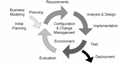
Figure 13: Iterations in the RUP [Noppen’07]... 39
Figure 14: RUP Framework... 39
Figure 15: Synthesis based Software Architecture Design Approach [Tekinerdogan'00]... 41
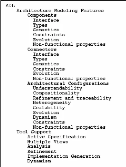
Figure 16: ADL Classification and comparison framework ... 42
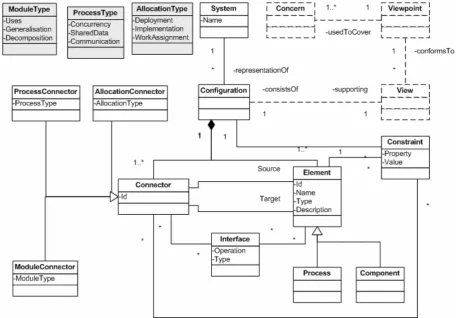
Figure 17: Architectural Metamodel ... 47
Figure 18: Forward and backward traceability[Knethen’02] ... 57
Figure 19: Types of relations ... 59
Figure 20: Trace metamodel ... 61
Figure 21: Satisfies and Refines Combined ... 64
Figure 22: TMS high level Architecture ... 76
Figure 23: Eclipse system Architecture [McAffer et al'06] ... 80
Figure 24: GMF Overview ... 82
Figure 25: Tracing Toolkit architecture... 83
Figure 26: OMG Metalevels: MOF. ... 84
Figure 27: Tracing Toolkit: requirement editor ... 87
Figure 28: Tracing Toolkit: A Wizard for creating a trace model ... 88
Figure 29: Tracing Toolkit, Trace editor ... 88
Figure 30: Delegation in the Forest project ... 100
Figure 31: Forest repository model abstract... 101
Figure 32: Forest Eclipse-plug-in ... 103
Figure 33: Forest trace view ... 111
Figure 34: Generated Trace Matrix in Forest ... 111
List of tables
Table 1: Requirements validation summary ... 75
Table 2: Architectural validation summary ... 78
Table 3: OMG Meta Levels... 84
List of terms
Architecture An architecture of software or a computing system is the structure or structures of the system, which comprise software elements, the externally visible properties of those elements, and the relationships among them [Bass’03]
Requirement A requirement is a condition or capability needed by a user to solve a problem or achieve an objective [IEEE-610’90]
Requirements phase A requirements phase is the period of time in a software life cycle during which the requirements for a software product are defined and documented [IEEE-610’90]
Requirement Engineering Requirements Engineering captures the desired conditions or capabilities needed by a user to solve a problem or achieve a goal he/she has [IEEE-610’90]
Traceability Traceability is the degree to which a relationship can be established between two or more products of the development process, specially products having a predecessor/successor or master-subordinate relationship to one another; for example, the degree to which the requirements and design of a given software component match. [IEEE-610’90]
Interlevel relationship An interlevel relation is a relation between model elements and/or models in different development phases within the same iteration of a software development process [this thesis Chapter 4]
Intralevel relationship An intralevel relation is a relation between model elements and/or models in different iterations within the same development phase of a software development process [this thesis Chapter 4]
List of abbreviations
ABC Architecture Business Cycle
AD Architectural Description
ADL Architecture Description Language
ATAM Architectural Trade-off Analysis Method
B2B Business to Business
CBAM Cost Benefit Analysis Method
COTS Common Of The Shelve
CRM Customer Relation Management
GORE Goal Oriented Requirements Engineering
GUI Graphical User Interface
IDE Integrated Development Environment
JDT Java Development Tools
JRE Java Runtime Environment
KAOS Knowledge Acquisition in autOmated Specification
1. Introduction
In this chapter, the context of this graduation project will be explained. First the background of the project will be sketched in Section 1.1, to give a better understanding of the importance of this project, and why it is carried out. In Section 1.2, the project description will be given. Here we discuss what topics will be included in this study. After this in Section 1.3, the problem statement will be formulated, which will lead us to the research questions. Section 1.4 will describe the approach that we have taken and the topics that will be treated. The scientific contributions of the thesis will be described in Section 1.5. This chapter concludes with an overview of the thesis.
1.1 Project background
In software development, we can identify a number of phases in which a product is constructed. These phases guide the development from its first conception to realization and maintenance. During these phases, a number of artefacts are created. We can identify the following phases in a software development project: business modelling, requirements formalization, architectural design, detailed design and finally the implementation phase. The artefacts that are created during these phases are clearly related to each other. The business domain for example forms the basis from which the requirements are derived. The architectural design is a solution for the requirements. The architectural design components are created to fulfil certain requirements. Usually, these relations are bidirectional: a change in a requirement will impact the architectural design, and also the other way around, changing the architectural design can impact the fulfilment of certain requirements.
This graduation project is carried out in the context of the QuadREAD project (Quality-Driven Requirements Engineering and Architectural Design). The QuadREAD project is joint research project of the Software Engineering Group (TRESE) and the Information Systems Group at the University of Twente and started in December 2006. The QuadREAD project is supported by NWO (Nederlandse organisatie voor Wetenschappelijk Onderzoek) in the Jacquard Programme. The main goal of the QuadREAD project to achieve a better alignment between analysts who state the requirements, and architects who design the architecture. Alignment between these two fields of expertise is important, because they both concern the same system (only from different point of view). Only when the different artefacts are kept consistency with each other, can these also be used in the development and maintenance phases of the software development.
Model Driven Engineering (MDE) techniques can be used to improve the consistency between artefacts. The way of working of MDE, using metamodels as a core concept for the transformation of models, can be used as a mechanism to check consistency. When stable concepts for both requirements and architectural modelling are known, relations between these two models can be established. These (trace) relations should also be captured in a consistent and precise way.
Next to QuadREAD, the Forest project is carried out by Chess, a software development company and a partner in the QuadREAD project. The Forest project aims at improving the traceability of requirements to lower level design artefacts through a decomposition of a system into subsystems. It offers tool support to assist the automated tracing of requirements to lower level artefacts. In this way the company tries to improve the insight in requirement implementation of a system. The tool can indicate the fulfilment of a certain requirement via a trace link to for example code artefacts. Another goal of the Forest project is the generation of requirement documentation
1.2 Project description
possible to model the architecture in a practical way as a part of the state of the practice. Material from current software projects within Chess should provide enough examples from the business domain to validate the models. Special attention need to be paid to the composition of artefacts, and how compositions of artefacts relate to each other.
It should be possible to define relations between artefacts at the requirement level and at the architectural design level. These bidirectional relations should be used to trace changes between the two levels. This can be used to ensure consistency amongst design artefacts. In this project we will focus on maintaining interlevel consistency amongst artefacts. Interlevel consistency checking maintains consistency between elements in models at different development phases. These models are contained within the same iteration of a software development process. The focus will be on consistency between requirements and architectural design.
To show the usability of these concepts in practice, tool support needs to be developed in the form of an Eclipse plug-in. This plug-in should be able to store and retrieve requirements and architectural models and ensure consistency amongst them. To validate the use of these techniques and tools a case study will be carried out with material from Chess.
When we place this research project in the scope of a software development project, it covers both the requirements and the architectural development phase. Both the storing and retrieving of requirement and architectural models will be investigated, in particular maintaining consistency of the interlevel dependencies.
Summarizing, the following topics are studied in this thesis:
• Storing and retrieving early design information, focussed at requirements and architectural design; o Modelling of requirements in a semantic rich manner;
o Modelling of architectural design information;
• Defining consistency between requirements and architectural design; • Implementing the techniques for the maintenance of consistency;
• Designing and implementing tools to support the maintenance of consistency.
1.3 Problem statement
It is very important to maintain the consistency among the numerous artefacts in a software development process. When due to changing circumstances, the system needs to be adapted; the requirements of the system will change. This will often result in a changed architectural design. Also visa versa, when the architecture is changed, the requirements will also be impacted. In practice, keeping these artefacts in sync with each other is a manual process of reviewing. This is however a labour intensive and error prone activity, and as a result the different artefacts can get out of sync (become inconsistent). The result can be that the artefacts no longer represent the actual system. This is of course an undesirable situation. We aim at a situation in which the relation between requirements and lower level design artefacts can be kept consistent in an easy and tool supported way. Summarizing, the problem we want to address in this thesis is the following: It is difficult to maintain the consistency between requirements and design artefacts in a software development project in case of changes. Accordingly, we can formulate the following research question:
How can we improve the consistency between requirements and lower level design artefacts in a software development project in case of changes?
In this graduation project, we will use techniques from Model Driven Engineering (MDE). This leads us to the following sub-questions:
1. Is it possible to model requirements and architectures using Model Driven Engineering techniques, e.g. by using metamodels?
2. Is it possible with these metamodels of requirements and architectural designs to enable
consistency checking?
4. Is it possible to maintain consistency between requirements and architectural design with tool support?
1.4 Approach
To answer the research questions, we first investigate the current work in requirements and architectural models. This allows us to identify the key concepts in both domains. This will be the base for deriving metamodels to support the storing of information in these domains. Once these metamodels are derived, we will validate these models using case studies.
The metamodels will offer a base for deriving trace models that creates relations between requirements and architectures. A trace model will be the key for establishing consistency between requirements and architectural design. By using the relations in the trace metamodel, we can check certain properties of the models connected by a trace model. We will investigate which properties need to be checked before we can conclude that a model is consistent with respect to another model. After having established the concepts to maintain consistency between levels of development phases, we will demonstrate its usage through the use of the tool support. This tool should support the maintenance of consistency between requirements and architectural models. We will conclude the thesis with a comparison between the tooling based on our work and tooling implemented in the Forest project.
1.5 Contributions
The contributions of this thesis can be summarized as follows:
• An overview of models of requirements based on both state of the practice and state of the art. This means that both theoretical research, but also input from the business side have been investigated. This resulted in a metamodel for requirements.
• An overview of models of architectural design. This again involved the study of current research and practice in this area, especially in the characteristics of ADLs. This resulted in a metamodel for architectural design.
• An investigation of interlevel relations between requirements and lower level design artefacts, in order to maintain consistency between these levels. This resulted in a metamodel for traces. • A proof of concept of this approach by means of the design and implementation of a tool to
1.6 Thesis Overview
The remaining chapters of this thesis are the following.
In Chapter 2, an overview is given on the current state in requirements modelling. The most important components and concepts found in these literature sources will result in a requirement metamodel. Our metamodel is described in this chapter.
Chapter 3 presents an overview of architectural models. It covers the most important concepts in architectural models and how we can arrive at an architecture. Furthermore it discusses a comparison framework for Architectural Description Languages, which will lie at the basis of creating our architectural metamodel. Our metamodel is described in this chapter.
Chapter 4 discusses the concepts of traceability and trace relations. Based on existing literature, we give an overview of the most important elements in a trace. We discuss the characteristics of a trace, and will finally arrive at a definition of how we will treat a trace. We present a metamodel for storing trace information.
Chapter 5 validates the requirements metamodel and architectural metamodel derived in Chapter 2 and 3. For this validation, we used case studies derived from practice.
Chapter 6 explains the tool support for improving the consistency checking between requirements and architectural models. Its design and techniques are described. Also the strong and weak points of the tool are given.
Chapter 7 covers a comparison between our tooling, discussed in Chapter 6, and tool support built by Chess, a software development company participating in the QuadREAD project. This gives insight in the main pros and cons of the technique we used in comparison to an existing technique.
In Chapter 8, we conclude this thesis by answering the initial research questions. We also present recommendations and future research.
2. Requirements modelling
This chapter will discuss the modelling of requirements in a software development process. First an introduction to the need of requirement modelling will be given in Section 2.1. After this, the most relevant current work on the area of requirement modelling will be discussed, based on three influential papers in Section 2.2. Section 2.3 will, based on the current research, present a common requirement metamodel to be used as the requirements management metamodel in later chapters.
2.1 The need for requirements modelling
In software engineering, capturing (software) requirements is one of the most important phases in the software development process. Traditionally, Requirement Engineering (RE) is also one of the first phases in a development project. It captures the desired conditions or capabilities needed by a user to solve a problem or achieve a goal he/she has [IEEE-610’90]. It are the requirements that drive a software development project. Without them the project simply would have existed. Loosely translated, requirements of a software project define what the software has to do in order to solve the problems of its users. It is therefore not surprising that requirements are very important (early) design artefacts in a software development project. Only when the requirements correctly resemble the wishes of the end user, can a software implementation really be successful.
Requirement engineering until now has mainly focussed on so called document based requirement specifications [Vicente’07]. This means that the requirements are written down in some kind of textual form. In RE, these documents are called Software Requirement Specifications (SRS). These documents are also officially standardized by the IEEE organisation, like the IEEE-830 standard [IEEE-830’98]. However, next to these more or less formalized models, also other lesser formalized requirements documents are used. This increases the risk that requirement artefacts (requirement lists, use cases etc.) are scattered across a development process without consistency. This use of heterogeneous models can hamper the communication within a project. When for instance separate documents are used to communicate the requirements to both the customer and the software developers, there is great risk of inconsistency between the two documents. Inconsistencies will hamper the communication between the customer and developers, because they are both talking about a different set of requirements. As [Winkler’06] already suggested, requirement artefacts should be kept in one place. To facilitate this, a modelling infrastructure is needed to be able to integrate all the different requirement models in a model centric way and store them centrally, in a consistent way. The aim is to improve requirements management and communication, increasing software quality and lowering costs [Winkler06].
With the increasing tendency to raise the abstraction level in software engineering, and software design in particular, models as an abstraction mechanism are becoming more and more important. As a result, the need to model requirements is also increasing. The main problem with the current state of the practice is however that these models either don’t exist or aren’t used due to a lack of consensus among them. Only when a proper requirements model can be devised, also a good connection can be made to other design artefacts [Schätz’05].
The need for requirement modelling is even more enhanced with the growing attention on Model Driven Engineering (MDE). In MDE, the main focus lies in performing transformations and maintaining consistency between models of the system. The central entity in this approach is a model of the system. This is back-up by a statement made by Jean Bézivin on the subject of MDE, stating that: “Everything is a model” [Bézivin’05]. This gives models almost the same status as objects have in Object Orientation (OO). Models within MDE are so called first class entities, which are constructed and maintained in similar ways as objects have in OO. In MDE, models are repeatedly transformed to other models to finally achieve a set of models with enough detail to implement in a system. [Kurtev’03].
until it is judged more cost effective to freeze and recreate it.” [Belady’76] [Lehman’06].The consequence of this inevitable change is that not only the software itself must change, but also the design artefacts (or models) representing the system. Changing the software causes the requirements to change, but changing the requirements will cause other design artefacts (including other requirements) to be effected. A major improvement in propagating these changes on both intralevel and interlevel (discussed later on) would be the use of a single requirement metamodel. This metamodel can provide a common ‘language’ for the development artefacts to interact with each other.
In the previous section, we mentioned the use of inter and intra level to indicate the way of propagating changes. The distinction between inter and intra levels will be encountered multiple times in this thesis, especially while discussing traceability. For now, we can just state that definitions that use inter level as a prefix corresponds to statements within one level of abstraction. Intra level refers to statements between two different levels of abstraction. The keyword in this discussion is an abstraction. There is no consensus in literature on what an abstraction should be in this setting. In the former section we referred to the level of development (phases) when using the term inter and intra level. We will, for now refer to Intralevel propagation as propagating changes within a development phases. (E.g. propagation of changes from one requirement-document to another). Inter level propagating refers propagating changes between development phases (E.g. propagating changes in a requirement to a design level). We will return to this discussion on the types of relations in Chapter 4.
2.2 Current work on Requirements modelling
This section describes the most relevant work on the area of modelling of requirements. We try to capture as much semantics and structure about a requirement as possible. We will later-on use this information to derive a requirement metamodel, able to represent requirements in multiple ways. This is an important aspect, because industry indicates that a large collection of heterogeneous requirement “models” are used. For instance, a requirements specification can be purely textual or represented as a graphical use case diagram.
2.2.1 REMM Studio
One of the more recent works on requirements modelling is written by Christina Vicente-Chicote et al [Vicente’07]. The main contribution is that the authors try to shift the requirement specification process from a document based to a model based process. To achieve this, a requirements metamodel, called REMM (Requirements Engineering Metamodel), is introduced. This metamodel is used to model the requirements of a system in a uniform way. Based on this metamodel, the authors introduce a suite of tools that enables graphical modelling of requirements, validation of requirements against the metamodel (and OCL), and generation of software requirement specifications (SRS).
Why model requirements
The need for handling requirements in a more formalized way is identified by the authors, and traced back to a number of reasons: First, the growing attention of the software engineering community to Model Driven Engineering is identified as the main driver to requirements modelling. Only when requirements can be modelled, they can really be used in MDE context. This requires the integration of textual requirements documents into models. Next to this, the authors also state that a metamodel could improve requirements reuse and serve as a structured requirements reference model. The metamodel could improve this by explicitly defining the concepts and relationships involved in the requirements engineering process.
Basic requirement concepts.
The authors identify the large number of different requirements models available in literature. They conclude that there is a lack of consensus in the RE community on which concepts and relationships should be identified in a requirement model.
SIREN, the metamodel however incorporates some of these concepts. Especially the concept of a catalog as a main entry point for the requirement model is characteristic for this model. The REMM metamodel is however thought to be general enough to use for every RE approach. The model shown in Figure 1 has a reusable repository of requirements, called a catalog. A catalog contains a set of related requirements, called profiles. (e.g. security, integrity etc.) The concept of catalogues is mainly aimed at reuse of requirements (per domain).
Each requirement has a number of basic characteristics, like a textual description of the requirement, a cost and a priority. Next to this, also a type is assigned to the requirement. The types of requirements are based on the well known ISO 9126 quality standard [SSE’08]. The types of a constraint are based on the Volere requirements specification [Volere’07]. The categories as defined by the ISO 9126 standard are however not followed strictly. Also the commonly used taxonomy of Functional and Non-Functional types has been added.
Figure 1: REMM metamodel
Because requirements don’t just exist, the model also models the source of a requirement. To do this, both a stakeholder and external object are modelled. Some basic information about the stakeholder is modelled for contact purposes. Next to these stakeholders, requirements can also be extracted from other sources like laws, standards or policies. These are captured in external objects, which can also be used to further explain a requirement or to provide a rationale. These external objects can also be graphical or multimedia files.
The REMM requirements metamodel support the validation phase of the requirement specification process by checking that requirements are consistent and unambiguous. Consistency is maintained by including a consistent glossary of terms. This ensures that requirements related to common terms have consistent definitions. Next to this, ambiguity is checked by defining test cases next to the requirement specification. A requirement is defined as being ambiguous when no test case can be defined for a requirement.
Taxonomies
requirements which describe how a system requirement is going to be carried out. Lastly, also constraints are recognised as a special case of a requirement that is mandatory.
Relationships
The REMM metamodel supports a number of relationships to be specified. In selecting the relationships, the authors focused on supporting of the RE process including: elicitation, negotiation, validation and documentation. They split up the relations up into two types; inter and extra requirements traceability relationships. Inter requirements traceability relationships are specified between requirement entities. Extra level requirements traceability relations relate requirements to other non requirements entities (such as stakeholders, files etc.) They call these relations, ‘traceability relationships’ by following the work of [Pinheiro’03]. Pinheiro specified, based on a definition of [Gotel'94] [Pinheiro’03], a number of taxonomies for traceability. One of these taxonomies differentiates on “Types of involved objects”. Hereby, Pinheiro differentiates traces that lead from requirements to other requirements from requirements that lead to other artefacts. Both of these relations are treated as traces. The REMM studio follows [Pinheiro’03] in making this distinction, calling them inter and extra requirements traceability relations respectively.
Inter requirements traceability relationships:
- Between abstraction levels: A refine relationship is a relation between two levels of abstraction that refines a system requirement into software requirement. Abstraction levels here refer to the distinction that is made between development phases. System requirements are often specified in an earlier and more abstract development phase than software requirements.
- Between two requirements the following dependency relation are identified: o R1 requires R2 : R2 is needed to fulfil R1
o R1 excludes R2: R1 and R2 are alternatives to each other, of which only one can be chosen.
o R1 influences R2: The inclusion of R1 will cause a change in the cost or priority of R2 o R1 depends R2: A relation between R1 and R2, not mentioned above.
- Between a requirement and its children (parent/child), in which R1 is the parent of R1.1 and R1.2. o R1 AND R1.1: To fulfil R1, R1.1 also has to be fulfilled. R1.1 refines the specification of
R1.
o R1 OR R1.2: To fulfil R1, R1.2 could be fulfilled, but this is not mandatory. R1.2 is an non exclusive alternative to fulfil R1, apart from R1.1
The parent child relation found in the REMM metamodel resembles the well-known decomposition relation. It is however, slightly different in the fact that they also specify whether the children are of a mandatory nature in order to satisfy the parent.
Extra requirements traceability:
- ProposedBy: Each requirement is proposed by a stakeholder
- ComplementedBy: A requirement is complemented by an external object. - ExtracedFrom: A requirement could be extracted from an external object.
- ValidatedBy: A system or software requirement must be traced to one or more test cases - UsedIn: A term in the glossary might be used in some system or software requirement.
Tool support
Apart from a metamodel, tool support for requirement modelling is also offered, called REMM studio. REMM studio supports Model Driven Engineering with their REMM metamodel as a basis. Currently, the Model Driven Architecture initiative (MDA) of the Object Management Group (OMG) is the best known approach in the MDE community. One well-known product of the MDA is the top level metamodelling language, called Meta Object Facility (MOF) (a meta-metamodel).
The REMM studio includes two graphical modelling tools (RequirementsTool and CatalogTool), both based on the REMM metamodel. The two tools have been developed using the Eclipse Graphical Modeling Framework (GMF) which is aimed at developing graphical editors using any EMF metamodel, which in this case is the REMM metamodel.
The tools allow users to build textual or graphical models which conform to the metamodel. The
requirementTool enables depicting requirements and the relationships between them. The
CatalogTool allows depicting the rest of the elements in the metamodel (stakeholders, test cases, external object etc.). Because the models in the two tools are both based on the same metamodel, the models made in one tool can be used in another. A requirement defined in the RequirementsTool can be imported in the CatalogTool to couple the requirement to a specific stakeholder.
The plug-in allows designers to:
- create a graphical representation for each domain concept in the metamodel;
- define a tool palette for creating and adding these graphical concepts to their models; - define a mapping between the previous artefacts.
The REMM studio also includes a validation tool which checks whether the model is a sensible model. With sensible the authors not only mean conform to the metamodel, but also that the constructions really make sense in practice. The authors state e.g. that, it is possible to create a Influence trace from a software requirement to a constraint, according to the metamodel. This would not make much sense in practice. Checking these extra constrains is achieved using the Eclipse GMF plug-in. With GMF, it is possible to define what a correct model is according the metamodel and according to additional OCL defined constraints.
The REMM studio is aimed at integrating Requirement Engineering (RE) into the MDE approach. In order to satisfy the goal of RE to deliver a textural requirement specification, a document generator is also available. This tool defines a model to text transformation using the Eclipse MOFScript plug-in. To achieve this, a mapping has been made from the REMM model to the IEEE-830 Software requirements specification standard (requirements template). The tool outputs HTML files, but other transformations can also be defined.
2.2.2 Model Based Requirements Engineering for the Web
In 2003, Frank Marschall and Maurice Schoenmakers published a paper giving an overview on the basic concepts of a model based requirement engineering approach [Marshall’03]. It presents a (domain specific) conceptual model aimed on web based business to business applications and its relation to other kind of requirement documents. The model is said to be able to manage requirements of various kind of sources (documents), including B2B standard specifications.
Why model requirements
The authors identify the growing need for requirement modelling in the software engineering community. They identify the reduction of costs and time when using model based development as the main essential factor for its increased need. This reduction of costs and time in development can be achieved by using a common model. Using this common model, properties like completeness or consistency of a model, can be ensured or verified early in development. The authors also identify that models that support the requirement engineering process are currently not widely available. Instead conceptual models and tool support is often restricted to the management of text fragments with their relations. Management or processing of the information contained in these elements is often not carried out. The result of this is a possible increased development time and spending of money. This is mainly caused due to the fact that errors introduced in the first phase of development, are often the most expensive ones. Even when management or processing of requirements information is done, it is often a manual task of verification which is often not practical. A related problem is the diversity of domain and technologic specific terms in the RE process. This is another reason to formalize this information in trying to get a common model that can be used throughout different views on the requirement process.
offer consistency checking through the use of one common conceptual model for all requirement views/documents.
The conceptual model
The conceptual model is tailored for the web enabled B2B applications. As a result, it allows the modelling of business processes and the relations between reused business processes, actors, components and business entities. The following requirements for a conceptual model are identified by the authors:
- The model must be able to model the system under development, but also its domain. This is basically caused by the fact that requirements engineering is started with domain analysis, in order to gather information about the system.
- The model must be able to characterize the system at different levels of abstraction. This refers to a refinement of information which is especially useful in the early development phases (when not all details are yet known).
- For the B2B domain, it should furthermore be possible to refine the system in such detail to incorporate B2B collaborations and communication standards.
The model shown in Figure 2 is the three layered model proposed by the authors. Vertically, we can see a layering based on actors, processes and entities which can be found in every horizontal layer. This makes sense because the horizontal layering is basically a refinement process in which the vertical layers are found on different refinement levels.
Figure 2: Conceptual model [Marshall’03]
- The business requirement model, as the top layer, models the domain of the system. The top element of this layer is a business reference model which describes a set of common terms and structure for the certain business domain. The remainders of the elements in this layer are used to model the concrete business domain which mainly contains textual descriptions provided by users.
- The requirements analysis model refines the business requirements in such a way that the users, system components, sequences of business activities and a data model are known.
- The lowest level of refinement specifies the system components under development in more detail. The precise level of detail is dependent on the system domain and also on the technologies used. The authors describe a specific B2B domain which is not entirely relevant in this research.
One concept still not mentioned is the requirement management package which plays a central role in this conceptual model. It converts the heterogeneous requirement documents (seen most left in Figure 2) into a common requirements management model (seen as a layered model, most right in Figure 2). In order for this transformation to take place, the authors propose a requirements management metamodel to capture the requirement information of this common requirements management model. The information in this metamodel can is transformed to elements in the conceptual model as described above.
Requirements metamodel
more sophistication than just modelling text fragments with relations between them. This model offers support for the following:
- Tracking involved stakeholders
- Tracking requirement acquisition context
- Management of relationship types between requirements. - Grouping of requirements by aspects.
- Tracing of the requirement origin and as a result the rationale behind design decisions. - Tracing of implementation effort (tracing of implementation risks)
- Conflict or dependency tracing in case of change.
In order to relate different requirement document to the proposed requirement management model the authors identify two options:
- Text mining which identifies keywords in requirement documents
- The use of structured forms or diagrams instead of the structured text approach. These forms or diagrams are often very domain specific
The problem is that different concepts extracted from the requirement documents have no relation to each other. Two requirement documents (e.g. a use case diagram and a UMM worksheet) can for example contain two equally named actors. It is however still not sure whether the same actors are meant. In order to make such a relation, a link to the common conceptual model needs to be made.
Integrating requirements into the common conceptual model
The requirements model (see Figure 3) as presented by the authors is roughly subdivided into two parts. One part is used as a pure requirements management metamodel (and offers the capabilities as described above). The other part is used to relate these concepts to the conceptual model (indicated with the grey area).
The elements of the requirement management metamodel are associated with elements and associations of the conceptual model (grey area). This indicates that a basic requirement justifies the existence of associated elements. Next to the elements of the conceptual model, also property value pairs are used to give the model more expressiveness. Things like quality attributes can be modelled in such a way. The authors have developed a set of predefined quality properties based on the ISO 9126 quality standard. This is meant to serve as a kind of checklist for developers to follow. Using the conceptual model, one can now use the dependencies amongst elements in the conceptual model to discover relationships among basic requirements.
The main problem remains however to extract basic requirements from the different kind of documents. The authors solve this by first defining an abstract syntax for each document type (requirement document). A basic requirement is then defined as a fragment of an instance of that abstract syntax (a piece of a physical document, or a piece of a requirement description). This can be mapped to a set of conceptual model elements together with its properties. The authors use BOTL (Bijective Object Transformation Language) to achieve this mapping. By defining rules that correspond to requirement fragments of the source model, and to elements of the conceptual model one can define mappings for every requirement document to the basic requirements (through the conceptual model).
Once the mapping to the conceptual model is made for every requirement document, tools can process the model and check the requirements documents for consistency. This basically achieves (what they call) inter requirement model checking. If one requirement document is altered, the change can be propagated to other requirement documents, improving the consistency of the models. The authors state that the common conceptual model can be used to improve the communication between engineers by using one common information base. Another advantage is that the common conceptual model can be used as a base for further development steps like architectural modelling and design. Using this model as a base will preserve a relationship from the design models to the requirements from which they are derived.
Tool support
The authors briefly mention that some tool support for this approach is available as a part of the KOGITO project. This tool is aimed at model based requirement engineering that supports development of web based systems. The options of these tools are currently unknown.
2.2.3 SysML
Another well known resource in the field of (software) modelling is the OMG group, and specifically it’s modelling language, SysML. SysML provides modelling constructs to represent text based requirements and relate them to other modelling elements [OMG’04]. The SysML group offers a requirement diagram to depict requirements in multiple ways such as graphical, tabular or tree structured. These modelling constructs are said to provide a bridge between requirement management tools and other SysML models.
Basic information
In order to model the requirements, SysML has defined a requirement as a stereotype of UML (Unified Modelling Language) Class subject to a set of constraints. This requirement has a number of basic properties such as identification and a textual requirement. Furthermore, some additional properties can be specified by the user.
Relationships
The following relationships are defined:
- Hierarchical requirement relationships: A Hierarchical requirement relationship is a relationship between a requirement and a sub requirement. In this way an entire requirement document can be decomposed into sub requirements forming a tree structured requirement specification. Master/Slave or Copy relationship: A Master/Slave relation is a relation between two a master requirements and a slave requirement. A slave requirement is a requirement whose text property is a read-only copy of the master requirement, to be used in a different context [OMG’04]. This is used to achieve requirements reuse in different contexts.
Derive requirement relationship: A derive requirement relationship is a relation between two requirements, in which one requirement is created by analysing the other. Derivation of a requirement usually involves creating new requirements by analysing a source requirement. E.g. a relation between a requirement on car acceleration, and a derived requirement on the minimal engine power to achieve this acceleration [OMG’04]
- Satisfy relationship: A satisfy relationship is a relation between a requirement and a design or implementation artefact that implements that requirement.
Verify relationship: A verify relationship is a relation between a requirement and a test case that checks the correct implementation of that requirement.
Refine requirement relationship: A refine requirement relationship is a relation between a requirement and a model element or set of model elements that elaborate on that requirement. This relation is bidirectional in the fact that it can also support refinement of model elements by requirements.
Generic trace requirement relationship: A generic trace requirement relation between a requirement and any other model element. The semantics of the relation include no constraints, and is therefore considered weak. [OMG’04] The recommendation of the authors is not to combine this relationship in conjunction with the others.
Next to these relationships, also a rationale construct is offered. This rationale can be attached to both requirements and relationships between requirements to model an explanation of the reason why a requirement or relationship is created.
Taxonomies
The SysML specification also offers a way to introduce a customized taxonomy of requirements through sub typing the requirements. A user of the SysML modelling language can introduce its own categories of requirements as subtypes. By modelling the categories as subtypes, SysML enables the modeller to add constraints that restrict the possible behaviour of the requirement subtype. This makes it possible for a modeller to make its requirement model more domain specific.
Apart form the constructs and relations mentioned above, the SysML furthermore offers multiple ways to represent these elements. A discussion of these graphical and tabular representations is beyond the scope of this work.
2.3. Towards a common requirement metamodel
In this section, we will discuss a common requirement metamodel, created on the basis of the literature discussed in the previous section. This metamodel will purely focus on the structure of requirement and requirement models. It is intentionally kept as simple as possible. We first describe the criteria for selecting the particular metamodel elements. According to these criteria we will discuss the elements that will be included in the metamodel. Next, we will discuss the requirements metamodel itself. After this, we discuss a number of problems we encountered when deriving the metamodel. Because the metamodel will be kept as simple as possible, some possible extensions to this metamodel will be discussed in this section.
2.3.1 Criteria for selecting metamodel elements
The goal of this thesis is to create relations between requirements and elements in other design phases in order to enable consistency checking between them. These relations will need to be made explicit in a separate model discussed in later chapters. The main reason for keeping these models and its elements separated in this way is the well known concepts of separation of concerns, first introduced by Edsger W, Dijkstra [Dijksta’82]. He stated separation of concern as: “This is what I mean by focussing one's attention upon some aspect: it does not mean ignoring the other aspects, it is just doing justice to the fact that from this aspect's point of view, the other is irrelevant”. In other words, it makes it possible to focus ones attention to one aspect of the problem. This is also exactly what has been done for ages in computer programming; subdividing a big program is into smaller parts which overlap as little as possible. This makes it possible to solve big problems by first subdividing it into smaller problems (or program parts, like functions, classes, aspect etc) and then solving these smaller problems separately. By later composing these sub solutions we still arrive at the solution to the main problem.
This approach is also taken when trying to answer the main problem in this thesis. This is why we will focus on discovering a model for managing requirements only, and leave any relations to other design level elements. These relations will be treated later-on, as part of a separate trace model.
Concluding we can state the following criteria for selecting model elements of a requirement metamodel:
“Elements of a requirements management metamodel will be related to the structure of requirements and its relations to other elements in the requirement engineering process, not to other elements
included in other design levels”
2.3.2 Basic requirement concepts
Before we can discuss what information should be captured in a requirement metamodel, we should first form consensus on the term requirement itself. We will use the definition of the IEEE, provided in the standard glossary of Software Engineering terms [IEEE-610’90].
When we talk about a requirement, we mean: “(1) A condition or capability needed by a user to solve a problem or achieve an objective. (2) A condition or capability that must be met or possessed by a system or system component to satisfy a contract, standard, specification, or other formally imposed documents. (3) A documented representation of a condition or capability as in (1) or (2)”. It can be stated that instead of document we can also read model in this context.
When analyzing the definition as stated above, we can see that a requirement involves a description of a condition or capability which needs to solve a problem. It also includes a user which wants this problem to be solved. A problem is the difference between the current and desired situation.
Requirement element:
From the abovementioned definitions we can deduct that a requirement model should contain at least a requirement element with a textual description of the (future) capability of the system. This description will describe a gap between the current and desired situation (problem). The existence of a textual description is backed up by all the models discussed in the previous section. Besides capabilities, the definition also mentions conditions. These are often considered as constraints that must hold in order for a system to function. This is not necessarily information that is contained in the requirement element itself and can be modelled in separate entities.
Each requirement must also be uniquely identified and have a name. The identifier can be used by systems to uniquely identify requirements; the name is more aimed at the human reader/user to recognise the requirement.
anything else, Won’t have this time but Would like in the future). This classification is taken from the software development methodology DSDM, and has been proven in the past [Ash’07].
The REMM metamodel also mentions a cost attribute assigned to a requirement. This field is not intended to carry exact information about the cost of implementing a requirement, but to capture the designer’s intuition. It is important to capture this information, in order to support the decision making process of which requirements need to be implemented (first). We will further discuss the influence of the cost element when we discuss the relationships in the metamodel.
Inspired by the work of Marshall [Marshall’03], we will also offer the possibility to add (user defined), tangible quality properties to a requirement. This enables us to specify (none standardized) quality properties. Specific quality attributes like costs, speed or stability (Some also found in the REMM and B2B models) will have to be modelled. In order for these quality attributes to be tangible (and be able to measure them later on), we need a way to give values to them. We can do this by using a similar construction as seen in Figure 3 (Using a property/value construction). Because these quality properties are usually imposed by so called Non-Functional Requirements (discussed later on), these properties should only be used to make Non-Functional Requirements tangible.
Stakeholder:
Another common element in the requirement models discussed earlier is that a requirement always has a user involved. In RE, this user is known under a more common name; a stakeholder. A stakeholder is more than just a user of a system; it also includes other people who are in another way involved in the development process. The problem with the concept of stakeholder is that there is no consensus on the meaning of the concept [Sharp’99]. People from a business perspective often mean different things with a stakeholder than people from information systems, or software engineering. Another contribution to this confusion is that the term stakeholder also differs depending on which requirement is modelled. A business requirement involves more stakeholders, including those affected by non software systems, then a software requirement. A software requirement often includes people only affected by the software system. We will take a definition from the software engineering field that doesn’t exclude either of these stakeholders. To do this we will take the definition from [Kontonya’98] in the work of [Sharp’99], defining a stakeholder as: “System stakeholders are people or organisations who will be affected by the system and who have a direct or indirect influence on the system requirements”. Note that a system here doesn’t necessarily need to be a software system.
In the work by [Marshall’03] a stakeholder is modelled as a part of an acquisition context in which the requirement is introduced. This specifically binds a stakeholder to an acquisition context. For reasons of simplicity we follow the way of working of the REMM studio metamodel, and model the stakeholder as a separate entity related to a requirement.
One last reason to model a stakeholder in the requirement model is to be able to know who is affected by the requirements. When conflicts or uncertainties about a requirement occur, the original stakeholder(s) can be tracked down for consultation. This is why contact information of the stakeholder is important to capture.
Rationale:
In order to capture why a requirement is introduced, a rationale for a requirement is needed. The need for such an element is identified in all the discussed literature. Next to a simple explanation of, we will also use this element to model other external elements in the domain, such as sources and laws (identified in the work by [Vicente’07]). A rationale furthermore always has to be related to a stakeholder who introduced the rationale.
External entities:
reference. [Marshall’03] also recognises the need for such entities, based on the need to maintain information about requirement acquisition.
2.3.3 Requirement taxonomy
The previous discussed literate all use a different taxonomy to classify requirements. The REMM metamodel, uses a taxonomy, created by making a distinction in three kinds of requirements: system requirement, software requirements and constraints. These concepts also reoccur in other literate covering requirement engineering. These first two kinds of requirements are also often called business and functional requirements respectively. Another often made distinction in the REMM metamodel is between Constraints, Functional and Non-Functional Requirements. Lastly we also see that quality properties often have a role in the requirement taxonomies (both in the REMM metamodel and the B2B based model). In this section we will shortly discuss these taxonomies, in order to come up with our own taxonomy to use in the requirements metamodel.
Business and Software Requirements
When looking at the goal of this thesis; consistency checking between requirements and design artefacts, we usually refer to consistency checking between functional requirements and architecture, not between business requirements and architecture. This does however not mean that business requirements are not important. In the REMM metamodel, System or Business requirements are described on a different abstraction levels than software requirements. They are related by a refinement relation. This is a good reason to also make a distinction between these kinds of requirements in a requirement metamodel. We will therefore model the Business requirement as a special case of a requirement element. A business requirement will have a refinement relation with a software requirement.
Using a refine relation between business and software requirements is a support the natural way of problem solving, often found in software development. As mentioned in [Wieringa’03], a design activity is often partitioned into layers. Wieringa, in his work suggest three aggregation levels; the composite system, consisting not only out of software, the System under Design (SuD), and the decomposition of the SuD [Figure 4].
Figure 4: Three aggregation levels [Wieringa'03]
The Composite system can be considered the business in which a software system operates. Its requirement should also be modelled on the level of the composite system; basically modelling requirements on the business level. An implementation of such a business requirement need not be a software system. This can also be a solution of organisational or other physical nature. It is possible that a business problem, stated in a business requirement, is solved by software. This software will have its requirements stated as software requirements. Here the business requirements will be connected to the software requirement. We can best illustrate this with an example:
the CRM business unit is costing the company too much money, and states the business requirement that the spending level of the CRM department needs to be decreased. This can however be achieved using different solutions. One solution might be to limit the maximum amount of time spent per customer on product advertisement. Another solution could be to downsize the number of employees working in the department. As IT professionals, we however know that these kinds of departments are also very suitable for making use of an automated CRM management system. One solution could as a result be to start using an automated searchable customer registration system, and thus limiting the time (and money) searching for the right customers. This would be the top level software requirement born out of the business requirement to decrease the spending level of the CRM department.
What we see from the abovementioned example is that we can discover a general problem solving process in which a problem is subdivided into different solutions [see also Figure 5]. These solutions can also be seen as problems on a different level. The CRM management system of the abovementioned example is for example a solution to the business domain, but a problem for the software architects to build. Solutions of this architect will in turn also be problems (for decomposition in smaller parts). What makes these solutions turn into problems on a different abstraction level is the domain in which they reside. Solutions in the business domain are problems in the software domain. Solutions in the (high level) software domain are problems for the software decomposition domain. This is also clearly seen in Figure 5.
Figure 5: Refinement of Business and Software requirements
To be able to support this refinement of software requirements out of business requirements, we will make the distinction between business and software requirements in the requirement metamodel. Hereby, we can basically define a natural problem solving process in which a business problem is refined into solutions which can possible be solved by software. The software requirements will usually be decomposed into smaller sub requirements until they are small enough to be solved by simple software units. This last decomposition is also supported by the aforementioned well known concept of separation of concern. Decomposition of requirements into smaller (sub) requirements is discussed later on when we discuss requirements relationships.
Function & Non-Functional Requirements.
Another common taxonomy makes the difference between Functional and Non-Functional Requirements. A problem with these concepts is that they often hint at a certain priority, leaving the Non-Functional Requirements with lesser priority then Functional requirements. This is of course not true, and not the intention of the distinction. The difference between the two is that, Functional requirements describe behaviour of the system to support user goals, tasks or activities (similar to the definition stated by the IEEE). Non-Functional Requirements however include constraints and qualities [Malan’01]. Qualities are also stated as properties or characteristics of the system that the user cares about [Malan’01]. Constraints are seen as non negotiable requirements.
textual description of a requirement, and would benefit from a separate construction to capture this information. We will include a similar constriction, like done in the B2B paper, to capture this information in a property/value pair. On order to only relate this property/value pair to requirements capturing quality attributes, we will make the distinction between Functional and Non-Functional requirements. <

![Figure 3: Requirements model [Marshall’03]](https://thumb-us.123doks.com/thumbv2/123dok_us/1024995.1127361/29.595.70.518.396.727/figure-requirements-model-marshall.webp)

![Figure 10: The Architecture Business Cycle [Bass’05]](https://thumb-us.123doks.com/thumbv2/123dok_us/1024995.1127361/51.595.71.387.410.611/figure-architecture-business-cycle-bass.webp)
![Figure 11: Conceptual model of architectural description [IEEE1471'00]](https://thumb-us.123doks.com/thumbv2/123dok_us/1024995.1127361/52.595.70.487.479.752/figure-conceptual-model-of-architectural-description-ieee.webp)

![Figure 15: Synthesis based Software Architecture Design Approach [Tekinerdogan'00]](https://thumb-us.123doks.com/thumbv2/123dok_us/1024995.1127361/59.595.72.492.72.498/figure-synthesis-based-software-architecture-design-approach-tekinerdogan.webp)