Analysis of Signal Intelligence for Wireless Communication Systems
Nishant Kovuri,
Frostburg State University, [email protected]SuryaDev Pendyala,
Frostburg State University, [email protected]Suhana Dawood,
Frostburg State University, [email protected]Abubakar S Mohammed,
Frostburg State University, [email protected]Abstract – This paper deals about developing things that could be done with signal intelligence of wireless communication systems. It is mainly focused on connection drop problems. Most of people in this generation are using different types of mobile devices for various purposes. Here mobile means anything in motion. Now-a-days we experience lot of increase in data traffic during signal transmission between networks. The drop-connection problems and data losses are common. The situation has been improved from this decade. We still facing big problems in network hardware & managing traffic. Hence, we need to smartly manage traffic, data load and rectify errors in hardware systems in transmitter, receiver.
Keywords: MSC - Mobile Switching Center; BTS - Base Transceiver Station; LTE - Long Term Evolution
I. INTRODUCTION
The research is based upon
derivations of signal data in wireless
communication systems. A cellular network is a radio network distributed over land through cells where each cell includes a fixed location transceiver known as base station. These cells together provide radio coverage over large geographical areas. Mobile network is a combination of multiple nodes (MS, BTS, BSC, MSC, HLR, VLR, EIR) and the common components which include network environment are network interface cards (NIC), computers, routers, hubs, switch traffic channels, cabling and phone lines. Cell phones uses radio waves to
communicate. We planned to focus on drop-connection problems. As you know, why our call will get dropped in middle of talking, the same way applies to internet connection in terms of protocol. They do use TCP/IP for usage of data by radio waves. Any application (web browser, online restaurant, banks or any apps) acts as taking input from user in application layer. TCP works at transport layer & IP (IPv4) works at network layer in OSI model. The encryption part & security is carried in data-link layer. ADC‘S and DAC‘S are used in transmitter systems which comes under physical layer. DAC are the things which converts digital data (binary) into analog
signal and ADC converts analog-to-digital.[15]
Simply it can be said that ADC‘S and DAC‘S are built with bank of comparators which consists of components called resistors, diodes, op-amp (operational amplifier) with their own thresholds. Widely known problems are due to terrain area, overload traffic, TCP/IP packets congestion, transmitter-receiver hardware and other criteria. Problems could be tackled and reduced in different approaches based on causes.
II. LITERATURE REVIEW
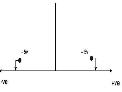
From the diagram above, we see that there is CRO which is used to detect +ve or -ve voltage. We can also detect with multimeter. The threshold voltage here is set to 5 volts. It can be any number depending on the distance between transmitter & receiver. Generally, if distance is less, voltage is set to minimum of 1 volt and similarly vice versa for more distance. If the received signal more than threshold & falls above +ve or -ve 5 volts, then it is recognized as ‗1‘. In all other cases, it is ‗0‘.
EXISTING MODEL:
It is the basic model which is used in allocating bandwidth to mobile devices. Let‘s assume genuine example of how GPS works? Every mobile user is connected to three base station depending on the frequency range of the location[11]. Same way, mobile device has 2 or more frequencies, but connected to only one. Before, when a user is trying to connect to base station, depending on the location of the users it selects three frequency range of base station which are more reasonable to collect data from base transceiver stations, it changes its station depending user‘s location in simple way in below figure(x) where the satellites are covered in hexagonal, square and circular. but for now we take hexagonal cells as two show execution of frequency range. Similar way, when there is handoff, mobile device shifts its frequency. Each
satellite is assigned with multiple frequency which is denoted as C1-C6 of base stations and M1 as the participant. Basically the frequency of the base station is shared to participants by exchanging data through bandwidth. This bandwidth is shared with different three base stations depending on participant collection.
Figure : cellular system
In mobile communication system the
communication service is provided to user. the mobiles around the world uses GSM(global system for mobile communication) is a wireless digital signaling network which is used for communicating through mobile switching signals through GSM networking signaling protocol called GSM map. the GSM is used for connecting mobile to service station. the GSM architecture partitioned into three parts :
1. Databases.
2. Switches.
3. radio system
Acronym
BSC Base Station Controller.
BTS Base Transceiver Station.
HLR Home Location Register.
MAP Mobile Application Part.
MS Mobile Station.
MSC Mobile Switching Center.
PSTN Public Switched Telephone Network.
SSP Switching Service Point.
VLR Visitor Location Register.
Figure(X):GSM ARCHITECTURE
Using GSM radio system consists of Base Station
controllers (BSC), Base Transceiver
Stations(BTS) and mobile stations (MS). Using the radio systems, the mobile station connects to base station where signal is switched using
switches by using mobile switching
centers(MSC) and based on location area. the msc
communicates with a switched service
point(SSP). in the public switched telephone Network(PSTN) using networking seven layers the PSTN communicates with GSM gateway. the location area is found using databases of user
interface by HLR, VLR and EIR.[25]
Working of call service procedure:
The call service procedure uses basic algorithm called ―First come first serve‖ (FCFS). During FCFS when a call is processed first, it looks for available bandwidth of signals where it can provide communication. If the bandwidth is good,
than communication can be processed[11].
There will be 30 to 70 bandwidth channels in average for a single tower (base station) depending on the location. One of the basic reason for call dropping is when the user is busy in one call the bandwidth allocation is already done. When this thing happens to all available
channels under cell, including borrowed
frequencies from surrounding cells, then call is directly disconnected with a message that ―All call channels are busy, please try after some time‖.
Scenarios of call dropping:
Call dropping is caused by many factors. Loss of communication may occur due to signal range. The range of signal depends on area where people connecting. In urban where huge amount of people try connecting can cause a connection delay due to heavy traffic and coming to rural regions, the channels are not available or not in range of user. In under-ground parking or mountains region, usually transmission signal strength is very low.
(A) Heavy call traffic in peak hour: heavy traffic jams are the most common problems faced in many areas, these traffic occurs due to the following reasons
(1) If the broadcast control channel
(BCCH) and Stand-alone Dedicated Control
Channel (SDCCH) of the cell have different antennas. BCCH is a point to multipoint, unidirectional channel is used in the Um interface of the GSM cellular standard and SDCCH channel is used in the GSM system and provides a reliable connection for signaling and also used for SMS (Short Message Service) messages. The SACCH (Slow Associated Control Channel) helps to support this channel.
(ii) If the power from transmitter side and receiver sensitivity of the antenna doesn‘t match.
(B) Increase of signaling load: Increasing of signaling load usually occurs in particular season or occasion, for example in the festive seasons people start making calls or try to send bulk messages for wishing each other [19], here exactly what happens in the background is when bulk information is being sent, the radio bearers will be changing or shifting signal load is increased or servers will crash resulting in call dropping.
(C) Wrong configuration in mobile network:
The operating systems may be different. We normally use the physical configuration of the network which is similar to system's topology. If new software is installed or machine is changed in middle of network, then it should be configured according to previous existing one. [21]
(D) Network congestion through bandwidth management: In this case here overfilling of link is happened which result in network congestion and poor performance of the network, and also these DPI causes call congestion as these DPI differs depending on the mobile operators.
There are some coverage problems which causes the drop rate[20].
(E)Discontinuous coverage: when the voice quality of a BTS is poor and when calls cannot
handed over to the other cells since there is no adjacent BTS in between to transfer the calls, then it will be dropped. Another reasons why call is dropped is when signals are blocked and transmission is discontinuous call may be dropped.
(F) Poor indoor coverage: when the building is having deep densities and also low indoor signal level.
(G) Cross coverage (isolated BTS): when power is in excess level the cell causes cross coverage which results in call drop [20].
(H)Insufficient coverage: In some terrain reasons, signals are blocked which don‘t allow the call to be connected this may lead to call drop, here actually BCCH TRX is blocked which causes discontinuous coverage. Complex terrain locations have most probability.
(I) Path loss (or path attenuation): this is also
similar to electromagnetic waves and it is mainly concerned in reduction in power density due to attenuation of an electromagnetic wave and this
will be propagated through free space. Here Path
loss is a one of the major component in the process of analysis and design of the link budget of a telecommunication system. Path loss normally consists of propagation losses which occur by the natural expansion of the radio wave front in free space (which usually takes the shape of an ever-increasing sphere), and also absorption
losses (which sometimes called penetration
losses), here in this process when the signal passes through media it is not transparent to
electromagnetic waves and the diffraction losses
too and here when this becomes part of the radio wave front is been obstructed by an
different opaque obstacle, and losses
In the process of wireless communications, path loss is mainly denoted by the path loss exponent, and here the path value is normally will be always in the range of 2 to 4 (where 2 will be propagation in free space, 4 is will relatively lousy environments and in the case of full specular reflection is measured from the earth surface so this is called as Flat Earth model). In some of the environments like such as buildings and stadiums and other indoor environments, the path loss exponent will reach values from the range of 4 to 6. in this process the tunnel act as, In the study of wireless communications, path loss can be represented by the path loss exponent, whose value is normally will be in range 2 to 4 (here 2 is for propagation in free space, and 4 will be for relatively lousy environments and for the case of full specular reflection. and here Path loss is mainly expressed in dBs. In its simplest form, the path loss is calculated by using the formula
L = 10\ n\ \log_{10}(d) +C
here we r going to denote L as path loss in decibels, n as path loss exponent, d will be the distance between the transmitter and the receiver, this path loss is usually measured in meters, and C will be constant which accounts for system losses., and results in a path loss exponent less than 2.
Protocol-related issues: On the other hand packet loss is due to improper congestion control and could be minimized. [7] Removing unwanted
data in turn reduces redundancy & processing time. Analyzing the defects in surroundings of base station is called Network audit and required before setup of antennas, towers, transceiver control stations.
Network congestion occurs when a link node carries lot of data which leads to delay of queuing and packet loss or blocking off the connections. [17] Networks use protocol to exhibit stable state which is also called as congestion collapse or congestive collapse, this is a situation where the packets reach the particular destination with no communication.
Major routing problem is that there should be no loop formations while sending a packet & congestion. Here we considered TCP Reno scheme for drop-reduction which is widely used in Linux- Kernel systems and in windows server 2008.TCP Reno scheme has four stages - slow start, congestion control, fast recovery and fast re-transmit. If any data packet lost, sender receives duplicate acknowledgement or timer expired error message. Then re-transmit or recovery function occurs immediately. Now while sending packet again, the size of sliding
window is reduced below congestion threshold[7].
It also backoff its re-transmission time by 500 Ms. If there are 2 delays, then 1s is time, the connection will be on hold.
Split Mode[9] (for wireless approach): In split mode if a mobile device is in moving condition and router in specific cell acts as fixed spot host transferring data. When mobile device moves into another cell, router in that specific cell takes the position of fixed spot host. Freeze TCP has high mobility support. Now we will talk about that.
Freeze Deadline Algorithm [10] (network and
types - downward & upward. Downward is moving connection from low throughput to high throughput. That is lower bandwidth to high bandwidth. The moving of signal from higher to lower bandwidth is called upward vertical handoff. This process causes packet losses when shifting between frequency ranges due to compression of signal. FDL is freeze deadline line. It is time-out value indicating when freeze occurs. It is always half less than RTT [10].
Freeze-TCP is a solution to increase throughput in these circumstances. If there is change of router or antenna in a network, then the algorithm sends a message to server that handoff had occurred and instruct it to set window size to ―0‖. According to experiments, in upward handoff, throughput is increased rapidly in first few seconds and it falls to very low levels. In downward handoff, throughput, it is constantly low in first few seconds & then increases rapidly following fluctuations.
III. METHODOLOGY
Many Solutions are available to reduce drop connection problems. They include-
1) Load Balancing
2) Separate Paths for connection 3) Using LTE (long term evolution) 4) Service priority
5) Concurrence of signals 6) Hopping frequencies &
7) Many small error corrections.[4]
RF call drop due to uplink failure: RF call drop due to uplink failure is a kind of a call drop where the link failure occurs when the network site is unable to decode a SACCH(slow associated control channel) message, In this process when the timer is reduced by 1 and if the network site decodes as SACCH correctly the timer is increased by 2 and when the timer value reaches to zero ,then transmission will be stopped and MS comes to idle state and the call will be dropped automatically then network site attempts to release radio channel and here time gets out and BSC (base station controller) sends a clear
message to MSC (mobile switch center), and finally an uplink or downlink failure will stop sending the request to SACCH which results in timeout and lead to call drop.[25]
Rf call drop due to downlink failure: In the case of downlink failure we have mobile station(MS) which has an timer out and is being allotted by an initial value like (RTL radio timeout), due to severe interference MS won‘t be able to decode the SACCH. As SACCH acts as an important system which helps in transferring the information message, When the process shows the ‗S‘ value as 1 then it fails to decode, when if the ‗S‘ value shows 2 it will decode and when the ‗S‘ becomes zero the call will be dropped automatically.
Reasons for RF Call drop
1. Unreasonable radio parameter settings. 2. Intra-network interference.
3. Inefficient Hardware 4. Weak battery power 5. Insufficient Coverage 6. Poor signal strength
Handover failure call drop: when an MS gets an handover message from receiver side, and if it fails to handover the message to the destination, the message leads to handover failure or call drop, exactly what happens here is MS fails to possess the destination call and transmits handover message, in this situation neither MS returns to the original or sender cell channel and sender failure message and MS is separated from the system. Here, the handover control timer of BSC will be timed out and requests MSC to clear discharge, and consider this special case occasion handover disappointment call drop[24].
MIMO:
reflected signals in channel robustness and throughput and also to provide return loss.
Functions of MIMO [23]: MIMO can be divided into three classes i.e. precoding, spatial multiplexing[SM] and assorted qualities coding or precoding. precoding is nothing but we call that as multi-stream beamforming, it is thought to be all spatial handling that mainly take place at the transmitter .what exactly happens here is the same signal is being transmitted from each of the transmit antennas with proper phase and pickup weighting such that the signal strength gets increased at the receiver's end .
Here we can see some advantages, they are
These help in building up or increases the
receiver signal
Helps to lessen the multipath fading effect
Results in characterized directional
pattern
These helps in multipath propagation
Spatial multiplexing requires.
Spatial multiplexing needs MIMO antenna design. In spatial multiplexing, a high rate sign is divided into multiple lower rate streams and every stream is transmitted from an alternate transmit antenna in the same frequency channel. If the signals comes to receiver antenna array with enough different spatial signatures and the receiver has exact CSI, it can isolate these stream into parallel channels. Spatial multiplexing is an effective system for expanding the
Channel limit at higher signal to noise ratios. The
maximum number of spatial streams is
constrained by the lesser quantity of antennas in transmitter or receiver side. Spatial multiplexing can be utilized without CSI at the transmitter, however can be combined with precoding if CSI is accessible. Spatial multiplexing can also be utilized for synchronous transmission for many different recipients, and this one is called as space-division various access or multi-client MIMO, in which case CSI is required at the transmitter.
Diversity coding techniques is implemented when we don't have channel knowledge at the transmitter. In this methods, we take only one single stream and this single stream is transmitted, but here signal is coded using techniques and this is called as space-time coding. In this technique the signal is emitted from each of the transmit antennas with full or near orthogonal coding. Diversity coding techniques exploits the independent fading in the multiple antenna links to enhance signal diversity.
Possible solutions for reducing the call drop:
here some possible solutions are discussed to avoid the negative effects of network, one method to avoid call drop is priority method in this methods information or packets are transmitted on priority basis, which reduces call drop and helps in successful handover [18]. Priority schemes are implemented here which helps alleviates most of the congestion effects for some services, they are
(A) Increase the number of different route for the same call: In this we use contention free opportunities which helps in reducing call drop by using the different gateways we can route the calls, when gateway a is busy call is being routed to gateway 2.
(B) Flexibility in customer service: normally a customer expects best amount of service, giving the customer the best service will never leave network.
(C) Creation of more signaling database: planning the file size before starting will help to reduce call drop. Signaling power should be analyzed as it is strength of the connection to the mobile phone with its network, so proper analysis of signal will lead to reduced call drop.
Call drop during peak hours:
Calls are being dropped as heterogeneous networks create problems where microcells, small cells interference coexist which leads for call drop. Another reason for call drop in peak hour are handover reasons which occurs due to poor radio network interference (excess uplink handovers will be there than downlink handovers) which we can call as unbalanced power budget.
IV. DISCUSSION
In Main Switching Centers (MSC) of telecom providers or data-internet service providers, the setup for detection of malfunction will be like this. They have a screen displaying all antennas one below other. All the antenna symbols will be green colors except ones with malfunction or under repair will have red color. There is another screen prototype where it shows an antenna and the areas with names where it holds coverage. So, when there is repair, authorized person will go to the site, repairs it. Most of the problems could be are solved from this prototype only unless it‘s major problem. In some countries, where there are power failures, MSC has two generators which runs on fuel. If one goes out, it has other one. Call history server rooms are separated from application server rooms and others. Each room has air conditioning fixed in walkway, back and top of servers. Temperature is set to certain cold temperatures which is varied up to 10 degrees celsius according to servers heat-up. If there is peak time
of calls, specifically at festival times,
temperatures are lower down. Uptime of servers varies from 140+ hours to months or years. No matter what cost it takes, telecom companies try to implement servers with large uptime since no personnel is needed to guard the server room for every 3 days.
TCP Reno: Queuing delay, frame or data packet loss, blocking of new connections are few things caused if congestion occurs. TCP Reno can deal
with multiple packet loss. It has fast recovery. what‘s the improvement of slow start.
Small Cells Interference:
Nowadays mobile traffic is increased triple times than before. With increased data usage, it became a burden for managing large traffic. So, macro cells are converted into small cells. The same frequency is allotted to small cells in one macro cell.[31]
Signals from two cells interfere - due to improper frequencies assignment. Signals of same frequency overlaps. Suppose there is a airport, railway station where 20 routers are present in same area. 100 devices (laptops, mobiles) are connected to it. But our laptop displays output of browsing thoroughly in between several noises. This is because receiver in our laptop is designed in a way that attracts desired frequency and then amplifies or attenuates other frequencies if received. Also, frequency allocation band oversees that different routers has slightly different frequencies such that overlap does not occur. FCC & ITU are 2 companies I know that allocates frequencies.
In the present days as it‘s a developed market where LTE is being used everywhere that has made small-cell initiation. LTE is an essential driver for small cells as it is a key for spectral efficiency. When we consider about network small cells has three main aspects.
1. Small cells help to increase the capacity of the network in with high client densities and in indoor buildings where there are more subscribers at a time. 2. It improves the coverage and makes data
available with high quality service which cannot be done by macro cells, such cells are called as ‗Black spots‖.
ALOHA is protocol that uses only one band. Transmission or reception. If collision
occurs, then re-transmit. This decreases
efficiency. So, throughput should be maintained. Here, throughput is measured in the probability of success of transmission.
Solutions:
→ Routers have the option of switching frequency if neighboring outer signal collides with the current router.
→ Guard bands are one of the solutions.
→ Femtocells are one of solutions. Femtocells are devices same as modems which can be connected to service provider‘s network through broadband or DSL cable.[32] It handles up to 8 mobile devices. Enterprise edition can handle up to 16 devices. So, more data can be pushed to Wifi licensed band instead of less bandwidth bands of cellular networks. Hence no worry of interference, building obstacles faced in general scenario, low power, handover problems
Handover Failure:
The handover occurs during initiating a call during these process when the received signal level is not reachable and it is a certain threshold value and from congestion in communication.
Every mobile device act as user equipment(UE) where this mobile device has the hardware for RF sensing and have connection manager very each mobile can connect based on radio connections or users actions. Here the system model assists the UE to decisions which may cause in handoff or handover in the connection. This handover is controlled by SDN controller, which involves the open flow entry modification protecting from UE which can cause IP address modification.[33]
A) Handover occurs when delayed:
In case of handover occurs when delayed on radio link failure before handover in user source mobile before the handover was placed, here user equipment (UE) try to re -establish the radio connection in end connection cell. This
radio link failure occurs in source mobile when a handover procedure is called upon.
(B) Handover occurs when too early:
In case of handover occurs before in cell where the radio link failure occurs in target mobile during handover procedure called upon, and UE retries to establish its radio signals in the user mobile.
(C) Handover occurs when received to wrong cell:
In case of handover to wrong mobile where the radio link failure occurs in the target cell during the handover procedure called upon, where UE tries to establish its radio link in a mobile which isn‘t the user mobile nor the end user (target) mobile. [29]
All these failure occurs are detected after an RRC (Radio Resource Control) connection is reestablished or if there is flag raised after RRC connection setup, where RRC connection reestablishment is show in message log. When this type of flag is raised, the eNODE B can ask UE to the failure of link information by UE information request message.
In case if reconnection is established in wrong cell which isn‘t the source eNODE B. which leads to bad radio link failure information to source eNODE B with bad information. This is indicated by X2-AP radio link failure indication message. This X2 _AP radio link failure gives indication message with all content which causing this failures.
Freespace & Pathloss:
Pathloss is nothing but a free space caused between the electromagnetic wave signals due to certain obstacles such as refraction, reflection, diffraction and absorption. Previously we have discussed how the path loss is calculated and what is the range of the path loss and how it is reduced due to different mediums and now we discuss how to avoid call dropping and filling the free spaces between electromagnetic radio waves.
given channel of power Pt .l let rt be the received
signal of power pr , where pr is the average over
any signal disturbances caused due to shadowing (shadowing is referred as problems faced during call process. We have many problems in shadowing, But the more important problem is faced in areas like flat terrain, heavy or moderate tree densities place and hilly terrains regions). The linear path loss is defined as the ratio of transmitted power by receiver power [35]-[36].
p
l=p
t/p
rReflection, Diffraction, scattering, Absorption:
These are basic propagation mechanisms in path loss during wireless communications. Here reflection is caused when electromagnetic waves interferes with an object and diffraction
occurs between transmitter and receiver,
whenever these two are obstructed by any one of the surface (sharp edge), this loss occurs and another loss called scattering occurs when the obstacles are very large (unit per volume) or when objects are small when compared to wavelength.
Absorption losses are mainly caused when a radio signal is not transparent to radio signal, when this signal passes through a medium.
V. CONCLUSION
1) The signal handover can be overcome by controlling traffic which is done by base station by allotting each receivers with proper radio signal link with in two mobiles.
2) With the help of the fast recovery algorithm of tcp reno the single packet loss is controlled with
one window by eliminating fast recovery
mechanism after one packet is lost.
3) Small cells interference could be avoided with management of frequencies.
4) By introducing subnet agents we can reduce handover failures, as these helps in buffering incoming packets during handoff procedure 5) Free space loss can be minimized by
introducing non diffracting waves which
produces focused beams without lenses
REFERENCES
[1] S. Kumar, S. Nanda, "High Data-Rate Packet Communications for Cellular Networks Using CDMA: Algorithms and Performance", IEEE J. Select. Areas Common, vol. 17, pp. 472-485, March 1999
[2] Ahmad Alsolaim and Janusz Starzyk, ―Dynamically Reconfigurable Solution in the Digital Baseband Processing for Future Mobile Radio Devices‖, Ohio University, Electrical and Computer Engineering Athens, OH 45701 USA
[3] OFDM Baseband Receiver Design for Wireless Communications, Tzi-DarChiueh and Pei-Yun Tsai© 2007 John Wiley & Sons (Asia) Pte Ltd. ISBN: 978-0-470-82234-0
[4] Call Dropping Problems in Mobile Networks, International Journal of Advanced Research in Computer Science and Software Engineering, © 2014, IJARCSSE, 1051Volume 4, Issue 7, July 2014, ISSN: 2277 128X
[5] Survivable Mobile Wireless Networks: Issues, Challenges and Research Directions by James P.G. Sterbenz, Rajesh Krishnan, Regina Rosales Hain, Alden W. Jackson, David Levin,
Ram Ramanathan, and John Zao BBN
Technologies 10 Moulton Street, Cambridge, MA 02138, USA
[6] INTELLIGENT WIRELESS
COMMUNICATION SYSTEM USING
COGNITIVE RADIO Asma Amraoui , Badr Benmammar, Francine Krief, Fethi Tarik
Bendimerad LTT Laboratory of
Telecommunication Tlemcen, UABT,
Algeria LaBRI Laboratory Bordeaux 1
[7] TCP in Wireless Environments:Problems and Solutions by YETIAN, KAIXU, AND NIRWAN ANSARI
[8] Alagu S,Meyyappan (2012, December). A Novel Handoff Decision Algorithm in Call Adimission Control Strategy to Utilize the Scarce
Spectrum in Wireless. Retrieved from
http://airccse.org/journal/jwmn/1212wmn08.pdf
[9] CONVERGENCE BETWEEN SIGNALS
INTELLIGENCE AND ELECTRONIC
WARFARE SUPPORT MEASURES by Zsolt
HAIG, haig.zsolt@uni‐nke.hu, National
University of Public Service, Budapest, Hungary
[10] Freeze DeadLine Algorithm for Vertical Handoff in Heterogeneous Wireless Networks, International Journal of Control and Automation Vol. 7, No. 12 (2014), pp. 247-260 by Hyeon-Jin
Jeong and Seung-Sik Choi,
http://dx.doi.org/10.14257/ijca.2014.7.12.23
[11] Gill, S., & Brent R, P. (2012). Advanced Adaptive Call Admission Control for Mobile
Cellular Networks: Cell Breathing, Load
Shedding and Bandwidth Degradation.
International Conference on Advances in
Computing, Communications and Informatics (ICACCI-2012)
[12] Effects of Interference on Wireless Mesh Networks:Pathologies and a Preliminary Solution by Yi Li, Lili Qiu, Yin Zhang, Ratul Mahajan(Microsoft Research), Zifei Zhong, Gaurav Deshpande, Eric Rozner, University of Texas, Austin
[13] Techniques for Improving the Performance of TCP in CDMA Cellular Networks by Biswajit Ghose and Vikas Jain Department of Computer Science and Engineering University of California, San Diego
[14] L. Zhengye, S. Yanming, K. W. Ross, S. S. Panwar and Y. Wang, ―LayerP2P: Using Layered Video Chunks in P2P Live Streaming‖, J. IEEE Trans. on Multimedia, vol. 11, no. 7, (2009), pp.1340-1352
[15] On the Static Resolution of Digitally Corrected Analog-to-Digital and
Digital-to-Analog Converters With Low-Precision
Components, Matthias Frey, Member, IEEE and
Hans-Andrea Loeliger, Fellow, IEEE,
TRANSACTIONS ON CIRCUITS AND
SYSTEMS—I: REGULAR PAPERS, VOL. 54, NO. 1, JANUARY 2007
[16] Raja Lakshmi, K. (2010). Solving
Assignment Problem of Cellular Mobile Network using Iterative Local Search Algorithm. The International Conference and Workshop on Emerging Trends in Technology. New York, NY: ACM.
[17] Yue Maa, James J. Han and Kishore S. Trivedi, Call Admission Control for Reducing Dropped Calls in CDMA Cellular Systems ([email protected],
[email protected], [email protected])
[18] Wireless Digital Communication by Dr. Kamilo Feher, Pearson Education, and ISBN-10: 0130986178 • ISBN-13: 9780130986177
[19] J. C. Jr. Liberti and T. S. Rappaport. Analysis results for capacity improvements in CDMA. IEEE Trans. ISBN 13 978 -0-470-01593-3 (HB)
Journal of Electronics and Communication Engineering (IOSR-JECE) ISSN : 2278-2834,
ISBN : 2278-8735, PP :
26-32www.iosrjournals.org
[26]
www.schoolphysics.co.uk/age16-19/Wave%20properties/Wave%20properties/text/ Theories_of_light/index.html
doi:10.1155/2007/17826
[21] Y. Ma, J. J. Han, Global Software Division, Motorola, Inc., Schaumburg, IL 60196, USA and K. S. Trivedi, Department of Electrical and
Computer Engineering, Duke University,
Durham, NC 27708, USA, Channel Allocation with Recovery Strategy in Wireless Networks.
[22] Wahida Nasrin, Md Majharul Islam Rajib, ―An analytical approach to enhance the capacity of GSM frequency hopping networks with
intelligent Underlay-overlay‖ Journal of
communication, Vol 4,No. 6, July 2009.
[23] Stefan Schindler, Heinz Mellein,
"Assessing a MIMO Channel" (http:// www. rohde-schwarz. com/ appnote/ 1SP18. pdf,), Rohde & Schwarz, pg. 11.
[24] H. Olofsson et al., ― Interference Diversity as Means for Increased Capacity in GSM‖, in Proceedings of 1st EPMCC, Italy, 1995, pp.97- 102
[25] Tejashri, H. (2011). A DISTRIBUTED DATABASE ARCHITECTURE FOR GLOBAL ROAMING [27] Reducing Call Drop in Mobile Cellular Communication by using MIMO Antenna by Rohit Das, Vikas, Hrishikesh Narayan Tripathi, Shri Mata Vaishno Devi University. Volume 4, Issue 1, January 2014. ISSN 2277 128X
[26]www.schoolphysics.co.uk/age16-19/Wave%20properties/Wave%20properties/text/ Theories_of_light/index.html
[27] Reducing Call Drop in Mobile Cellular Communication by using MIMO Antenna by Rohit Das, Vikas, Hrishikesh Narayan Tripathi, Shri Mata Vaishno Devi University. Volume 4, Issue 1, January 2014. ISSN 2277 128X
[28] Analysis of Different Congestion
Avoidance Algorithms by IRACST –
International Journal of Computer Networks and Wireless Communications (IJCNWC), ISSN: 2250-3501, Vol.3, No1, February 2013
[29] Http://www.lte-bullets.com/LTE in Bullets - Mobility Robustness Optimisation.pdf. (n.d.). MOBILITY ROBUSTNESS OPTIMISATION.
[30] http://electronics.stackexchange.com/questi
ons/94388/how-come-radio-signals-dont-interfere-with -each-other-all-the-time
[31] Coexistence of Wi-Fi and Heterogeneous
SmallCell Networks Sharing Unlicensed
Spectrum by Haijun Zhang, Xiaoli Chu, Weisi Guo and Siyi Wang, Cornell University, 5 May 2015https://en.wikipedia.org/wiki/Femtocell
[32] Challa, R., Raza, S., Nam, S., & Hyunseung Choo. (2016). SD-MONET: Software Defined Mobility Management in Enterprise HetNet.
[33] http://electronicdesign.com/communication
s/understanding-small-cell-wireless-backhaul
[34] Torlak, M., Prof. (n.d.). Path Loss.
Retrieved March 26, 2016, from
https://www.utdallas.edu/~torlak/courses/ee4367/ lectures/lectureradio.pdf