ISSN (Print) : 2320 – 3765 ISSN (Online): 2278 – 8875
I
nternational
J
ournal of
A
dvanced
R
esearch in
E
lectrical,
E
lectronics and
I
nstrumentation
E
ngineering
(A High Impact Factor, Monthly, Peer Reviewed Journal)
Website: www.ijareeie.com
Vol. 7, Issue 2, February 2018
Current Control Technique for DFIG Based
Wind Energy Conversion System
P.Keerthana1, D.Prasad2
M.E Scholar, Department of EEE, Sona College of Technology, Salem, Tamilnadu, India1 Assistant Professor, Department of EEE, Sona College of Technology, Salem, Tamilnadu, India2
ABSTRACT: Wind energy is one of the most promising renewable energy resources. The hysteresis control is implemented in this paper for controlling the power flow between grid and rotor side. Doubly Fed Induction Generator (DFIG) based wind turbine is growing technology and it is applicable for fixed speed generator system. The proposed method is based on a hysteresis control technique, which has more benefits then other controlling methods it reduces the current error. the proposed Hysteresis control based DFIG for WECS is simulated using MATLAB/Simulink.
KEYWORDS: Hysteresis Control, Doubly Fed Induction Generator, Wind Energy Conversion System(WECS),nonlinear load, voltage source converter.
I. INTRODUCTION
In today's scenario renewable energy places major role than the non renewable energy. However, the non renewable energy sources such as coal, oil, gas are limited in nature. Now there is a need for the future demand. The main advantages of these renewable sources are eco-friendly and unlimited in nature. The technical advancements in wind energy resources system is increased, due to this wind energy is mostly preferred.
In older days, wind turbine have been used as fixed wind turbines with squirrel cage induction generator and capacitor banks because of their simplicity and low cost. Wind turbine characteristics has to be observed for extracting maximum power from wind energy. The machine has to run at variable speed for extracting more power to improve the wind energy production. The mostly used generators invariable speed wind energy conversions are doubly fed induction generators (DFIG), and synchronous generators. In the case of induction generators, the stator is directly connected to the network and the rotor is mediated by the electronic converter, the reason why they are inserted in systems with partially rated power electronics. The possibility to control the frequency and the amplitude of the generated voltage through the rotor circuit, independent of the speed rotation, made for many years the DFIG the main choice invariable speed WECS of great size directly connected to grid as it can be seen in. Synchronous generators are completely decoupled from the grid. That is why they are considered part of the systems with full-scale power electronics.
In recent years multi pole PMSG is the preferable choice, because a gear box is not necessary, which reduces the losses on the WECS, minimizing maintenance requirements and increasing the system reliability and efficiency. A chopper circuit is commonly used in the dc-link to dissipate power in case of grid-side faults. Out of all variable speed wind turbines, Doubly Fed Induction Generators (DFIG) are mostly preferred. Because of their low cost, higher energy output, lesser converter rating and enhanced utilization of generator. DFIG also provide good damping performance for weak grid. Independent control of active and reactive power is achieved by decoupled vector control algorithm. The vector control of such system is realized in synchronously rotating reference frame oriented in either voltage axis or flux axis.
II. PROPOSED SYSTEM CONFIGURATION
ISSN (Print) : 2320 – 3765 ISSN (Online): 2278 – 8875
I
nternational
J
ournal of
A
dvanced
R
esearch in
E
lectrical,
E
lectronics and
I
nstrumentation
E
ngineering
(A High Impact Factor, Monthly, Peer Reviewed Journal)
Website: www.ijareeie.com
Vol. 7, Issue 2, February 2018
these nonlinear load harmonic current.RSC is controlled for achieving MPPT and also for making power factor at the stator side by using voltage oriented reference frame. Synchronous Reference Frame(SRF) control method extracts the fundamental component of load currents for the GSC control. The proposed system is displayed in figure 1.
Figure.1. Proposed System
In this proposed system hysteresis control is implemented to control the current. DFIG is more efficient and used in wind conversion system. The maximum power point tracking enables the system to continuously extract the maximum energy from the wind by generating an appropriate rotor speed reference. Wind turbines uses DFIG, which consists of wound rotor induction generator and an IGBT-based PWD converter. The stator winding in the generator is directly connected to 50 Hz grid. While the rotor is fed at variable frequency through the converter. It extracts maximum energy from low speeds wind using DFIG technology by optimizing the turbine speed. It also minimizes mechanical stresses on turbine during gusts of wind. It has ability for power electronic converters to generate or absorb reactive power so that installing capacitor banks will eliminated in DFIG technology. In case of squirrel cage induction generator capacitor banks has to be installed. The back to back Voltage Source Converter(VSC) is connected.
III. HYSTERESIS CONTROL STRATEGY
The figure 2 shows the current ramping up and down between two limits. The hysteresis band current control method is popularly used because of its simplicity in implementation, fast response, independent of load parameters as compared with pulse width modulation technique.
ISSN (Print) : 2320 – 3765 ISSN (Online): 2278 – 8875
I
nternational
J
ournal of
A
dvanced
R
esearch in
E
lectrical,
E
lectronics and
I
nstrumentation
E
ngineering
(A High Impact Factor, Monthly, Peer Reviewed Journal)
Website: www.ijareeie.com
Vol. 7, Issue 2, February 2018
Hysteresis current control (HCC) is used to control the power flow exchange between the grid and rotor side. Hysteresis current controller derives the switching signals of the inverter power switches that reduces the current error. The switches are prohibited asynchronously to ramp the current through the inductor up and down so that it follows the reference. When the current flow through the inductor exceeds the upper hysteresis limit, a negative voltage is passed by the inverter to the inductor. This causes the inductor current to decrease. Once the current reaches the lower hysteresis limit, a positive voltage is passed by the inverter through the inductor and this causes the current to increase and the cycle repeats. The current controllers of the three phases are designed to operate independently. The figure 3 shows the block diagram of the proposed system.
Figure.3.Proposed System Block Diagram
They determine the switching signals to the respective phase of the inverter. The hysteresis current control plays vital role in power electronics and provide continuous ac power supplies where the machine is to produce a pure sinusoidal ac output.
There are many current control techniques , among them hysteresis current control is preferred for their simplicity, quick response current loop. Additionally, it does not need any knowledge of burden parameters. The main role of this control system in current regulated inverters is to compel the current vector in the three phase load according to a reference curve.
IV. SYSTEM CONTROL
Hysteresis control is provided in both grid and rotor side of the system .In rotor side voltage and current from rotor is feed and it is compared with current reference then it is passed to hysteresis control. Then it is passed to pulses reference unit, according to this pulses the rotor converter is activated. In the gird side, hysteresis control is used to synchronizes the grid and rotor side current, voltage, phase angle and other parameters. As per the load required grid side converter is activated and connected with grid and loads. The rotor side converter provide active and reactive power control of the machine while the grid side converter keeps the voltage of the DC- link constant.
V. RESULT ANALYSIS AND DISCUSSION
ISSN (Print) : 2320 – 3765 ISSN (Online): 2278 – 8875
I
nternational
J
ournal of
A
dvanced
R
esearch in
E
lectrical,
E
lectronics and
I
nstrumentation
E
ngineering
(A High Impact Factor, Monthly, Peer Reviewed Journal)
Website: www.ijareeie.com
Vol. 7, Issue 2, February 2018
can be made in between GSC and RSC. By providing capacitor is acts as a active filter. Then dc is converted into ac and the connected to the grid. From grid, it is supplied to nonlinear loads.
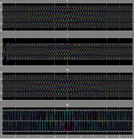
Figure. 4. Input voltage and input current waveform
The output voltage and current from DFIG with RSC and GSC converter along with DC source for converting purposes AC/DC/AC and then connected with grid and loads. The output waveform of voltage and current connected to grid were shown in figure 5.
ISSN (Print) : 2320 – 3765 ISSN (Online): 2278 – 8875
I
nternational
J
ournal of
A
dvanced
R
esearch in
E
lectrical,
E
lectronics and
I
nstrumentation
E
ngineering
(A High Impact Factor, Monthly, Peer Reviewed Journal)
Website: www.ijareeie.com
Vol. 7, Issue 2, February 2018
VI. CONCLUSION
The simulated grid side and wind turbine side parameters and their results have been displayed. Considering the results it can be said that DFIG proved to be more reliable in current and voltage parameters. This generator provides stable system output when connected to grid side with proper converter control system and hysteresis control. Hysteresis control provide more efficient and quick response and harmonic reduction when connected to non linear loads. In this proposed DFIG ,RSC provide reactive power for induction machine and load reactive power has been supplied from GSC. This proposed hysteresis control based DFIG for WECS with an integrated active filter has been simulated using MATLAB/Simulink and the results are verified with test prototype of this WECS.
REFERENCES
[1] Saeed Heshmatian, Ahad Kazemi, Mahyar Khosravi, “Fuzzy Logic Based MPPT for a Wind Energy Conversion System Using sliding mode Control”, IEEE Transaction on energy conversion, Vol 17, no.8 (2017)
[2] Abdullah Asuhaimi B. Mond Zin, Mahmoud Persaran H. A, “An overview on DFIG generators controls and contributions to wind based electrical generation”, IEEE Transaction on energy conversion, (2012)
[3] Syed Muhammad Raza Kazmi, Hiroki Goto, “A novel algorithm for fast efficient speed sensor less maximum power point tracking in wind energy conversion system”, IEEE Transaction on energy conversion, Vol 58, no.1 (2011)
[4] R. Pena, J.C. Clare, “DFIG using back to back PWM converter and its application of variable speed wind energy generation”, IEEE Transaction on energy conversation. (2008)
[5] S.S. Murthi, Bhim Singh, “A comparative study of fixed speed and variable speed wind energy system conversion system feeding the grid”, IEEE Transaction on energy conversion. (2007)
[6] Wenzhong Gao, Ziping Wu, Jianhui Wang, “A review of inverter and frequency control technologies for variable speed wind turbines”, IEEE Transactions on energy conversion. (2003)
[7] Rajib Datta and U.T Ranganathan, “Variable speed wind power generation using DFIG – A comparison with alternative schemes”, IEEE Transaction on energy conversion, Vol. 17, no. 3 (2002)
[8] Firuz Zare and Gerard Ledwich, “A hysteresis control for single phase multilevel voltage source inverter-PLD implementation”, IEEE Transaction on energy conversion, Vol 17,no.5 (2002)
[9] Edward Muljadi, “Effect of Variable Speed Wind Turbine Generator on stability of a weak grid”. IEEE Transaction on energy conversion. (2007)