Ultrasonic Sensor Based Smart Fan
Amit Baran Roy
1, Apratim Halder
2, Rahul Sharma
3UG Student, Dept. of Instrumentation Technology, BMS College of Engineering, Bangalore, India1 UGStudent, Dept. of Instrumentation Technology, BMS College of Engineering, Bangalore, India2 UG Student, Dept. of Instrumentation Technology, BMS College of Engineering, Bangalore, India3
ABSTRACT: Nowadays in the era of Intelligent Systems; a smart fan is very much essential to the concept of “Smart Homes”. Thus taking in view of the recent developments in home automation we developed a circuit which tracks the presence of person in a room. Most of the previous researches included IR and PIR sensors as the tracking sensor. Performance of Infrared sensors has traditionally been limited by their poor tolerance to light reflections such as ambient light or bright object colors. The Passive Infrared sensors have tolerance problems with temperature limit values. But ultrasonic distance sensors do not have gaps in the coverage zone like a PIR sensor and overall detection range is comparable to that of a PIR sensor. Thus in this paper we suggested the use of ultrasonic sensor module to measure the distance between the human and based on the pre-defined setpoints we have varied the speed of a small fan in the prototype . AT89s51 microcontroller and the ultrasonic transducer module HC-SR04 forms the basis of this circuit. The ultrasonic module sends a signal to the object, then picks up its echo and outputs a wave form whose time period is proportional to the distance. The microcontroller accepts this signal, performs necessary processing and varies the intensity of the fan. We also depicted a concept where these sensors can be attached to overhead ceiling fans propose use of Maximum length sequence (MLS) diffusors for sensing a 360 degree circumference beneath the fan and a thermostat to maintain the temperature in the room.
KEYWORDS: PIR, HC-SR04, MLS, Smart Fan
I. INTRODUCTION
In hot tropical countries like India where temperatures soar above 40 degrees Celsius in most regions during summer it becomes very uncomfortable to live without a fan. In fact fan plays an integral role in our households. Using a fan was the standard way of cooling down and still is for many people. Unfortunately fans do not have very efficient or useful features when it is desirable to change the direction of air flow. It requires physical effort which may be difficult if the fan is large or the user is of elderly age. In addition it may require multiple attempts before actually getting the fan to redirect air flow in the exact desired direction. Thus, we decided to initiate a system that could solve the daily stresses and inconveniences of fan use by automating the process.
II. LITERATURE SURVEY
This section presents the previous research that had been done on human detection system by using different types of sensors. This research work is based on automatic person detection system by using IR sensors [1]. But it is a known fact that IR sensor detection accuracy decreases with increasing reflection distance and change in detection is seen due to the differences in temperature conditions [2]. Another research was done on human tracking system using pyro electric infrared detectors [3]. But PIR sensors have narrower sensor field view for high temperature range with less sensitivity and specifically sensitive to thermal radiation [4]. Another research paper focussed on human tracking system by using ultrasonic distance sensor [5]. In our paper we have used a similar setup with the presence of MLS Diffusors for sensing maximum possible coordinates beneath the fan in a given room for saving power and also eliminates the disadvantage of only one person getting detected at a time.
III. METHODOLOGY
The principle of our project is based on ultrasonic sensors, also known as transceivers or transducers which work on the broader principle of radar or sonar. These technologies evaluate attributes of a target by gauging the echoes from radio or sound waves respectively. Active ultrasonic sensors generate high frequency sound waves and measures the time interval between transmission of the signal and reception of the echo. This principle helps us in acquiring the distance between the object and the transmitter module.
Figure 1: Block Diagram of the System
Figure 1 shows the basic block diagram of an ultrasonic sensor based smart fan. The first part of the block diagram depicts the object (in this case the presence of a human) and the ultrasonic sensor module HCSR04. The next part portrays the control action by the AT89S52 microcontroller with the help of predefined set-points. These set-points are generated with the help of KEIL software which is used to develop a C code and hence, the HEX code generated is uploaded on the microcontroller. This is fed to a motor driver circuit which in turn helps in the controlling of the fan.
Figure 2: HC-SR04 Ultrasonic Module
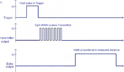
The HC-SR04 ultrasonic module has a ranging distance from 2cm to 500cm with a resolution of 0.3cm. It requires a voltage supply of 5V and a standby current of less than 2mA. The module transmits an ultrasonic signal, receives its echo and measures the time duration between the two events and generates a waveform where the high time peak is modulated by measured time and is proportional to the distance. The timing diagram is as shown:-
In this figure, a 40Khz pulse train is transmitted just after a delay of 10uS triggering pulse and the echo output is received after some time. The next pulse is triggered after the echo is faded away and this time period is known as cycle period. It should be noted that the cycle period should not be less than 50mS. There were two key considerations while selecting the sensors.
1. The effect of temperature on the range of the sensor:
The speed of sound waves (c) in air varies as a function of the temperature. If the temperature (T°C) is known, the relation can be given as:
cair = 331.5 + (0.6*T0C) m/s
Now, considering an operating range of 20°C – 35°C, the net error comes out to be 2.6%.
2. The area covered by the sensor:
Traditionally, the ultrasonic sensor is fixated a point which emits sound waves occupying a cone in the free space. This means that if the sensor is fixated a central point in the room and the occupant is in the corner, the sensor might not detect him at all (fig. 3).
In our design, we propose usage of acoustic diffusing panels based on MLS algorithm. Using panels will ensure that the sensor can detect the occupant in any part of the room.
Fig. 4: Sensing Distance diagram
III. IMPLEMENTATION
The 2 main components for this setup are
1.8051 MICROCONTROLLER( IC AT89S52) :- The AT89S52 is a low-power, high-performance CMOS 8-bit microcontroller with 4K bytes of In-System Programmable Flash memory.
2.L293D MOTOR DRIVER :- L293D is a dual H-bridge motor driver integrated circuit (IC). Motor drivers act as current amplifiers since they take a low-current control signal and provide a higher-current signal. This higher current signal is used to drive the motors.
The flowchart developed for the program is shown below:-
Figure 5 : Process Flowchart
Port pin 1.0 and 1.3 is configured as the output port for sending the digit drive patters and signals respectively. We have set port pin 3.5 as output pin for sending the trigger signal to the ultrasonic module and starting transmission whereas port pin 3.2 is set as input pin for receiving the echo.
We have set both timer 0 and timer 1 of the microcontroller as mode 1 with the gate bit of timer 0 set. The timer 1 is used for generating the 10uS delay. Here, the lower timer 1 register TL1 is loaded with initial value F6h and the higher timer 1 register TH1 is loaded with FFh so that timer 1 counts till 10 pulses after which overflow flag TF1 gets set. The trigger pin 3.5 is set high during this period after which it gets low as soon as TF1 goes high to generate the 10uS trigger pulse. The ultrasonic module issues a 40Khz pulse wave form after receiving this trigger and the program waits till a valid echo is obtained at P3.2. When a valid echo is received, the timer 0 starts counting by making TR0 pin set. It continues counting till the echo signal at P3.2 vanishes. Now, the count value of timer 0 which is stored in registers TH0 and TL0 is fed to data pointer DPTR register of 8051 (16 bit register formed by two 8-bit registers DPH and DPL). Now, range is calculated for DPTR values less than 35000 (~35uS) beyond which we assume no echo is received. The calculations for range are shown below :-
ULTRASONIC pulse travels with the speed of sound340.29 m/s = 34029 cm/s Range of target=velocity *time ⇒34029 * TIMER0/2
⇒ 17015 * TIMER0
At 12MHz TIMER0 gets incremented for1microsecond. RANGE = 17015 centimeters/seconds * TIMER0 micro seconds = 17015 cm/s*TIMER0*(10-6) seconds as (1ms=10-6 seconds) = 17015cm/s*TIMER0*(10-6) seconds
= TIMER0/58.771 centimeters
RANGE of target = TIMER0/59 centimeters
Now, if range is less than 100 centimeters, P1.0 goes high and P1.3 goes low and the fan rotates else both pin gets high and the fan stops.
After the code is run in Keil compiler; a HEX file is
Created to dump the program on the microcontroller. A screenshot is provided to show the hex file.
IV.CIRCUIT DIAGRAM
Figure 6 : Circuit Diagram Figure 7: PCB Design of the hardware implementation
The circuit diagram is developed using FRITZING software and the corresponding PCB design is also generated.
V. ACOUSTIC DIFFUSION BASED SMART FANS: A CONCEPT
Overhead ceiling fans have become very popular over in recent years. Problems have developed as to the operations of the fans. For example, traditional fans are often left on when occupants leave rooms with overhead ceiling fans. Thus, the fans can consume unnecessary power in unoccupied rooms. Another problem occurs when newly arriving occupants to new rooms and/or to darkened rooms have to search for hard to find wall toggle switches and/or overhanging chains to turn on the ceiling fans. Warm and/or stuffy rooms can be very uncomfortable to newly arriving occupants, who would have to wait for the rooms to cool down and circulate airflow. Further, turning on and off several fans in a home or building is often so inconvenient that fans are left on.
We propose integration of the ultrasonic-sensor based module in place of the traditional IR-sensors directly with the ceiling fans in order to make them smarter and energy efficient. The intensity of the fan will vary with respect to the position of the occupant in the room and this includes their automatic switching as well. Further, we propose use of Maximum length sequence (MLS) diffusors for sensing maximum possible coordinates beneath the fan in a given room.
Fig 9: Wooden MLS diffussor
Acoustic Diffusion is a technique of evenly spreading the sound waves in a given environment. A perfectly diffusive sound space is one that has certain key acoustic properties which are the same anywhere in the space. Maximum length sequence (MLS) based diffusors are widely preferred for this purpose [5]. They are made of strips of material with two different depths and its placement follows a MLS (as shown in fig 9).
MLS is nothing but a binary sequence given by: x[n]=X*(-1)a[n] They are periodic and reproduce every binary sequence (except the zero vector) that can be represented by the shift registers (i.e., for length-m registers they produce a sequence of length 2m − 1). All maximum length sequences have a common characteristic that their Fourier Transform has a white spectrum [6]. If the sequence is used as a design pattern for a wall surface with alternating wells of two different depths, incident sound is evenly scattered into all spatial directions(Fig10).
Hence, the MLS diffusers along with the ultrasonic sensors can be used to sense the location of the occupant at any point in the room and the intensity/direction of the fan can be then optimally varied reducing wastage of power.
VI. CONCLUSION
This paper proposes the usage of ultrasonic sensor based fan in home automation. Traditional usage of PIR/IR sensors were studied and their disadvantages were noted such as their poor tolerance to light reflections or infact the temperature limit issues. The ultrasonic sensor used in the setup HC SR04 module is immune to such conditions and a small setup was tested using a 8051 microcontroller and a motor driver circuit. A simple 3 position controller fan was constructed and it yielded accurate results. Furthermore we suggested that the usage of MLS diffusors for sensing maximum possible coordinates beneath the fan in a given room. Thus the intensity of the fan can be varied reducing wastage of power.
VII.ACKNOWLEDGEMENT
We take this opportunity to express our profound gratitude and deep regards to our guide Dr. Santosh R. Desai for his exemplary guidance, constant encouragement throughout the course of the project .We also take this opportunity to express a deep sense of gratitude to the Department of Electronics and Instrumentation and the faculty members for their cordial support, valuable guidance which helped us in completing this project through various stage. Lastly we thank almighty, our parents, friends for their constant encouragement without which the project would not be possible.
REFERENCES
1] R. Mishra, S. Raza, Zulquarnain, R. Arya, and P. Kumar,“Development of Automatic Person Detection System to Control Ac Fan and Room Lights,” International Journal of Innovative Research in Science, Engineering and Technology, Vol. 2, Issue. 3, ISSN:2319-8753, March 2013. [2] B. Saracoglu,“A Guide to IR/PIR Sensor Set-Up and Testing, ”Michigan State University.
[3] M. Shankar, J.B. Burchett, Q. Hao, B.D. Guenther, D.J. Brady,“Human-tracking systems using pyro electric infrared detectors, ”Optical Engineering 45(10),106401 (October 2006).
[4] B. Saracoglu,“ A Guide to IR/PIR Sensor Set-Up and Testing, ”Michigan State University.