ISSN (Print) : 2320 – 3765 ISSN (Online): 2278 – 8875
I
nternational
J
ournal of
A
dvanced
R
esearch in
E
lectrical,
E
lectronics and
I
nstrumentation
E
ngineering
(An ISO 3297: 2007 Certified Organization)
Vol. 5, Issue 5, May 2016
Binary Integer Linear Programming Method
for Optimal Placement of PMU Considering
Single Line or PMU Outage
K.K.Deepika1, Dr.J,Vijaya Kumar2, R.S.Ravi Sankar3, J.Santosh 4
Research Scholar, Dept. of EEE, K L University, Vijayawada, India1
Associate Professor, Dept. of EEE, ANITS College, Visakhapatnam, India2
Associate Professor, Dept. of EEE, Vignan’s Institute of Information Technology, Visakhapatnam, India3
UG Student, Dept. of EEE, Vignan’s Institute of Information Technology, Visakhapatnam, India4
ABSTRACT: Phasor measurement unit (PMU) is painstaking as a promising tool for prospect monitoring, protection and control of power systems. Phasor measurement units have turn out to be the measurement technique of choice for electric power system. Optimal placement ensures the complete system observability and finds the optimal locations of PMUs with the minimum cost. Binary integer linear programming based methodology is presented for optimal placement of PMU that minimizes the cost of installation and the entire system observability. Binary integer linear programming (BILP) is a special case of integer programming where variables are required to be 0 or 1.The analytical method has been coded in the MATLAB and applied to a Seven bus system, IEEE 14 bus system, IEEE 39 bus system and IEEE 57 bus system.
KEYWORDS: PMU, Binary Integer Linear Programming, optimal placement, observability.
I. INTRODUCTION
The PMU is a power system device capable of measuring voltage and current phasor in a power system. Synchronism among phasor measurements is achieved by same-time sampling of voltage and current waveforms using a common synchronizing signal from the global positioning satellite (GPS) [1]–[3]. The overall cost of the metering system will limit the number and locations of PMUs. The PMU is able to measure the voltage phasor of the installed bus and the current phasors of all the lines connecting to the bus. That is, a PMU can make the installed bus and its neighboring buses observable. There are three basic approaches to conduct network observability analysis; namely numerical, topological, and hybrid approaches. The numerical observability approach is based on the fact that a unique solution for the state vector can be estimated if the gain matrix is nonsingular or equivalently if the measurement Jacobian matrix has a full column rank and well conditioned. The topological observability approach is based on the fact that a network is fully observable if the set of measurements can form at least one measurement spanning tree of full rank [4]. The placement of a minimal set of phasor measurement units to make the system measurement model observable is the main objective of this paper. In this paper, a model is developed to find the minimum number of PMUs and their optimal locations, so as to ensure that the network is observable fully for power system state estimation. The mathematical model is developed considering different cases like with and without conventional measurements and zero injection buses and also considering the contingencies of single Line or PMU outage. The problem is formulated as a Binary Integer Linear Programming (BILP) problem. Binary integer programming is the problem of finding a binary vector x that minimizes a linear function f, subject to linear constraints:
Min f T X (1)
such that A e q ·X ≤ b e q, (2)
Where, X is binary.
ISSN (Print) : 2320 – 3765 ISSN (Online): 2278 – 8875
I
nternational
J
ournal of
A
dvanced
R
esearch in
E
lectrical,
E
lectronics and
I
nstrumentation
E
ngineering
(An ISO 3297: 2007 Certified Organization)
Vol. 5, Issue 5, May 2016
replaced by the weaker constraint 0 ≤ x ≤ 1. The algorithm searches for a binary integer feasible solution and updates
the best binary integer feasible point found so far as the search tree grows. It verifies that no better integer feasible solution is possible by solving a series of linear programming problems. Only the branch-bus model of the network is needed for reducing the number of PMUs and their optimal locations. In this paper, a simple method is presented to implement suitable constraints in power systems having zero injections and conventional measurements. The proposed OPP method while considering channel limits is based on nodal connectivity and branch selectivity matrices. This paper has been organized into five sections. Section I presented a brief about Optimal PMU placement problem along with the literature survey as the topic. Section II detailed in brief about the power system observability analysis .Optimal PMU Placement Problem and modeling has been elaborated in detail in Section III. The results of simulated studies on different test systems have been reported in Section IV. The observations from all the results obtained has been concluded in Section V. Simulations are conducted on standard IEEE 14-bus, IEEE 39-bus, IEEE 57-bus and IEEE 118-bus systems and results were found to be efficient in comparison with the recent literature published. [5 , [6]-[9] , [10] , [11].
II.POWER SYSTEM OBSERVABILITY ANALYSIS
The estimate principle of PMU optimal placement in a power system mostly is power system observability. Whatever method is used, the observability of the power system must be checked. If the system is observable with the present measurement set then placement stops, else the placement must be continued. There are two major algorithms for power network observability analysis, topology based algorithms and numerical methods. In this paper topology based algorithm is used for observability. This algorithm uses the decoupled measurement model and graph theory. In these methods, decision is based on logical operations. Thus, they require only information about network connectivity, measurement types and their locations, if a full rank spanning tree can be constructed with the current measurement set; the system will be observable.
Rules for PMU placement:
Rule 1: Assign one voltage measurement to a bus where a PMU is placed including one current measurement to each branch connected to the bus itself.
Rule 2: Assign one voltage pseudo-measurement to each node reached by another equipped with PMU.
Rule 3: Assign one current pseudo-measurement to each branch connecting two buses where voltages are known this allows interconnecting observed zones.
Rule 4: Assign one current pseudo-measurement to each branch where current can be indirectly calculated by the Kirchhoff current law (KCL).
This rule applies when the current balance at a node is known. If all are known but one, then the current phasor of the unknown branch can be calculated using KCL.
Single Line/PMU Outage
In day to day world, fault occurrence in power system is very common. Hence the PMU can become faulty in a bus system. To overcome this problem we should consider the PMU outage case. The observability for each bus in this case would increase from one to two. This practically means that in case of losing any single PMU or single line from the system, the whole power network will remain observable. However, as PMUs are highly reliable devices, the occurrence probability of both contingencies at the same time is practically near zero and then has not been considered in this method. This will enhance the system reliability.
III. FORMULATION OF PMU PLACEMENT PROBLEM
A PMU placed at a bus not only gives the voltage phasor of that bus but also the current phasors of all incident branches to that bus. This makes the buses connected to the PMU bus observable. The main objective of the PMU placement problem is to make the system observable by putting the minimum number of PMUs into the system. The PMU placement functions can be given as follows:
Min Σ Xi where i = 1 to n (3)
ISSN (Print) : 2320 – 3765 ISSN (Online): 2278 – 8875
I
nternational
J
ournal of
A
dvanced
R
esearch in
E
lectrical,
E
lectronics and
I
nstrumentation
E
ngineering
(An ISO 3297: 2007 Certified Organization)
Vol. 5, Issue 5, May 2016
X=[ x1 x2 ……….xn]
xi is the PMU placement variable
b is the vector of length n(no. of nodes)
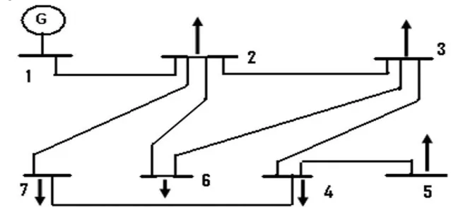
Figure 1: Line diagram of test bus system
The connectivity matrix can also be directly obtained from the bus admittance matrix by transforming it into binary form. For the 7 bus system given in figure 1, the connectivity matrix is given as follow:
Algorithm for finding the minimum number of PMUs:
1. Select the OPP Problem case like without or with conventional and zero injection buses or without and with channel limits or under normal conditions and contingency conditions.
2. Read network branch/bus data.
3. Form network connectivity matrix A and cost coefficient vector f.
4. OPP without conventional measurements under normal conditions the right hand side observability matrix b is a (N x 1) order matrix with each element equal to 1.
5. By using A, b and f matrices, solve OPP using Binary Integer Linear Programming method. 6. The variable xi is assigned to one if PMU is installed at bus I, otherwise assign zero.
7. End
Objective function: Min x1+x2+x3+x4+x5+x6+x7 (6)
Subject to constraints
x1+x 2 >=1 (7)
x1+x2+x3+x6+x7 >=1 (8)
x2+x3+x4+x6 >=1 (9)
x3+x4+x5+x7 >=1 (10)
ISSN (Print) : 2320 – 3765 ISSN (Online): 2278 – 8875
I
nternational
J
ournal of
A
dvanced
R
esearch in
E
lectrical,
E
lectronics and
I
nstrumentation
E
ngineering
(An ISO 3297: 2007 Certified Organization)
Vol. 5, Issue 5, May 2016
x2+x3+x6 >=1 (12)
x2+x4+x7 >=1 (13)
IV.LOSS OF SINGLE PMU ORTRANSMISSION LINE
The method presented in this paper aims to sustain complete observability of the entire system, even in case of single PMU or single branch outage from the system. This algorithm is based on local redundancy (LR) method, which provides a local redundancy for each bus. If you set each entry of vector b of (4) to the value of 1, it will guarantee that each bus will be observable via at least one PMU. If all entries of vector b are changed to 2, it practically means that each bus will be observable via at least 2 PMUs, directly or via incident buses to that particular bus. In other words, phasor voltage of each bus will be reached by at least two PMUs [12]. According to this issue, in case of possible single PMU loss, the power network observability will be maintained. In addition, since each bus will be observable at least via 2 PMUs from two different branches incident to that bus, in the case of loosing of one of those two lines, that bus will remain observable via another line.
Objective function: Min x1+x2+x3+x4+x5+x6+x7 (14)
Subject to constraints :
x1+x 2 >=2 (15)
x1+x2+x3+x6+x7 >=2 (16)
x2+x3+x4+x6 >=2 (17)
x3+x4+x5+x7 >=2 (19)
x4+x5 >=2 (20)
x2+x3+x6 >=2 (21)
x2+x4+x7 >=2 (22)
V. SIMULATION RESULTS
Consider 7 bus system the objective function of optimal placement can be formulated as equation (6). Observability constraints can be formulated using line data of bus system equations are (7)-(13). Solving the ILP problem (6), (7)-(13) we required two PMUs to placed in the system Identified buses are 1,7.
The objective function in (14) represents the minimum number of PMUs required for optimal system observability of buses with a single transmission line/ PMU failure. General observability constraints (15)-(22) provides solution to the problem for optimal system observability. Solving the ILP problem (14), (15)-(22) we required three PMUs to be placed in the system and their locations are at buses1,2,7. Therefore, thus the number of PMUs to be installed is increased by one.
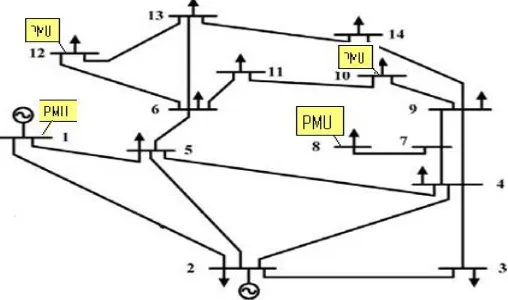
Solving the ILP problem (6), (7)-(13) for IEEE 14 bus sytem, we require four PMUs to placed in the system Identified buses are 1,8,10,12. This is shown in Fig. 2. With single line outage, the number is increased to 7 and the PMU locations are 2,3,8,10,11,12,14.
ISSN (Print) : 2320 – 3765 ISSN (Online): 2278 – 8875
I
nternational
J
ournal of
A
dvanced
R
esearch in
E
lectrical,
E
lectronics and
I
nstrumentation
E
ngineering
(An ISO 3297: 2007 Certified Organization)
Vol. 5, Issue 5, May 2016
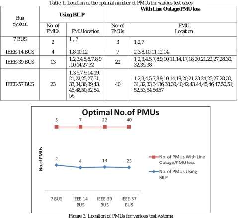
Table 1 brings out the simulation result of IEEE 14 bus system, IEEE 39 bus system and IEEE 57 bus system for optimal placement of PMU using BILP method.
Table-1. Location of the optimal number of PMUs for various test cases
Bus System
Using BILP
With Line Outage/PMU loss
No. of
PMUs PMU location
No. of PMUs
PMU Location
7 BUS
2 1 , 7 3 1,2,7
IEEE-14 BUS 4 1,8,10,12 7 2,3,8,10,11,12,14
IEEE-39 BUS 13 1,2,3,4,5,6,7,8,9
,10,14,27,32 22
1,2,3,4,5,7,8,9,10,11,14,17,18,20,21,22,27,28,30, 32,35,38
IEEE-57 BUS 23
1,3,5,7,9,14,19, 21,23,25,27,31, 33,34,36,39,43, 45,48,50,52,54, 56
40
1,2,3,4,5,7,8,9,10,14,19,20,21,23,24,25,27,28,30, 31,32,33,34,36,38,39,40,42,43,44,45,46,47,50,51, 52,53,54,56,57
Figure 3: Location of PMUs for various test systems
The requirement of number of PMUs for a bus system is stated above and it’s placement also. For a 7-bus system number of PMUs required are 2 and which are placed at bus 1and bus 7. For the same system, requirement of PMUs increases by one, considering single line outage. But this ensures reliability of the system.
VI.CONCLUSION
ISSN (Print) : 2320 – 3765 ISSN (Online): 2278 – 8875
I
nternational
J
ournal of
A
dvanced
R
esearch in
E
lectrical,
E
lectronics and
I
nstrumentation
E
ngineering
(An ISO 3297: 2007 Certified Organization)
Vol. 5, Issue 5, May 2016
number of PMUs is equal or less compared to recent reported methods. The results obtained reveal that the proposed method can be used as effective method for Optimal PMU Placement of practical network.
REFERENCES
[1] R. F. Nuqui and A. G. Phadke, “Phasor measurement unit placement techniques for complete and incomplete observability,” IEEE Trans. Power Del., vol. 20, no. 4, pp. 2381– 2388, Oct. 2005.
[2] A. G. Phadke, “Synchronized phasor measurements in power systems,” IEEE Comput. Appl. Power, vol. 6, no. 2, pp. 10–15, Apr. 1993. [3] A.G.Phadke, J. S. Thorp, and K. J. Karimi, “State estimation with phasor measurements,”IEEE Trans. Power Syst., vol. 1, no. 1, pp. 233–241, Feb. 1986
[4] T. L. Baldwin, L. Mili, M. B. Boisen, and R. Adapa, “Power system observability with minimal phasor measurement placement,”IEEE Trans. Power Syst., vol. 8, no. 2, pp. 701–715, May 1993.
[5] K.S. Cho, J.R. Shin, S.H. Hyun, Optimal placement of phasor measurement units with GPS receiver, in: Proc. IEEE Power Engineering Society Winter Meeting,vol. 1, January– February, 2001, pp. 258–262.
[6] F.J. Marın, F. Garcıa-Lagos, G. Joya, F. Sandoval, Genetic algorithms for optimal placement of phasor measurement
units in electric networks, Electron. Lett. 39(September (19)) (2003) 1403–1405.
[7] Mahdi Hajian, Ali Mohammad Ranjbar, Turaj Amraee, Babak Mozafari, Optimal placement of PMUs to maintain network observability using a modified BPSO algorithm, Electron. Power Syst. Res. 33 (2011) 28–34.
[8] F.Aminifar,A.Khodaei,M.FotuhiFiruzabad,M.Shahidehpour,Conti ngency constrained PMU placement in power networks, IEEE Trans. PowerSyst. 25(February (1)) (2010) 516–522.
[9] D. Dua, S. Dambhare, R.K. Gajbhiye, S.A. Soman, Optimal multistage scheduling of PMU placement: an ILP approach, IEEE Trans. Power Deliv. 23 (October (4))(2008) 1812– 1820.
[10] T.L. Baldwin, L. Mili, M.B. Boisen Jr., R. Adapa, Power system observability with minimal phasor measurement placement, IEEE Trans. Power Syst. 8 (May (2)(1993) 707– 715.
[11] F. Aminifar, C. Lucas, A. Khodaei, M. Fotuhi, Firuzabad, Optimal placement of phasor measurement units using immunity genetic algorithm, IEEE Trans.Power Deliv. 24 (July (3)) (2009) 1014–1020.